FIRE RISK MANAGEMENT PROCEDURE
FOR VEHICLES AND MOBILE MACHINES
SP Method 5289 June 2019 Version 2.0
FIRE RISK MANAGEMENT PROCEDURE
FOR VEHICLES AND MOBILE MACHINES
Copyright
This method is copyrighted by RISE. Neither a printed nor electronic copy of the method should be altered in any way. All RISE’s methods and all copyrights, ownerships and rights regarding those methods shall remain the sole and exclusive property of RISE.
Abstract
Risk Management of Fire Hazards
The method described in this document introduces a procedure for management of fire hazards in vehicles and mobile machines. The method particularly provides elaborate support for identification of fire hazards in newly assembled vehicles and mobile machines as well as fire hazards resulting from operation, maintenance and retrofitting. The method presents how the identified hazards can be translated to estimations of fire risks and how these can be evaluated. Recommendations are also given on fire risk reduction measures for common designs, procedures and systems. This method is based on experience and knowledge gained through research, fire investigations and other industry professional services, as well as information provided by the industry. The method does not guarantee elimination of fires but regularly performed fire risk management will promote fire safety. Key words: vehicle fires, mobile machine fires, vehicle fire hazards, mobile machine fire hazards, risk management
RISE Research Institutes of Sweden AB SP Method 5289 June 2019
Contents
Abstract ... 1 Contents ... 2 1 Scope ... 3 1.1 Field of Application ... 3 2 References ... 43 Fire Risk Management ... 5
3.1 Hazard Identification ... 5
3.2 Risk Estimation ... 7
3.3 Risk Evaluation ...8
3.4 Risk Reduction ... 9
4 Identification of Fire Hazards ... 10
4.1 Electrical Systems ... 10
4.2 Hydraulic, pneumatic, lubrication and fuel systems ... 15
4.3 Exhaust system ... 18
4.4 Brakes and tyres ... 19
4.5 Other ... 21
5 General Measures and Recommendations ... 23
5.1 Manufacturers ... 23
5.2 Operators ... 27
5.3 Workshops ... 29
6 Report ... 31 Appendix A – Typical Fire Causes
1
Scope
When a SPCR certification rule addresses to this method the colour code below shall be followed.
Text marked with red border shall be treated as requirements when applicable. Text marked with orange border shall be treated as guidelines when applicable. Text marked with yellow border shall be treated as informative notes.
1.1
Field of Application
The method is applicable to wheel driven vehicles and machines with an internal combustion or electric engine, including but not limited to buses, coaches, trucks, cars, construction equipment, mining machines and forestry machines. However, most parts of the method are sufficiently general to be applicable to all types of vehicles, also non-wheel vehicles and machines.
The method distinguishes between new vehicles/ machines and vehicles/ machines in use. New vehicles/ machines are those which have not yet been used for a specific application and who may be under production or delivery. Fire risk management will then focus on design and production issues. Vehicles/ machines in use are those which have been used in an application for some time. The scope of fire risk management is then broader. Specifically, in addition to vehicle/ machine design risks, including possible retrofitting and fire preventive measures, the risk management focusses on maintenance and repair, wear and tear, as well as known problems associated with the specific vehicle model.
2
References
AS 5062-2016, Fire protection for mobile and transportable equipment Bus Industry Confederation Inc., Fire Mitigation Advisory, Australia, 2014
P. Hart, Why Heavy Vehicles Catch Fire, Hartwood Consulting Pty Ltd, 2011 (Revised 2015)
Energy Institute, Petroleum road tanker design and construction, 3rd edition, GB,
2010
NHVR, National Heavy Vehicle regulator, National Heavy Vehicle Inspection Manual, version 2.1, Australia, 2016
Volpe National Transportation Systems Center, Motorcoach Fire Safety Analysis, US, 2009
NFPA 551, Guide for the Evaluation of Fire Risk Assessments, 2013
ISO 14121-2:2012, Safety of machinery – Risk assessment – Part 2: Practical guidance and examples of methods
IEC 60812:2006, Analysis techniques for system reliability – Procedure for failure mode and effects analysis (FMEA)
MIL-STD-882E, Standard Practice – System Safety, Department of Defense, USA, 2012
3
Fire Risk Management
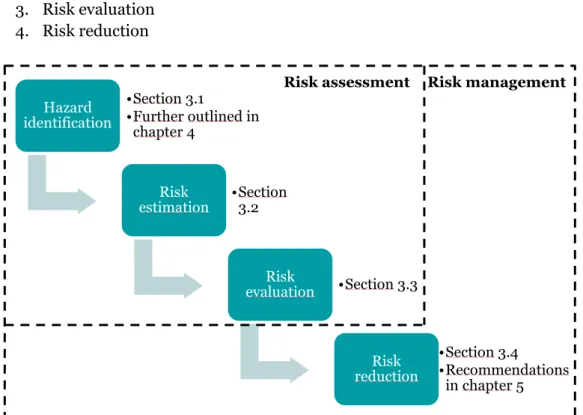
This chapter introduces a process for management of fire risks. Following the identification of fire hazards, which is further outlined in chapter 4, it is important that the remaining steps of the fire risk management process are carried out as seen in Figure 1.
A fire risk management process includes the following steps, which are explained further in sections 3.1-3.4: 1. Hazard identification 2. Risk estimation 3. Risk evaluation 4. Risk reduction
3.1
Hazard Identification
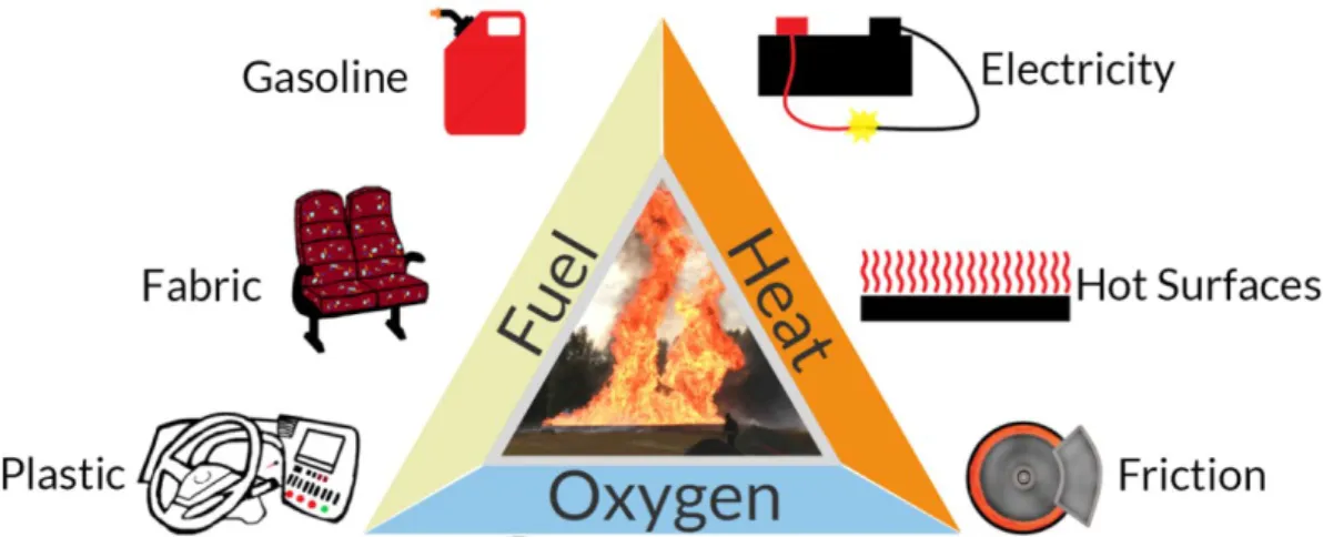
A fire hazard exists where there is a possible interaction between fuel, ignition sources and oxygen. The hazard identification process aims to answer where this could happen, when it could happen, how it could happen and why it can happen. Chapter 4 further elaborates the hazard identification procedure and provides checklists to be used as support. This is the most important step of fire risk management since the identified hazards form foundation for the whole process; unidentified hazards will inherently not be considered. The objective is to produce a list of possible fire hazards in terms of where, when, how and why it can happen.
Hazard identification •Section 3.1 •Further outlined in chapter 4 Risk estimation •Section3.2 Risk evaluation •Section 3.3 Risk reduction •Section 3.4 •Recommendations in chapter 5 Risk assessment Risk management
Identified fire hazards on vehicles/ machines in use generally include hazards related to wear and tear. This information is important, not only for the operators, but also for the manufacturers who can improve fire safety of the vehicle by correct material and component selection. Operators should ensure that relevant information is transferred back to the manufacturers and it is recommended that manufacturers ensure that regular risk assessments are performed by operators and authorized service centres on behalf of the manufacturer. It is just as important to follow a systematic procedure, such as that outlined in chapter 4, as it is to implement knowledge from previous fire incidents for that specific model. In this process it is important to determine the actual cause of the event, if possible. Often only consequences are sought, and affected parts are repaired with no consideration to the underlying causes. To determine a fire cause can be a complex work since there are often several indirect or underlying causes beyond the primary cause. For instance, a primary cause of fire could be a hot surface of the exhaust system igniting some fuel leakage. An underlying cause could then be abrasion of a fuel hose due to a loose attachment, which in turn could possibly have been caused due to shortcomings in quality routines at a workshop, in production line or at the operator. In Appendix A is given a schematic overview of typical fire causes in vehicles based on statistics from fire investigations and knowledge from experts in the field. It is recommended to review Appendix A before continuing to identify vehicle fire hazards according to this method. An understanding of what fire causes that are the most common will facilitate the identification of fire hazards. The overview in Appendix A focuses on the primary heat sources that may cause a fire. Electrical energy is generated within batteries or due to resistance heat, sparks or electric arcs and mechanical energy is due to friction or mechanical forces. Chemical energy is in this categorization including heat generated from gases and liquids, such as heat generated from the exhaust system or overheated components due to failure in the cooling system. This division is one of several different ways to organize fire causes. In addition to energy there must also be oxygen and fuel present to cause a fire, in accordance with the fire triangle, see Figure 2. In Appendix A the primary energy sources are supplemented with underlying causes in a hierarchic structure. Underlying causes marked red are at the lowest hierarchical level in this structure and are generally the events that should be prevented to avoid fire.
Figure 2. The fire triangle. All three components must be present in order to complete it and start a fire.
3.2
Risk Estimation
Following the hazard identification, risks shall be quantified by a risk estimation method. There are several different methods that could be used, and most of them are based on estimations of the likelihood and consequence of the identified hazardous events. The objective is to quantify the risks such that they can be sorted with respect to priority and actions needed.
A method often used in the vehicle industry is Failure Mode and Effects Analysis (FMEA). This method can also be applied for quantification of the vehicle fire risks. The identified hazards (failure modes) are given risk priority numbers based on quantifications of probability of occurrence, severity, and probability of detection failure. Each of the quantifications is made on a relative scale where a higher rating contributes to a higher estimated risk priority number.
Fire severity can be quantified by estimating the potential consequences for the vehicle, the driver and any passengers, as well as to the surrounding environment. The location and type of fire affect the evacuation time and the possibility to extinguish the fire. Furthermore, the consequences of a vehicle fire are affected by its operating environment, such as a city, tunnel, underground mine, sawmill, etc. Estimation of severity level should include possible number of fatalities and injuries, value of vehicle and surrounding property, time and cost of possible production stop and extent of environmental damage.
The severity level could be classified as (relating to Figure 3). Table 1 Classifying the severity level: an example.
Severity level Consequence
Catastrophic Serious damage to vehicle and surroundings. Possible fatalities.
Critical Serious damage to vehicle. Possible injuries.
Marginal Damage limited to specific vehicle section. No threat to life. Negligible Detected before fire originate (e.g. component heat rise).
Damage limited to single component or area.
During the fire hazard identification procedure, it is important to complement the inspection of a vehicle with identification of faults and shortages in the fire safety systems, status of partitions between compartments and improper design of evacuation routes, which have a high impact on the possible severity level of a specific fire hazard. Examples include faults in detection and suppression systems and, for example on a bus, missing emergency hammers and unsealed floor hatches between passenger and engine compartment. Such possible issues should be treated at design and installation level as well as in operator routines, service intervals and quality of inspections. Additional design issues for buses may include a single passenger exit adjacent to the engine compartment (high risk area, no other exits) or emergency exit/wheelchair lift above the wheel well (high risk area).
The probability of occurrence can be estimated based on fire statistics, but also with consideration to operational conditions for the specific vehicle. Operational conditions include, but are not limited to:
• Maintenance practices • Operating environment
• Operator experience and human errors • Wear and tear and life cycle of components
Statistics on vehicle fire causes (primarily for road vehicles) are presented in Appendix B and can be used to assist quantifications of probability of occurrence. Finally, the probability of detection failure can be estimated with consideration to the means for detection available. For fire risk estimation with use of FMEA, detection do not in this case include fire detection but only detection of the hazard that might result in a fire. Means for detection can e.g. include maintenance and inspection routines, driver routines and training, tyre pressure monitoring system, brake system high temperature warning, etc. It should be noted that the rating should only be lowered if an early detection would prevent the start of a fire.
3.3
Risk Evaluation
When the fire risks are quantified as described above, they shall be sorted to provide an overview of the risk image. The risk evaluation aims to provide this overview and to separate the risks which need to be addressed from risks that are acceptable.
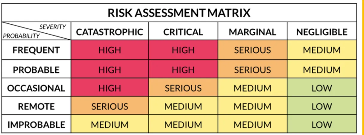
The matrix in Figure 3 below could be used for guidance.
Figure 3. Fire risk assessment matrix.
Actions corresponding to the different risk ratings could be:
• High/Serious – Immediate action required, starting with the design • Medium – Attention required to make fire risk as low as practicable • Low – No action required; risks managed by routine procedures PROBABILITY
3.4
Risk Reduction
Following the risk evaluation process, decision makers shall lay out an action plan for each identified fire risk. If a risk is considered acceptable, this needs to be carefully motivated. In general, risks need to be addressed by risk reduction measures.
Risk reduction measures can be arranged in a hierarchic structure where measures at each level should be considered.
1. Risk elimination or minimization by design 2. Passive and active fire protection systems 3. Improved maintenance and cleaning procedures 4. Improved training and quality procedures
Proposed risk reduction measures must also be assessed such that no other unacceptable risks are introduced. For instance, changes of current installations or the presence of new installations, such as a fire safety system, may introduce risks of chafing hoses/cables or hinder vision or access to vital parts. Changes to systems may also affect performance and overall safety.
Throughout the fire hazard identification procedure in chapter 4, risk reduction measures for typical fire risks are proposed. In chapter 5, general fire safety measures are presented which should be considered irrespective of identified fire hazards.
4
Identification of Fire Hazards
This chapter will guide the fire risk inspector in the identification process. It shall be used as a tool for this purpose. Note however that it cannot ensure that all possible fire hazards are identified. Apart from these guidelines, there are many factors which determine the effectiveness of a risk assessment. This could relate to the experience and competence of the inspector as well as the quality of the analysis. It could also be related to the vehicle/ machine itself. For example, potential failure components could be hidden behind structural parts and failure could be related to material properties or be caused by internal (invisible) problems.The person/company responsible for the vehicle/ machine should provide the necessary equipment to persons who are responsible for undertaking the risk assessment. Tools such as a thermal imaging camera and endoscope improve the quality of the assessment, further increasing the chance that thermal events or fire incidents are prevented.
The chapter is divided into sections covering different systems that may cause or contribute to a fire. To facilitate a good structure, it is recommended that all systems in a specific hazard area, i.e. enclosure or defined space, are covered before proceeding to the next area. Identified fire hazards shall be associated with a specific hazard area or a feedthrough between two areas.
Checklists provided must be reviewed periodically to implement experience and knowledge from past inspections to facilitate their continual improvement. Items in the checklists that are irrelevant for a specific vehicle/ machine should be removed.
Aspects relating to new vehicles/ machines should also be considered for vehicles/ machines in use.
4.1
Electrical Systems
Electrical failure is one of the most common contributors to fires and should be carefully inspected. The primary focus of this chapter are electrical systems below 60V. These are conventional systems which may be found in all vehicles/ machines (historically lead-acid batteries 12V, 24V or 48V). High voltage electrical systems (normally 300-600V), such e.g. electrical traction systems, follows the same procedure. Note however that inspecting high-voltage systems requires certified competence.
Use the checklist below and follow the recommendations for visual inspection and for measurements.
4.1.1
Checklist
The checklist shall be used to ensure that the listed items are included in the visual inspection. The succeeding inspection guideline includes considerations with respect to fire safety for the listed items.
Connections and cables to alternator Connections and cables to starter Alternator mounting
Battery mounting
Battery terminals and cables Battery equalizer
Clamps and cable ties Exposed cables Fuses
Cable feedthroughs
Cable connections and junctions Lights
Charging interface
4.1.2
Visual inspection
Start the visual inspection by looking at high current lines without preceding fuses. These pose the highest risk. Afterwards, move on to other cabling.
New vehicles/ machines
Conductors without preceding fuses are of most concern, since fuses generally work as fire safeguards. Ensure that high current lines between battery, starter and generator and other conductors without preceding fuses, e.g. from battery to fuse box, are securely mounted away from sharp edges and hot surfaces. It is recommended that these lines have an extra layer of mechanical protection, e.g. a cable tube. Note that ridged tubes may chafe on the cable inside if not mounted carefully. It is not recommended to have such tubes tied up together. It is also recommended that 30+ and 31- (+ and - wiring from the battery) are physically separated and not included in the same wiring loom.
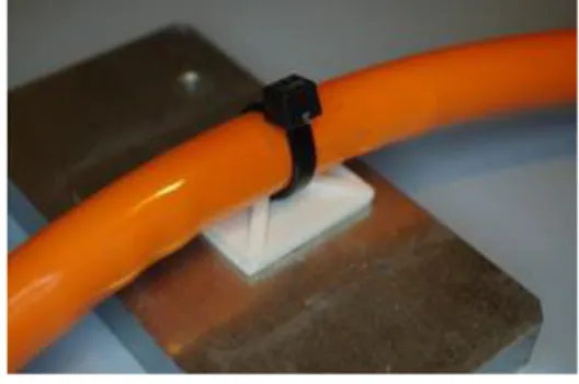
It is important that cables are mounted in ways that minimize risk for wear and chafing. Metal P-clamps (Figure 4) are bolted to grounded metal and could be considered as a short circuit risk construction. It is also recommended not to use stick-on holders (Figure 5), since there is a high risk for loosening. Alternatives are, for example, pipe holders (Figure 6) or other non-metal clamps, however, it is important that polymers used are highly resistant to thermal degradation and corrosion. It is an occurring risk that common cable ties are not resistant enough, why these should be evaluated. Cable ties used in engine compartments should at least have a rating of 150 °C.
Figure 4. Metal P-clamp - Not recommended.
Check that cables are connected properly with no loose or exposed wiring. Battery terminals should be covered to prevent unintentional short circuit. Also the positive terminal of the starter should be covered. Terminals and connections that may be exposed for corrosive substances are recommended to be protected by suitable grease, however, it occurs that specification of some materials prohibit the use of grease. Moreover, inspect that battery, alternator, starter and equalizer are mounted solid and secure. If the battery cradle or container has a pull-out or swing-out mechanism, ensure all cables are secure and have enough freedom of movement.
After inspection of conductors without preceding fuses, all other cabling should be checked. Focus on sharp edges, hot surfaces, solid mounting, connections and feedthroughs. Cable feedthroughs shall be constructed to avoid chafing and allow normal thermal development in the cable. It is also important that feedthroughs and mounting clamps are applied with correct pressure against the cable to avoid cold flow, which could result in fault currents. Cold flow may also arise if cabling has too small bending radius and a rule of thumb is to use a bending radius greater than ten times the cable diameter. Furthermore, aluminium instead of copper as conductor material may also lead to cold flow.
Look for wirings in contact with fuel, hydraulic and pneumatic hoses. Such hoses are moving because of flow or pressure changes and may cause abrasion at contact. Abrasion of the electrical cable may cause resistance heat development and electrical arcs, which in combination with the nearby fuel could result in a fast-developing fire.
Figure 6. Pipe holder – OK Figure 5. Stick-on plastic hold
Ensure that dashboard wiring and associated mountings have a high temperature rating. Temperatures under the dashboard can be equated with temperatures in the engine compartment in sunny days.
Finally inspect charging interface and charging current routes, such that no poorly dimensioned components have been added. Operators should ensure that charging is conducted without unspecified extension cables and that cables are fused.
Vehicles/ machines in use (in addition)
Identify connector surfaces with oxides, which can generate enough resistance heat to cause a fire. A high-risk example is shown in Figure 7. Also look for loose or damaged contacts.
Figure 7. Oxides in terminal block.
Examine cable insulations for signs of chafing and hardening due to thermal and chemical impact. Start with conductors without preceding fuses and continue with other exposed cables.
Look for extensions of the electrical systems. Any changes or extensions should be securely mounted and be in order. Added loads to the electrical system, e.g. a ticket machine, surveillance cameras, loudspeakers or a coffee machine, should be ensured to not cause over currents in feeding circuits. Fuses are used to ensure that, but it is a common problem that fuses are switched. Switched fuses could also be due to limitations in fuse supply or human error. This is a rather common fire hazard, and all fuses must therefore be checked for correct current rating during the fire hazard identification process.
Finally inspect lights. Lights not using LED produce a lot of heat, however, some LED lights may overheat in case of failures, e.g. incorrect voltage use or due to corrosion. Look for signs of thermal impact, such as hardenings or burn marks, on nearby combustibles, wirings and connections. Furthermore, ensure that lights have correct effect rating in comparison to the lamp base and look for connector oxides in sidelights which are exposed to road splashes. Any malfunctions of lights
or other electric accessories in driver and passenger compartments shall be examined as well.
4.1.3
Measurements
Measurements are a useful complement to the visual inspection. Highly recommended is to use a thermal imaging camera, which can identify potential fire hazards concealed from a traditional visual inspection. Run the vehicle some time before the measurement and turn on maximal load for the electrical system, i.e. all lights, stereo, etc., to stress the circuits and electrical components. Then view all wirings, terminal blocks, connections, batteries, generators, starter, LED lights and other components with the thermal camera. High current lines and wiring without preceding fuses is of most interest. Overheating of any part is easily detected by the camera, and a few degrees off compared to surrounding parts are enough to be considered as a potential risk. For instance, Figure 8 shows the positive terminal of a car battery which is about ten degrees warmer than the surrounding, indicating a poor connection. Some components, such as the generator, will produce some heat by itself, but if there are e.g. several generators the thermal camera can reveal irregular loads between generators. Take into account that copper is a good heat conductor and will transport heat from the critical point to other areas.
The overheating of any part could be due to oxidation or loose contacts. However, it may also be due to inadequate dimension of cables, connectors, fuses or PCBs. To complement the thermal scanning, it could be beneficial to also measure currents and voltages in the specific risk area and then calculate the power loss in terms of heat. Just 20 W could be enough to start a fire. However, to estimate the risk the best thing to do is to compare with measurements on similar systems. When currents are measured, both idle and load the vehicle to get an interval of the normal currents passing through the critical point.
The thermal imaging camera can also be used to inspect charging circuits. Connect the vehicle and look for any overheating, including the line between the vehicle and the charging unit.
In addition, resistance between engine block and battery can be measured to reveal a poor ground of the engine block. A large difference in potential between engine block and battery may cause the high starting currents to take uncontrollable routes resulting in a high risk. The maximum starting current could be measured to calculate the short-term power loss at the starting moment in critical routes.
Figure 8. Thermal image of the positive terminal of a car battery. Marker displays degrees Celsius. The image indicates this might be a poor connection.
4.2
Hydraulic, pneumatic, lubrication and
fuel systems
Combustible liquids are a common contributor to vehicle fires and pressurized lines and components can result in a fast-developing fire in case of leakage. Use the checklist below and follow the recommendations for visual inspection.
4.2.1
Checklist
The checklist shall be used to ensure that the listed items are included in the visual inspection. The succeeding inspection guideline includes considerations with respect to fire safety for the listed items.
Hoses delivering fluids around the engine
Oil and fluid lines near the turbo charger and exhaust system Auxiliary heaters
Hoses and pipes underneath the vehicle Clamps and connections
Fuel tank(s) and filler cap Coolant and oil levels A/C compressor and fans
Compressor of air pressure systems Hydraulic pumps
4.2.2
Visual inspection
New vehicles/ machines
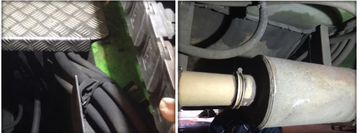
Hoses and pipes are present from the front end to the back of any vehicle why a systematic approach is important. Check different hydraulic, pneumatic, lubrication and fuel systems in turn and start with the engine compartment followed by underbody and any other areas or compartments. Ensure that all hoses and pipes are securely mounted away from hot surfaces and that they cannot rub or chafe on any sharp edges. Look for hoses in contact with each other, especially hoses of different sizes. Due to flow and pressure changes these hoses may rub on each other. Two examples of poorly mounted hoses are seen in Figure 9.
It is highly recommended to use endoscopes with lighting feature and recording feature to inspect on a larger screen. The inspector can easily miss rubbing and chafing parts without an endoscope due to crowded areas cluttered with components and other obstructions.
Figure 9. Example of poorly mounted hoses. Left: hoses of different sizes in contact with each other and in contact with metal edges. Right: hose mounted very close to the exhaust muffler.
Focus the inspection on fluid/gas lines close to the exhaust system or any other hot surfaces, including e.g. air compressors with following air lines. Anticipate whether a failed fitting could spray fluid onto the exhaust system and other hot surfaces. Fluid lines should be routed or shielded to avoid any possible leakage spray to hit a hot surface, however, if that is inconvenient (e.g. lubrication oil line connected to the turbo charger) it is recommended that metal pipes are used and that connections are inspected carefully.
It is important that hoses and fluid pipes are mounted in ways that minimize risk for wear and chafing. Any type of stick-on holders should be avoided. There is a risk that common cable ties are not resistant enough for thermal or chemical degradation. As for electrical cables; cable ties used in engine compartments should at least have a rating of 150 °C.
Vehicles/ machines in use (in addition)
Use the same systematic approach as for new vehicles/ machines and look for damaged or loose hoses and pipes. Inspect that there are no cracks, signs of chafing or any hardenings or discolorations due to thermal or chemical impact. Check that connections and clamps/brackets are tight and in good condition. Focus the inspection on fluid/gas lines close to the exhaust system or any other hot surfaces and focus on the high-pressure side for hydraulic systems. Warning: high pressure lines shall be managed according to safety and operation instructions.
Make sure that no liquids are leaking onto the ground or into the engine compartment or surroundings. Notice that water coming from the air conditioning system is normal but look for signs of any other dripping or misting. If the engine compartment and transmission area are cleaned regularly it is easier to identify leaks. It also prevents build-up of flammable deposits. Ensure coolant and oils are at the correct levels.
When searching for leaks make sure to include positions of sensors and filters. It is also recommended to perform a pressure test on the cooling system. Furthermore, make sure to include A/C compressor and other air compressors, intercooler, steering gear and transmission gears when searching for damages, loose fittings and leakages. Ensure the A/C fans are free from debris. Check power steering oil lines when turning the steering wheel. Ensure axle vents are not clogged and check that all hubs have sufficient grease or oil.
Finally inspect fuel tank(s) and fuel filler cap for any damages or loose fittings. Especially gas tanks/gas cylinders should be regularly inspected regarding corrosion and dents. Look for damages on any protective housing and status of safety vents. At European legislation level there are ongoing discussions regarding access to gas cylinders for visual inspection and frequency of inspection intervals and need for re-testing of cylinders. Make sure that recommendations on these issues are followed.
4.3
Exhaust system
The exhaust system generates excessive heat and is a natural ignition source for various combustibles. Use the checklist below and follow the recommendations for visual inspection and measurements.
4.3.1
Checklist
The checklist shall be used to ensure that the listed items are included in the visual inspection. The succeeding inspection guideline includes considerations with respect to fire safety for the listed items.
Turbocharger
Catalyser, particle filter, muffler, manifold Exhaust pipe
Exhaust end pipe Heat shields Auxiliary heaters
4.3.2
Visual inspection
New vehicles/ machines
Ensure that combustible materials are well away from any part of the exhaust system. Combustible materials include e.g. noise shields, fiberglass, plastics, hoses and cables. The distance should be at least 200 mm but is recommended to be greater. Note that gas and ethanol result in higher exhaust temperatures. Fluids should, as far as possible, be prevented to spray or drip onto hot surfaces of the exhaust system in case of a leakage.
Check that heat shields are tight and secured. Inspect connections and make sure that the exhaust system is airtight. Especially check that sensors are not a source of leakage. End pipes are recommended to be without joints, since it appears that these come loose. Any other joints shall be constructed such that the part downstream of the joint overlaps the part upstream. The image to the right in Figure 9 shows sign of leakage around the exhaust pipe joint to the left of the muffler.
Check if any parts of the exhaust system are in a very low position such that these may ignite high grass when parking.
Note that air compressors may generate hot gas and hot surfaces similar to the exhaust system and should be evaluated in the same way.
Vehicles/ machines in use (in addition)
Check that there is no oil leaking from the turbocharger. Excessive blue smoke from the exhaust could indicate that the turbocharger is burning oil. Also check that there is no oil coming from the exhaust pipe and that there is no debris in the end pipe or around the pipe. Do not tolerate deformations of exhaust end pipes.
Look for signs of thermal impact nearby the exhaust system, such as hardenings or burn marks. Inspect that no components, shields, connections or pipes of the exhaust system are loose or damaged. Pay extra attention to any retrofitting of after-treatment systems, which will be common due to e.g. Euro 6 conversion of older vehicles/ machines. These components will increase surrounding air temperatures and radiate heat to any nearby materials or components. In case of retrofitting these spaces are generally not designed for such hot and large components and will certainly be a fire risk to consider.
4.3.3
Measurements
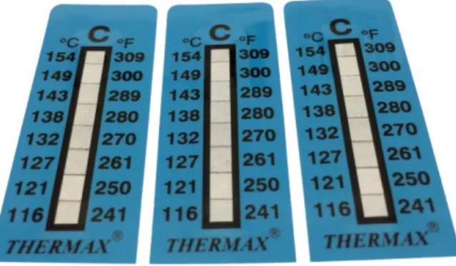
For any sensitive component or material in the vicinity of the exhaust system it is recommended to use temperature strips (Figure 10) for an easy measurement of the maximal temperature that can be expected at that location. The temperature strip is self-adhesive and changes colour depending on the maximal temperature experienced during the test interval.
Figure 10. Temperature strips for maximal temperature measurements. Other temperature ranges are also available.
A thermal imaging camera can be useful to identify the area around the exhaust system where the temperatures are significantly higher than the surroundings. Components will age and fail faster in this area and should therefore be carefully inspected allowing no flaws.
4.4
Brakes and tyres
Wheel wells are together with engine compartments the most common origin area for vehicle fires. Use the checklist below and follow the recommendations for visual inspection.
4.4.1
Checklist
The checklist shall be used to ensure that the listed items are included in the visual inspection. The succeeding inspection guideline includes considerations with respect to fire safety for the listed items.
Tyre pressures Tyre rubbers Braking systems o Brake pads o Air lines o Retarder
o Service brake pedal Hubs and bearings
Air suspension
4.4.2
Visual inspection
New vehicles/ machines
Ensure that tyre pressures are set according to specification and that no valves are leaking. Check that tyres on dual wheels are not touching one another and that no tyres can rub on any other hard surfaces. It is recommended that wheels are lifted and rotated by hand. In addition, make sure that tyres do not rub on hard points in case the air suspension would be deflated.
Inspect the braking systems. Check that air lines are tight and secured. Ensure that levers, forks and air gauges are in order and that the brakes release properly. Insert a feeler gauge between brake pad and rotor when applying the service brakes to determine proper action of the brakes. Also inspect any retarder/intarder for normal function.
Vehicles/ machines in use (in addition)
Look for signs of tyre tread separation, which is commonly found for rethreads or recaps on heavy vehicles/ machines. Also check groove depth and tyre wall condition with focus on the bead area. Notice any bumps or knots.
Inspect hubs for discoloration due to overheating. Ensure that wheel hubs have sufficient grease or, for oil filled hubs, sufficient oil and that there is no leakage. Check bearing caps, axle flange gasket and seals. Wheel bearings can be inspected by lifting the wheel and rotate and trying to rock it. There shall be minimum movement when rocking (compare with other wheels) and when rotating there shall be no roughness or unusual noise.
Inspect the braking system such that there is no leakage, no frozen or sticking air valves and no defective brakes. Also check the service brake pedal, which can be partially applied due to corrosion or debris build-up at the base of the pedal’s pivot
pin. Ensure that suspension levers are not loose and that air lines are not damaged. Make sure that electrical cables to ABS sensors etc. were inspected in section 4.1.
4.5
Other
This last subchapter for fire hazard identification include risk items not covered by the previous sections as well as identification of flaws in fire safety systems. Use the checklist below and follow the recommendations for visual inspection.
4.5.1
Checklist
The checklist shall be used to ensure that the listed items are included in the visual inspection. The succeeding inspection guideline includes considerations with respect to fire safety for the listed items.
Engine compartment insulation Belts and pulleys
Debris
Heaters in driver/passenger compartment Repair/maintenance work
Post-crash scenarios o Batteries
o Fuse boxes and electronics without preceding fuses o Fuel tank, filler and fuel lines
Fire safety systems
o Detection and suppression systems (incl. portable extinguishers) o Emergency routes
o Fire walls
4.5.2
Visual inspection
New vehicles/ machines
Anticipate post-crash fire risk scenarios based on experience from crashes and post-crash fires and knowledge of the crash-zones of the specific vehicle. Include the possibility of mechanical impacts to the underbody of the vehicle. Focus on fuse boxes, batteries, electronics without preceding fuses, fuel tanks and fluid lines in combination with hot surfaces. Pay extra attention to gas fuelled vehicles/ machines with filler and distribution in the crash-zones. Avoid electrical wiring together with fuel lines and air lines (fire triangle), which may result in a blowtorch and a fast-developing fire scenario.
Heaters should be inspected such that there is no risk of combustibles to come into contact with hot wires.
Vehicles/ machines in use
Ensure that there is no risk of insulation falling on hot parts in the engine compartment. Check also that there is no accumulation of oils or fluids in heat or sound insulations. Look for accumulation of combustible materials both in the engine compartment and at wheel arches. Make sure the intercooler is free of debris and that fans operate as normal. Include A/C fans which, for buses, could be positioned on the roof.
Check that all belts and pulleys are tight and free of wear. Look for any mechanical damage that may affect safety and operation of other components. Inspect reparations and maintenance work carefully, which could be imperfect or could have introduced new fire risks.
Ensure that any fire detection and suppression systems are working and are correctly connected with no loose or missing attachments. Check status of emergency lights and decals, emergency hammers, emergency exits and expiration date of any portable fire extinguishers. Finally inspect interior engine cover and floor hatches for sealing and security.
5
General Measures and
Recommendations
This chapter presents general fire safety measures which should be considered irrespective of identified fire hazards. Recommendations include changes to the design, passive and active fire protection systems, maintenance and cleaning procedures, as well as improved training and quality systems. First priority measures and recommendations are underlined.
The chapter is divided into three subchapters which contain the most important considerations relevant for manufacturers, operators and workshops respectively. Many recommendations are present in all three subchapters since e.g. design issues can apply to retrofitting as well as original design. Similarly, with e.g. maintenance and training, where manufacturers often provide guidelines while operators and workshops are responsible for the personnel.
5.1
Manufacturers
5.1.1
Electrical Systems
HVAC (heating, ventilation and air conditioning) speed control resistors should be encased within a protective enclosure.
o Vehicle manufacturers should demonstrate that a stalled fan does not catch fire due to overheated speed control resistors.
Keep conductors without preceding fuses as short as possible. Position main fuses already in the battery box.
Consider fuses on alternator/starter power cables. (Due to very high normal currents fuses may not prevent fires to arise, however, fuses can prevent adding energy to the hazard in case of a short circuit or
overcurrent.)
Provide a main switch adjacent to the batteries to isolate power if
required, including starter/generator circuit. Fire protection systems and some ECUs (for which complete power loss lead to loss of memory) can have a separate power supply protected by a fuse at the battery.
o The main switch should be mechanically durable, including the “key” which shall be easily accessible and clearly marked. The switch shall be capable of carrying and interrupting total possible circuit load.
o To achieve a higher safety level a pyrotechnical switch connected to e.g. the fire suppression system can be installed.
Provide adequate ventilation of lead-acid batteries. Use covers for battery terminals and starter terminal.
Cables should be secured to terminals in an adequate manner, preferably by soldering, crimping or swaging, instead of using simple clamping screws.
Ensure that military 2-pin connectors used for charging of batteries are not half moulded, which means that connector female shall be solid. (In half moulded connectors it has occurred that the pins have come loose due to unnecessary violence during contacting, causing a short circuit and resulting fire.)
Ratings of electrical devices should be conservatively chosen because components degrade over time due to operation in harsh environments, e.g. due to high ambient temperatures in the engine compartment or under the dash board.
Be aware that rubber may be conductive. Do not use any unspecified rubber for isolation purpose of the electrical system. (Rubber blocks used to avoid chafing are sometimes conductive in purpose to get rid of static charges.)
Separate electrical cabling from hydraulic and fuel hoses.
Arrange electrical cables and gas or fluid lines so as to facilitate regular visual inspection as much as is practical.
Lights exposed to road splashes should have a high ingress protection classification. (Most important in countries with much salt on the roads e.g. Nordic countries.)
Avoid any static electrical discharge by sufficient grounding/dissipation. (Especially for fluid lines.)
5.1.2
Gas and Fluid Systems
Avoid construction solutions where failed fuel lines could spray fluid onto exhaust pipes, turbo charger or other parts of the exhaust system.
Consider metal pipes or metal-braided hoses for pressurized fuel lines. Check temperature ratings of hoses and ensure that they are well away from hot surfaces. (10 °C above specified temperature range can shorten hose life by half.)
Provide mechanical impact protection for hoses and cables under the body and in wheel wells.
Ensure that auxiliary heaters, fuel hoses, gaskets, etc., endure fuel additives and alternative fuels, which will be used.
Evaluate direction of gas cylinders safety vents. Expect that jet flames of about 20 meters may originate. In general, upward or downward
directions are preferred.
Provide at least two safety vents on each cylinder, preferably activated by both temperature and pressure sensors.
Do not position fuel filler cap in front crash zone.
Consider providing emergency manual shutdowns for immediate shutdown of fuels.
Air intakes should not be located or designed such that it can easily catch leaf matter. (A lit cigarette butt drawn into an air intake apparently caused a serious truck fire in the Mt Blanc tunnel in 1999.)
5.1.3
Engine Compartment, Wheel Wells and Interior
Noise shields and mud flaps should be well away from exhaust pipes andother hot components. Shield off hot components.
Use drain holes and other suitable layout to prevent accumulation of fluids or gases.
Materials used in the engine compartment should not be able to absorb fuel or oils.
Engine compartment and battery compartment should be constructed and designed to provide appropriate maintenance access, be easily cleaned and not be damaged by high pressure hot water cleaning over time.
Use fire resistant and low smoke production materials in driver/passenger compartments.
Use fire resistant material in wheel wells. Monitor tyre pressures.
From a fire hazard perspective, consider replacing dual tyres with wide-base single tyres.
Use heat-resistant hub/wheel seals and axle flange gaskets.
From a fire hazard perspective, consider replacing oil-lubricated wheel bearings with grease-lubricated.
Monitor critical temperatures of brake systems.
5.1.4
Passive and Active Fire Protection Systems
Use fire resistant partitions between driver/passenger compartment andother areas such as the engine compartment, wheel wells, battery
compartments, and fuel storage area. (Consider weak points such as cable feedthroughs, joints, hatches, etc., and conduct fire tests if necessary) Consider not having a rear window on buses or use fire glass or laminated
glass.
Ensure automatic or easily activated smoke extraction devices on buses, e.g. opening of roof hatches.
Ensure that there are several emergency routes and adequate emergency lighting systems on buses.
Use appropriately sized fire extinguishers which are easily accessible to the driver.
o Provide fire ports/extinguisher ports for access to enclosed areas from outside, e.g. the engine compartment. (Opening the hatch will feed the fire with oxygen and may result in serious injury)
Use fire detection systems in the engine compartment and other enclosed areas.
Use automatic or semi-automatic fire suppression system in the engine compartment.
Provide driver activated or automatically activated battery isolation and shutdown of fuels.
5.1.5
Guidelines and Training Material
Use appropriate checklists for quality control, design, in-production inspection and final inspection. Provide training for inspectors and other relevant personnel.
Bodybuilders shall ensure compliance to bodybuilder directives as supplied by the chassis suppliers.
Manufacturers should always provide cleaning procedures. Ensure refuelling procedures and guidelines are provided. Consider following if drivers training is provided:
o Correct emergency response procedures. Training should also include response actions on low air pressure in tyres, changes in gauge readings, loss of drive power, smell of overheating
conditions, poor brake performance, lack of turbo power, etc. o Drivers shall always react on any warning light. Note that ABS
warning light may indicate a wheel bearing failure.
o Drivers should regularly monitor air pressure gauges, temperature gauges for overheating, coolant temperature gauge and engine oil pressure gauge.
o Drivers shall never ignore electrical misbehaviour.
o Drivers shall never ignore small crashes/impacts. Be sure to inspect exhaust end-pipes, gas fuel tanks and fuel lines.
o Drivers shall never continue driving with a flat on dual wheels or with a current tyre pressure warning.
o Ensure that drivers know how to use main breakers. Electrical systems may include several main breakers at different circuit levels.
o Drivers should check that debris has not stuck under the vehicle whenever they run over any bulky road debris. (Sparks from dragging metal parts may cause the debris to ignite.)
o Drivers should ensure that a parked or idling vehicle cannot ignite grass or dry leaves under the vehicle.
5.2
Operators
5.2.1
General
A main switch in the electrical system must be replaced due to damaged contact surfaces in case the switch has been used to interrupt a high fault current (corresponding to a short circuit).
Ensure adequate ventilation of lead-acid batteries.
Ensure covers are in place for battery terminals and starter terminal. Operators should consider checking fuel suppliers and verifying what
additives are used. The vehicle manufacturer should ensure that auxiliary heaters, fuel hoses, gaskets, etc., endure fuel additives and alternative fuels, which are used.
Evaluate direction of gas cylinders safety vents and the possible impact on operation environment and surroundings. Expect that jet flames of about 20 meters may originate.
Do temperature measurements on surrounding components for retrofitted exhaust after-treatment systems.
Where the climatic conditions permit, consider using non-glycol type of coolants. (A typical scenario is that there is a leaking hose which allows the coolant to leak onto a hot surface. Over a period of time the water content of the coolant evaporates, leaving a resin behind which contains ethylene glycol, and which can be ignited under certain conditions.) Shield off hot components.
Monitor tyre pressures.
Monitor critical temperatures of brake systems.
5.2.2
Passive and Active Fire Protection Systems
Check the partitions between driver/passenger compartment and otherareas such as the engine compartment, wheel wells, battery
compartments, and fuel storage area. (Consider weak points such as cable feedthroughs, joints, hatches, etc., and conduct fire tests if necessary) Regularly control function of smoke extraction devices on buses, e.g.
opening of roof hatches.
Regularly control function of emergency lighting systems on buses. Regularly control function of emergency routes, e.g. availability of
emergency hammers.
Ensure fire extinguishers are in place and easily accessible to the driver. Use adequate fire detection systems in the engine compartment and other
enclosed areas.
Use automatic or semi-automatic fire suppression system in the engine compartment.
Evaluate main breakers and ensure that drivers know how to use them. Electrical systems may include several main breakers at different circuit levels.
5.2.3
Cleaning and Inspection
Clean engine, transmission and surroundings regularly allowing no build-up of flammable deposits. Regular and thorough cleaning is seen as being critical in reducing the risk of fires!
Compressed air can in general be used to blow residue out of alternators and starter.
Clean the battery surfaces and terminals. (Make sure terminal covers are in place afterwards)
Check that the radiator, intercooler and oil cooler are free of debris. Ensure all fluid levels are correct.
Check and adjust wheel bearings regularly.
Use appropriate checklists for driver inspection (pre/post trip) and extended whole vehicle inspection. Provide training for inspectors and drivers.
Ensure that all faults that are found during operation are recorded in the driver’s defect reporting system and that all defect reports and repairs are documented and filed.
Operators shall keep up to date with manufacturers’ service/cleaning/inspection guidelines.
5.2.4
Training
All drivers should be trained in the correct emergency response
procedures, including operation of fire extinguishers and other fire safety devices.
Training should also include response actions on low air pressure in tyres, changes in gauge readings, loss of drive power, smell of overheating conditions, poor brake performance, lack of turbo power, etc. Drivers should:
o Always react on any warning light. Note that ABS warning light may indicate a wheel bearing failure.
o Regularly monitor air pressure gauges, temperature gauges for overheating, coolant temperature gauge and engine oil pressure gauge.
o Never ignore electrical misbehaviour.
o Never ignore small crashes/impacts. Be sure to inspect exhaust end-pipes, gas fuel tanks and fuel lines.
o Never continue driving with a flat on dual wheels or with a current tyre pressure warning.
o Check that debris has not stuck under the vehicle whenever they run over any bulky road debris. (Sparks from dragging metal parts may cause the debris to ignite.)
o Ensure that a parked or idling vehicle cannot ignite grass or dry leaves under the vehicle.
Ensure that drivers know how to use main breakers. Electrical systems may include several main breakers at different circuit levels.
Keep largest possible separations between parked vehicles/ machines to minimize the risk of fire propagation.
Provide training focused on new hazards related to electrical charging and refuelling of different fuel gases.
5.3
Workshops
5.3.1
Design of Retrofitting and Repairs
5.3.1.1
Electrical Systems
HVAC (heating, ventilation and air conditioning) speed control resistors should be encased within a protective enclosure.
Keep conductors without preceding fuses as short as possible. Position main fuses already in the battery box.
A main switch in the electrical system must be replaced due to damaged contact surfaces in case the switch has been used to interrupt a high fault current (corresponding to a short circuit).
Provide adequate ventilation of lead-acid batteries. Put covers for battery terminals and starter terminal.
Use non-conductive and resistant securement methods for cables.
Cables should be secured to terminals in an adequate manner, preferably by soldering, crimping or swaging, instead of using simple clamping screws.
Ratings of electrical devices should be conservatively chosen because components degrade over time due to operation in harsh environments, e.g. due to high ambient temperatures in the engine compartment or under the dashboard.
Be aware that rubber may be conductive. Do not use any unspecified rubber for isolation purpose of the electrical system. (Rubber blocks used to avoid chafing are sometimes conductive in purpose to get rid of static charges.)
Separate electrical cabling from hydraulic and fuel hoses.
Arrange electrical cables and gas or fluid lines so as to facilitate regular visual inspection as much as is practical.
Lights exposed to road splashes should have a high ingress protection classification. (Most important in countries with much salt on the roads e.g. Nordic countries.)
Avoid any static electrical discharge by sufficient grounding/dissipation. (Especially for fluid lines.)
5.3.1.2
Gas and Fluid Systems
Avoid construction solutions where failed fuel lines could spray fluid onto exhaust pipes, turbo charger or other parts of the exhaust system.
Consider metal pipes or metal-braided hoses for pressurized fuel lines. Check temperature ratings of hoses and ensure that they are well away from hot surfaces. (10 °C above specified temperature range can shorten hose life by half.)
Ensure that fuel hoses, gaskets, etc., endure fuel additives and alternative fuels, which will be used.
Evaluate direction of gas cylinders safety vents. Expect that jet flames of about 20 meters may originate. In general, upward or downward
directions are preferred.
Do not position fuel filler cap in front crash zone.
Do temperature measurements on surrounding components for retrofitted exhaust after-treatment systems.
Use exhaust end-pipes without joints.
5.3.1.3
Engine Compartment, Wheel Wells and Interior
Noise shields and mud flaps should be well away from exhaust pipes and other hot components.
Shield off hot components.
Use drain holes and other suitable layout to prevent accumulation of fluids or gases.
Materials used in the engine compartment should not be able to absorb fuel or oils.
Use fire resistant and low smoke production materials in driver/passenger compartments.
Use fire resistant material in wheel wells.
Use heat-resistant hub/wheel seals and axle flange gaskets.
Use fire resistant partitions between driver/passenger compartment and other areas such as the engine compartment, wheel wells, battery
compartments, and fuel storage area. (Consider weak points such as cable feedthroughs, joints, hatches, etc.)
5.3.2
Maintenance, Cleaning and Quality Systems
Maintenance procedures must assure that parts and components are putback in same positions and that cables and hoses are secured correctly. Make sure conducting rubber is not used where it is not supposed to. Check and adjust wheel bearings.
Compressed air can in general be used to blow residue out of alternators and starter.
Clean the battery surfaces and terminals.
Check that the radiator, intercooler and oil cooler are free of debris. Ensure all fluid levels are correct.
Never ignore electrical misbehaviour.
Never ignore small impacts. Be sure to inspect exhaust end-pipes, gas fuel tanks and fuel lines.
Ensure that all faults that are found and repairs are documented and filed. Provide training focused on new hazards related to alternative fuels. Use appropriate checklists for vehicle inspections. Provide training for
inspectors and other relevant personnel.
Workshops shall keep up to date with manufacturers’ service/cleaning/inspection guidelines.
6
Report
The fire risk management report shall as a minimum include the following information:
• Name and affiliation of inspector
• Date and identification number of the fire risk management report
• Vehicle/ machine type, manufacturer, model, model year, mileage and last service/inspection.
• Date of fire risk management
• Detailed description of all identified fire hazards, sorted with respect to hazard area (enclosure)
• Photos from the inspection
• Name and address of vehicle manufacturer or operator (decision makers for risk reduction measures)
• Action plan (or motivation why the risk is considered acceptable) for each estimated fire risk
Appendix A – Typical Fire Causes
Electrical
Sparks and electric arc
Static discharge grounding/dissipationInsufficient
Loose contact Fault current Resistance heat Fault current Insulation fault Abrasion Thermally damaged insulation Corrosion damaged insulation Saltwater, Organic dust External mechanical force Overcurrent
Improper dimensioning of cables, connectors, fuses, and PCBs Overloaded circuits
Seized starter relays
Contact resistance Oxidation in joints and terminals Damaged conductors/connectors Poor mounted connectors, loose contact High loads (e.g. lights
or HVAC resistors) Improper dimensioning of
cable feedthroughs
Batteries
Ignition of
hydrogen gas Charging
Thermal runaway
External mechanical or thermal energy High currents (Short
circuit)
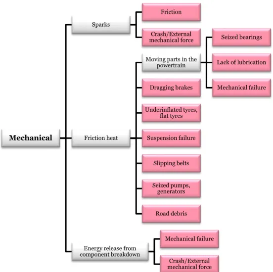
Mechanical Sparks Friction Crash/External mechanical force Friction heat
Moving parts in the powertrain Seized bearings Lack of lubrication Mechanical failure Dragging brakes Underinflated tyres, flat tyres Suspension failure Slipping belts Seized pumps, generators Road debris
Energy release from component breakdown
Mechanical failure Crash/External mechanical force
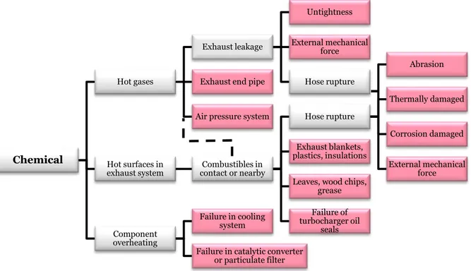
Chemical Hot gases Exhaust leakage Untightness External mechanical force Hose rupture Exhaust end pipe
Air pressure system
Hot surfaces in
exhaust system contact or nearbyCombustibles in
Hose rupture Abrasion Thermally damaged Corrosion damaged External mechanical force Exhaust blankets, plastics, insulations Leaves, wood chips,
grease Failure of turbocharger oil seals Component overheating Failure in cooling system
Failure in catalytic converter or particulate filter
Appendix B – Statistics
Bus Fires in Australia
Figure 14 Bus fires in New South Wales, Australia, in 2016. Source: OTSI, Bus Safety Report: Bus fires in New
South Wales in 2016, Australia, 2017.
Figure 15 Reviewed Australian bus fire incidents between 2009 and 2013. Approximately 85 bus fire incidents were reviewed, but detailed information on fire origin was only found on 27 incidents. Source: Bus Industry Confederation Inc., Fire Mitigation Advisory, Australia, 2014.
0 10 20 30
Engine unknown Wheel well other Tyre Electrical body Electrical engine Mechanical engine Fluid engine Brakes Number of Incidents 0 2 4 6 8 10
Engine mechanical coolant Engine mechanical fuel Tyre brakes Engine mechanical oil Tyre Engine electrical Engine mechanical
Bus fires in the USA
Figure 16 U.S. bus and school bus fires, annual averages between 1999-2003: Fire causes. Source: M. Ahrens,
Vehicle fires involving buses and school buses, NFPA, US, 2006.
Figure 17 U.S. bus and school bus fires, annual averages between 1999-2003: Item first ignited. Source: M. Ahrens, Vehicle fires involving buses and school buses, NFPA, US, 2006.
0 100 200 300 400 500 600 700 800 900 Design, manufacturing or installation…
Mechanical failure - backfire Operational deficiency Fire spread Mechanical failure - worn out Electrical failure - defective, worn…
Misuse of material or product Mechanical failure - leak/break Electrical failure - other Mechanical failure - other
Number of Incidents
0 100 200 300 400 500 600 700 800 900 Dust, fiber or lint
Mattress/pillow Rubbish/trash Film or residue Magazine and paper Belt (drive, conveyor or V-) Multiple items Seat or furniture Tire Unclassified Flammable liquid or gas, piping or filter Electrical wire or cable insulation
Bus Fires in Finland
Figure 18 Bus fires in 2010-2011 in Finland. Source: E. Kokki, Bus Fires in 2010-2011 in Finland, FIVE 2012, Chicago.
Responsible Parties in Bus Fires in the USA
Figure 19 Between 2002-2006 approximately 120 bus fires were investigated in the USA. This diagram shows the responsible party in fires related to electrical and high-pressure fluid line failures. Source: Public Transportation Safety Board, Bus fire analysis – Investigations 2002 thru 2006, US, 2008. 0 5 10 15 20 25 30 35 Other Intentional Unknown Fuel and oil leaks Failure of an additional heater Overheated brakes or bearings Electrical failure
Number of Incidents
0 20 40 60
Lack of skill - operator Lack of training - operator Lack of supervision Lack of training - maintainer Lack of skill - supervisor Failure to detect - maintainer Unknown Lack of skill - maintainer Manufacturer design (routing etc.) Random failure
Motorcoach Fires in the USA
Figure 20 Reported ignition points of motorcoach fires in the US between 1995-2008. Source: N. R. Meltzer, G. Ayres and M. Truong, Motorcoach Fire Safety Analysis: The Causes, Frequency, and Severity
of Motorcoach Fires in the United States, FIVE 2012, Chicago.
0 20 40 60 80 100
Other cause - unspecified Dirty block Auxiliary heaters - fuel Other cause - fuel system Auxiliaries - interior Alternator Other cause - other area Exhaust system Auxiliary heaters - engine Air conditioners Other cause - wheel well Other cause - engine Electrical - interior Electrical - other area Fluid lines - unspecified Fluid lines - engine Electrical - unspecified area Electrical - engine Wheel/hub bearing Turbochargers Tyres Brakes Number of Incidents
Automobile Fires in the USA
Figure 21
Figure 22 Non-intentional automobile fires in the US between 2006-2010. Statistics are based on about 450 000 reported automobile fire incidents, including cars, buses, trucks, etc. Source: M. Ahrens,
Automobile Fires in the U.S.: 2006-2010 Estimates, FIVE 2012, Chicago.
0% 20% 40% 60% 80%
Unclassified area of origin Fuel tank or fuel line Cargo or trunk area Exterior surface Unclassified vehicle area Passenger area Engine area, running gear or
wheel area Fires Deaths 0% 20% 40% 60% 80% Smoking material Exposure fire Collision or overturn Electrical failure or malfunction Mechanical failure or malfunction Engine area, running gear or wheel well Passenger area Fuel tank or fuel line
Vehicle Fires in Swedish Underground Mines
A
Figure 23 Vehicle fires in underground mines 1988-2010. Source: R. Hansen, Investigation on fire causes
and fire behaviour – Vehicle fires in underground mines in Sweden 1988-2010, Mälardalen University,
Sweden, 2013.
Fires in Parked Vehicles, New Zealand
Figure 24 Vehicle fires in New Zealand parking buildings from 1995 to 2003. Source: Y. Li, Assessment of
Vehicle Fires in New Zealand Parking Buildings, University of Canterbury, New Zealand, 2004.
0 20 40 60 80 100
Scrubber HeadlightMuffler Electrical switchMagnetic valve Electrical boxStart engine Electrical RelayUnknown Electrical contactBattery EngineTurbo Brake Exhaust pipe Electrical - unknown Mechanical - unknownElectrical cable
Number of Incidents
0 5 10 15 20 25 30
Deliberately litCarelessness Unknown Other - backfireOther - friction Other - exposure fire Mechanical - lack of maintenance Mechanical - equipment overloadedMechanical - installation deficiency Mechanical - operator fault Mechanical - part failure, leak or breakElectrical - other Electrical - short circuit and earth fault
Through our international collaboration programmes with academia, industry, and the public sector, we ensure the competitiveness of the Swedish business community on an international level and contribute to a sustainable society. Our 2,200 employees support and promote all manner of innovative processes, and our roughly 100 testbeds and demonstration facilities are instrumental in developing the future-proofing of products, technologies, and services. RISE Research Institutes of Sweden is fully owned by the Swedish state.
RISE Research Institutes of Sweden AB Box 857, SE-501 15 BORÅS, Sweden Telephone: +46 10 516 50 00
E-mail: info@ri.se, Internet: www.ri.se