• No results found

2010:42 Using the EPRI Risk-Informed ISI Methodology on Piping Systems in Forsmark 3

N/A
N/A
Protected

Academic year: 2021

Share "2010:42 Using the EPRI Risk-Informed ISI Methodology on Piping Systems in Forsmark 3"

Copied!
150
0
0

Loading.... (view fulltext now)

Full text

(1)

Research

2010:42

Using the EPRI Risk-Informed ISI

Metho-dology on Piping Systems in Forsmark 3

Authors: Patrick O’Regan

Jim Moody Jan Lötman Johan Sandstedt

(2)
(3)

Title: Using the EPRI Risk-Informed ISI Methodology on Piping Systems in Forsmark 3 Report number: 2010:42

Author: Patrick O’Regan1), Jim Moody2), Jan Lötman3) and Johan Sandstedt4) 1)Electric Power Research Institute, Knoxville, USA. ,

2)JHM Consulting, Strafford, USA. 3)Forsmarks Kraftgrupp AB. 4)Risk Pilot AB, Stockholm Date: December 2010

This report concerns a study which has been conducted for the Swedish

Radiation Safety Authority, SSM. The conclusions and viewpoints

present-ed in the report are those of the author/authors and do not necessarily

coincide with those of the SSM.

SSM Perspective

Background

In the SSM regulation SSMFS 2008:13, it is stated that the selection of

lo-cations for inspection of mechanical components shall be based upon the

risk for core damage or the risk of release of radioactive substances. Both

qualitative and quantitative measures of the relative risk are allowed to be

used. So far only the PWRs in Sweden are using a quantitative procedure

to evaluate the risk whereas all the BWRs are using a qualitative risk

pro-cedure based upon the so-called damage index and consequence index.

All Nuclear Power Plants in Sweden have a fairly detailed PSA analyses

and it is now of interest to find out if such PSA analyses can assist the

selection of piping components for inspection also for BWRs. The

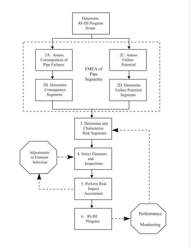
EPRI-procedure is a semi-quantitative methodology which uses the PSA

infor-mation together with the assessment of the failure potential from different

degradation mechanisms to perform a risk evaluation.

Objectives of the project

The principal objective of the project is to use the EPRI procedure for

risk-informed In-Service Inspection to select piping components for

inspection and compare the outcome with the presently used qualitative

risk procedure on Forsmark 3.

Results

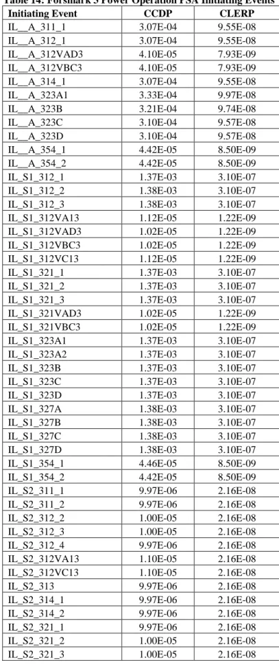
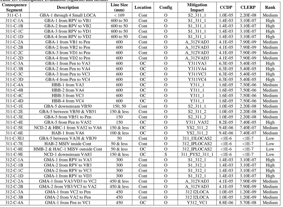
Five piping systems in Forsmark 3 were chosen for the pilot study, main

steam 311, feedwater line 312, residual heat removal 321, low pressure

injection 323 and the condensate system 462. The results of the risk

ranking show a general similarity between the EPRI procedure and the

present qualitative risk procedure. Certain differences have been found,

for example:

• No pipe system were assigned high consequence (consequence

index 1) with the qualitative risk procedure whereas several pipe

segments using the EPRI procedure were ranked to be high

conse-quence based on the plant PSA analysis.

(4)

In system 462, several pipe segments had a potential for Flow Ac-celerated Corrosion (FAC) which together with the consequence

ranking were categorized as high risk. The same segments were

outside the scope of the present qualitative risk procedure

be-cause the segments were located outside the containment in areas

where no consequence index are defined.

Effects on SSM supervisory and regulatory task

The results of this project will be used by SSM in the improvement of the

selection procedure for locations of inspection of piping components.

Project information

Project leader at SSM: Björn Brickstad

Project number: SSM 2009/1641

Project Organization: EPRI has managed the project with Patrick O’Regan

as the project manager. Jan Lötman and his co-workers at Forsmarks

Kraft-grupp AB have supplied plant information to the project with the help of

Johan Sandstedt, Risk Pilot AB for the PSA input.

(5)
(6)

Table of Contents

1

Introduction ... 1

1.1

Objective ... 1

1.2

Overview of EPRI RI-ISI Methodology ... 1

1.3

Overview of SKIFS Methodology ... 3

2

Evaluation Scope ... 6

3

Consequence Evaluation ... 7

3.1

Forsmark 3 PSA ... 7

3.2

Configurations, Impact Group and Consequence Rank ... 7

3.3

Initiating Event Evaluation ... 10

3.4

Isolable LOCA (ILOCA) and Potential LOCA (PLOCA) inside Containment ... 11

3.5

Isolable LOCA (ILOCA) and Potential LOCA (PLOCA) outside Containment .... 12

3.6

Spatial and Internal Flooding ... 14

3.7

Success Criteria ... 15

3.8

Loss of Mitigation (Standby Systems) ... 16

3.8.1

RHR (321) Low Pressure Train ... 17

3.8.2

Low Pressure Injection (323) Suction Piping ... 17

3.8.3

Low Pressure Injection Discharge Piping ... 18

3.9

Combination Impact (Initiator and mitigation) ... 19

3.10

Containment Performance ... 20

3.11

Shutdown Configurations ... 20

3.12

External Events ... 22

3.13

Consequence Evaluation Results ... 23

3.14

Comparison Summary ... 24

4

Failure Potential Evaluation ... 38

4.1

Background ... 38

4.1.1

Degradation Mechanism Summary... 38

4.1.2

Degradation Mechanism Categories ... 42

4.2

Main Steam (311) ... 44

4.3

Feedwater Lines (312) ... 46

4.4

Residual Heat Removal (321) ... 50

4.5

Low Pressure Injection (323) ... 54

4.6

Condensate (462) ... 58

4.7

Service History Review ... 61

4.8

Comparison Summary ... 61

5

Risk Ranking ... 83

6

Element Selection ... 90

7

Risk Impact Assessment ... 94

7.1

Methodology ... 94

7.2

Risk Analysis and Results ... 96

8

Summary ... 99

References ... 100

(7)

1

Introduction

1.1 Objective

The objective of this project is a pilot plant demonstration of the EPRI RI-ISI Methodology to

selected systems at Forsmark, Unit 3 (F3). As described in section 2, five systems were selected

for evaluation. These systems were selected because they allow this project to focus on a

number of issues of interest in developing a RI-ISI methodology and RI-ISI program. This

includes the following:

Several different types of degradation may be identified,

Several different types of “consequence of failure” may be identified,

Different types of safety systems are evaluated

Non-safety systems are evaluated

Using the results of this application, insights and comparisons between SKIFS and the EPRI

methodologies’ are provided including the following:

Consequence of pressure boundary failure (PBF) as described in Section 3.14.

Degradation mechanism evaluation as described in Section 4.8.

Risk ranking as described in Section 5.

Element selection for inspection as described in Section 6.

Risk impact as described in Section 7.

An overview of both the EPRI and SKIFS methodologies are provided in the following sections.

1.2 Overview of EPRI RI-ISI Methodology

The EPRI Risk-informed inservice inspection (RI-ISI) methodology [1] was developed as an

alternative to deterministic ISI programs. The EPRI RI-ISI methodology, which is depicted in

Figure 1, is implemented by following a six step process:

1. Definition of RI-ISI program scope.

2. Failure Mode and Effects Analysis (FMEA) of Pipe Segments.

a. Evaluation of consequences of pipe failures.

b. Evaluation of pipe failure potential.

3. Characterization of risk segments.

4. Inspection element selection.

5. Evaluation of risk impact of changes to the inspection program.

6. Incorporation of long term RI-ISI program.

(8)

The first step is to decide on the scope of the RI-ISI program. Options include:

Large scope applications that include Safety Class 1, 2, and 3 and other piping systems

important to safety;

Selection of one or more Classes of piping (e.g. reactor coolant pressure boundary), or

Selection of one or more individual piping systems.

It is assumed that any piping or systems not selected for the RI-ISI program scope will be

retained within the current plant inservice inspection program. An additional decision that must

be made to set the scope of the RI-ISI program is to decide whether piping systems and

degradation mechanisms covered within other inspection programs, will be incorporated into the

RI-ISI program, or left unchanged. Those augmented inspection programs that may be typically

subsumed are discussed in more detail in Section 6.5 of Reference [1].

The second step is to perform an FMEA of the piping systems within the RI-ISI program scope.

In Figure 1, this step is broken down into four distinct sub-steps as this is where most of the

resources are applied in developing and implementing a RI-ISI program. The FMEA is normally

performed on a system by system basis and leads to the definition of piping segments that have

common potential for failure and common consequence potential. Segments with the same

failure potential and same consequence potential are combined into risk segments in step 3.

While the analysis is conducted on a segment basis, it is for ease of use rather than being a

technical component of the analyses. As such, differences in segment definition or segment

boundary definition will have no impact on the final results for applications using the EPRI

RI-ISI methodology.

The consequences of pipe rupture are measured in terms of the conditional probability of core

damage given a pipe rupture (CCDP) and the conditional probability of large early release given

a pipe rupture (CLERP). These measurements require quantitative risk estimates obtained from

the plant specific PSA models available for the given plant. Application of this step is further

discussed in Section 3 of this report.

In a similar fashion, failure potential of each pipe location needs to be assessed in terms of the

relative potential for pipe rupture. By evaluating physical conditions needed for various

degradation mechanisms to be operative against plant-specific operating and material conditions,

failure potential can be correlated to quantitative estimates of pipe rupture frequency derived

from service experience. Application of this step is further discussed in Section 4 of this report.

As discussed previously, piping segments with the same failure potential and consequence

potential are defined as “risk segments.”

Pipe elements (e.g. welds) within each segment are candidate locations to be selected for the

inspection program based on the risk characterization of the segment to which each element

belongs. In step 3, each segment is placed onto the appropriate place on the EPRI segment risk

characterization matrix as described in Figure 2 based on three broad categories of failure

potential (high, medium, or low) and four broad categories of consequence potential (high,

medium, low, or none). Based on the combination of failure potential and consequence

categories, each location on the risk matrix is assigned to one of three broad risk regions that are

correlated to ranges of absolute levels of core damage frequency (CDF) and large early release

frequency (LERF). Application of this step is further discussed in Section 5 of this report.

(9)

In step 4, the revised set of inspection requirements is defined. Specific locations on the risk

matrix are selected for the inspection program based on the segment’s risk ranking and a set of

practical considerations that bear on the feasibility and effectiveness of the specific inspection.

For those locations selected for NDE inspections, the inspections are focused on the type of

degradation mechanism identified in step 2. The ability to focus the examination on specific

damage mechanism(s) enhances the effectiveness of the retained inspections.

As a final analysis step, it must be shown that the changes in risk due to changes in the

inspection program do not pose a significant risk impact as determined by changes in CDF or

LERF. The EPRI approach to RI-ISI has been designed to ensure that risk impacts associated

with enhancements to the inspection program, such as those that will be brought about by

focusing inspections on high and medium risk locations, and those from gearing the

examinations to those damage mechanisms most likely to be observed, will exceed any risk

increases associated with eliminating inspections from current deterministic based programs.

Hence, significant adjustments to the locations that were initially selected, in order to

demonstrate that risk impact requirements are not exceeded, are not anticipated. Nonetheless, in

this step, it must be confirmed that the initial selection of elements for the RI-ISI program does

not produce an unfavorable and unacceptable risk impact.

1.3 Overview of SKIFS Methodology

The SKIFS approach is very similar to EPRI’s in that both consequence and degradation is

evaluated and then welds are ranked in a risk matrix (see Figure 3). As shown in Figure 3, the

EPRI and SKIFS matrices are mirror images of each other. This is because the SKIFS

consequences are ranked from left to right as High (1), Medium (2) and Low (3) where as the

EPRI ranking in Figure 2 is just the opposite. This has no technical impact, only visual effects.

The following summaries the SKIFS evaluation steps:

Consequence index (KI) is determined based on proximity of piping to the reactor vessel and

isolation valves. Section 3.14 describes the criteria in more detail where the results of both

the EPRI and SKIFS evaluations are compared.

Degradation potential or damage index (SI) is determined based on degradation mechanism

potential and mechanical fatigue. Section 4.8 describes the criteria in more detail where the

results of both the EPRI and SKIFS evaluations are compared.

Inspection groups are determined using the risk matrix in Figure 3. Section 5 describes the

criteria in more detail where the risk ranking results for both EPRI and SKIFS are compared.

Elements are selected for inspection. Sections 5 and 6 describe the criteria in more detail

where the results for both EPRI and SKIFS are compared.

This study is based upon F3 implementation of SKIFs guidance as well as other consideration as

documented in the PMT program and provided in Reference 6.

(10)
(11)

Figure 2: EPRI Matrix for Segment Risk Characterization

Consequence Index (KI)

1

2

3

Damage

Index

(SI)

I

Inspection

Group

A

Inspection

Group

A

Inspection

Group

B

II

Inspection

Group

A

Inspection

Group

B

Inspection

Group

C

III

Inspection

Group

B

Inspection

Group

C

Inspection

Group

C

Note that in practice there is also a “None” consequence index utilized by SKIFS similar to EPRI

(12)

2

Evaluation Scope

This scope of this study encompasses five systems and is based upon F3 implementation of

SKIFs guidance as well as other consideration as documented in the PMT program and provided

in Reference 6.

The systems selected for the F3 pilot study and reasons for selecting these systems are provided

below:

311 “Main Steam” from the reactor vessel to the 421 system in the Turbine Building

 Postulated failures may result in a LOCA event

 Postulated failures may result in a plant transient

 Piping located inside and outside containment

 High pressure / temperature steam environment

 Normally operating system

 Safety related and non safety related system

312 “Feedwater Lines” from the 463 system in the Turbine Building to the reactor vessel

 Postulated failures may result in a LOCA event

 Postulated failures may result in a plant transient

 Piping located inside and outside containment

 High pressure / temperature water environment

 Normally operating system

 Safety related and non safety related system

321 “Residual Heat Removal” a closed loop system that takes suction from the reactor

vessel and returns to the reactor through the 312 system injection path

 Postulated failures may result in a plant transient

 Postulated failures may impact mitigative (standby low pressure portion of

system) equipment

 Piping located inside and outside containment

 Portions of system experience a high pressure / temperature water environment

 Portions of system experience a low pressure / temperature water environment

 Portion of system normally operating

 Portion of system normally in standby

 Safety related and non safety related system

323 “Low Pressure Injection” takes water from the suppression pool and injects into the

reactor vessel

 Postulated failures may impact mitigative (standby ECCS function) equipment

 Piping located inside and outside containment

 Low pressure / temperature water environment

 System normally in standby

(13)

462 “Condensate” takes water from the condenser hot well and supplies the feedwater

system (312) via system 463

 Postulated failures may result in a plant transient

 Piping located outside containment

 Moderate pressure / temperature water environment

 System normally operating

 Non-safety related system

3

Consequence Evaluation

The methodology details used in this consequence evaluation of the five Forsmark 3 systems is

contained in Reference 1.

3.1 Forsmark 3 PSA

The Forsmark 3 power operation PSA includes both Level 1 and 2 models, which allows core

damage frequency (CDF) and large early release frequency (LERF) to be estimated. The list of

initiating events includes internal transients and several loss of coolant accidents (LOCA) both

inside containment and outside containment. Internal flood and fire initiating events are also

included in the model. The following summarizes the power operation PRA results:

Table 1: Forsmark Evaluation Scope

Initiating Event Group

CDF

LERF

All Internal Events (Transient, LOCA)

1.7E-5

2.9E-8

Internal Flood Events

3.3E-8

NA (1)

Internal Fire Events

1.8E-7

NA (1)

External Events

8.7E-6

3.1E-9

(1) Not calculated, but LERP

)CD

< 0.1

Forsmark 3 also has a shutdown model, which is capable of estimating CDF for internal

initiating events. This model includes several human induced LOCA events identified from

evaluating outage test & maintenance activities. Pipe breaks are not modeled, but these are

judged to be much less likely during shutdown and to support outage risk management, it is the

human induced events that are important to evaluate. The estimated CDF for a typical refueling

outage is on the order of 5E-5/year.

3.2 Configurations, Impact Group and Consequence Rank

The applicable configurations and consequence evaluation impact groups for each system during

power operation are identified below per the requirements of the EPRI RI-ISI Methodology:

(14)

Table 2: System Configurations and Evaluation Group

System

Configurations (Impact Group)

311 – Main Steam

Operating (initiating event evaluation)

312 – Main Feedwater

Operating (initiating event evaluation)

321 – Residual Heat Removal (high pressure)

Operating (initiating event evaluation) (1)

321 – Residual Heat Removal (low pressure)

Standby (loss of mitigation evaluation) except RCPB (2)

323 – Low Pressure Injection

Standby (loss of mitigation evaluation) except RCPB

462 – Condensate

Operating (initiating event evaluation)

(1) The high pressure RHR system is normally operating to support the chemical inspection

(cleanup) function. This system is also credited in the PSA model as supporting the heat

removal function.

(2) The low pressure RHR system is normally isolated from the reactor coolant system and

used during plant shutdown when going to cold shutdown. This system is not credited in

providing a mitigative function in the Forsmark 3 power operation PSA model (heat

removal function). However, LOCA initiators due to loss of pressure boundary integrity

in this system are evaluated and included in the power operation PSA model.

The applicable impact group evaluations are further summarized below for each system:

Table 3: Applicable Evaluation Groups

System

Initiating Event Evaluations

Loss of Mitigation Evaluations

311 – Main Steam

LOCA, ILOCA, I2LOCA

Not Applicable (1)

312 – Main Feedwater

LOCA, ILOCA, I2LOCA

Not Applicable (1)

321 – RHR (high pressure)

LOCA, ILOCA, I2LOCA

Not Applicable (1)

321 – RHR (low pressure)

LOCA, ILOCA, I2LOCA

Shutdown (2)

323 – LPI

LOCA, PLOCA, P2LOCA

Standby – suction line from suppression pool

Demand – pipe discharge piping

462 – Condensate

TF

Not Applicable (1)

(1) Pressure boundary failure during mitigation exposure time is unlikely, given that failure

did not cause an initiating event. Initiating event evaluation is bounding.

(2) Since the low pressure RHR train is not credited in the power operation PSA (i.e. low or

no consequence of failure), it is evaluated during the plant shutdown configuration when

it may be demanded to respond to events that could occur during shutdown.

LOCA = pressure boundary failure in piping connected to the reactor that is not isolable or

isolated

ILOCA = isolable pressure boundary failure with normally open valve connected to reactor.

Examples of ILOCA pipe segments are pipe segments located upstream of normally

open feedwater (312) check valves VA3, VB3, VC3 and VD3.

PLOCA = potential LOCA requires rupture of normally closed valve between reactor and piping.

Examples of PLOCA pipe segments are pipe segments located upstream of normally

closed LPI (323) check valves VA5, VB5, VC5 and VD5.

(15)

I2LOCA = similar to ILOCA except that 2 normally open valves are available to isolate the pipe

failure. Examples of I2LOCA pipe segments are pipe segments located upstream of

normally open feedwater (312) check valves VA2 and VC2. These pipe segments are

also upstream of normally open check valves VA3, VB3, VC3 and VD3.

P2LOCA = similar to PLOCA except that 2 normally closed valves must rupture. Examples of

P2LOCA pipe segments are pipe segments that are upstream of normally closed LPI

(323) outside containment MOV VA4, VB4, VC4, and VD4. These pipe segment are

also upstream of normally closed valves VA5, VB5, VC5 and VD5.

TF = total loss of feedwater initiating event

Standby = pipe failure is postulated to occur with the system in standby, in this case, resulting in

a forced plant shutdown (e.g. Technical Specification limitation).

Demand = pipe failure postulated to occur during an independent system demand (e.g. during a

LOCA demand).

Once the applicable configuration and impact group has been determined, the plant-specific PSA

can be used to determine a consequence rank. The consequence ranking philosophy is

summarized as follows:

High Consequence: Pressure boundary failures resulting in events that are important

contributors to plant risk and/or pressure boundary failures which significantly degrade

the plant’s mitigative ability.

Low Consequence: Pressure boundary failures resulting in anticipated operational events

and/or pressure boundary failures which do not significantly impact the plant’s mitigative

ability.

Medium Consequence: This category is included to accommodate pressure boundary

failures which fall between the high and low rank.

None Consequence: This category includes failures that have no affect on risk; an

example is “abandoned-in-place” piping.

The ranges used to quantitatively define each category are shown below.

Consequence Category

Corresponding CCDP

Range

Corresponding CLERP

Range

HIGH

CCDP > 1E-4

CLERP > 1E-5

MEDIUM

1E-6 < CCDP < 1E-4

1E-7 < CLERP < 1E-5

(16)

3.3 Initiating Event Evaluation

Initiating event CCDP (conditional core damage probability) and CLERP (conditional large early

release probability) are key inputs to assessing the consequences of pressure boundary failures.

The following lists the initiating event results from the F3 PSA model:

Table 4: Initiating Event CCDP & CLERP

Initiating Event

CCDP

CLERP

Consequence

TF – Loss of Feedwater and Main Condenser

8.9E-6

2.1E-8

Medium

TT – Loss of Main Condenser

8.0E-6

2.1E-8

Medium

TS – Scram

7.9E-6

2.1E-8

Medium

S2 – Small LOCA (311, 312, 321, 323)

1.0E-5

2.2E-8

Medium

S1 – Medium LOCA (311, 312, 321, 323)

1.4E-3

3.1E-7

High

A – Large LOCA (311, 312, 321, 323)

3.2E-4

1.0E-7

High

As shown, per the EPRI RI-ISI methodology, medium and large LOCA is a High Consequence

and small LOCA is Medium Consequence. Pipe sizes are defined in the Forsmark 3 PSA based

on success criteria impact. As shown below, the number of auxiliary feedwater (327, AFW)

trains required for successful inventory control determines the upper bound for small LOCA. In

the case where AFW does not succeed, the reactor must be depressurized for a small LOCA to

allow inventory control with the low pressure injection (LPI) system. The upper bound break

size for medium LOCA or the lower bound break size for large LOCA is determined by that

break size that guarantees depressurization by the break itself.

Table 5: Success Criteria used to Determine LOCA Break Size

Initiating Event

AFW

Reactor Depressurization for LPI

S2 – Small LOCA

1 of 4

Yes

S1 – Medium LOCA

2 of 4

Yes

A – Large LOCA

2 of 4

Guaranteed Success

Other success criteria such as reactivity control and heat removal are the same for all LOCA

initiators in the Forsmark 3 PSA.

The break sizes also depend on whether the break occurs on top of the reactor vessel (steam) or

on the bottom of the reactor vessel (water) or in between. The Forsmark 3 PSA considers three

potential locations (1) Top (2) Middle and (3) Bottom as summarized below:

Table 6: LOCA Locations and Sizes

System

Location

S2

S1

A

311 – Main Steam

Top

< 169 mm

NA

≥ 169 mm

312 – Feedwater

Middle

< 94 mm

94 to 208 mm

≥ 208 mm

321 – RHR

Middle

< 94 mm

94 to 208 mm

≥ 208 mm

323 – LPI

Middle

< 94 mm

94 to 208 mm

≥ 208 mm

462 – Condensate

LOCA initiating events do not apply

(17)

3.4 Isolable LOCA (ILOCA) and Potential LOCA (PLOCA) inside

Containment

Reactor coolant piping failures beyond the 1

st

isolation valve will have a lower CCDP and

CLERP than piping failures that result directly in a LOCA event. This is because in order for the

LOCA event to occur, failure of at least one valve must also occur. At Forsmark 3 most of these

valves are welded to the containment penetration. The weld associated with the isolation valve

being welded to penetration could be conservatively counted with the LOCA group from a pipe

break frequency perspective, but from an element selections perspective, it is not conservative.

This is because the weld could be chosen during element selection instead of a weld from the

LOCA group which has a higher risk. Thus, these welds will be assigned to the appropriate

ILOCA or PLOCA category.

Table 7: ILOCA and PLOCA inside Containment

Isolable/Potential LOCA

Valve Failure

Probability (1)

LOCA

CCDP (2)

CCDP

(3)

Consequence

(4)

311 ILOCA (VB1)

1.5E-3

1.4E-3

2.1E-6 (5)

Medium

312 ILOCA (VA3 or VD3)

2.4E-3

1.4E-3

6.7E-6 (6)

Medium

312 ILOCA (VA13)

1.5E-4

1.4E-3

2.1E-7 (7)

Medium

321 ILOCA (VB2) [HP, Suction]

2.4E-3

1.4E-3

3.4E-6 (8)

Medium

321 ILOCA (feedwater VA3 or VD3)

2.4E-3

1.4E-3

6.7E-6 (6)

Medium

321 PLOCA (VC50) [LP, Suction]

6.5E-3

1.4E-3

9.1E-6 (8)

Medium

323 PLOCA (VA5)

1.4E-3 (9)

1.4E-3

2.0E-6 (8)

Medium

ILOCA = normally open valve fails to automatically isolate (MSIVs, FW check valve, RHR)

PLOCA = normally closed valve ruptures or spuriously opens

(1) Valve failure probabilities are from Forsmark 3 PSA

(2) S1 CCDP is used since it is controlling

(3) CCDP = Valve Failure Probability * CCDP

)LOCA

. The actual value used in this analysis

for all ILOCA and PLOCA inside containment is the F3 PSA value of 1.1E-5 (see

IL_S1_312VAD3 and IL_S1_312VA13), which accounts for loss of feedwater.

(4) CLERP is not controlling based on Section 3.3. Also, if isolation success is assigned to

TF it is controlling with 9E-6 CCDP.

(5) A_312VAD3 used (CCDP=4.1E-5, CLERP=7.9E-9)

(6) There are 2 feedwater check valves that can fail, thus CCDP includes factor of 2. Also,

A_312VAD3 used (CCDP=4.1E-5, CLERP=7.9E-9) to be consistent with the F3 PSA

(7) S1_312VA13 used (CCDP=1.1E-5, CLERP=1.2E-9)

(8) CCDP=1E-5, CLERP=2.2E-8 used to simulate loss of feedwater consistent with the F3

PSA

(9) Check Valve Rupture from NUREG/CR-6928 is 2.96E-8/hr, which suggests failure

probability may be on the order of 2.6E-4 [MOV Rupture is 3.34E-9/hr from

NUREG/CR-6928]

There are also some pipe segments that require failure of two normally open isolable valves, in

series, to cause an unisolable LOCA (I2LOCA), which are obviously Low Consequence based

on the above. The following summarizes:

(18)

Upstream of 312 VA2 and VC2 (only one weld in each line) requires one of the prior 312

check valves to fail. Thus, these welds would be expected to be low consequence except

that at F3 loss of feedwater is always assumed; thus CCDP=1.0E-5, CLERP=1.2E-9 is

used.

Upstream of 321 VB13 and VD13 require one of the prior 312 check valves to fail.

Thus, these welds would be expected to be low consequence (CCDP<1E-6 and

CLERP<1E-7).

There are also some pipe segments that require passive failure of one valve that is normally

closed and isolation failure of one valve that is normally open to cause an unisolable LOCA

(PILOCA), which are obviously a Low Consequence based on the above. The following

summarizes:

Upstream of 321 VC13 requires one of the prior 312 check valves to fail to close and

passive failure of the normally closed MOV VC13.

3.5 Isolable LOCA (ILOCA) and Potential LOCA (PLOCA) outside

Containment

Piping failures that result in a LOCA outside containment are different from piping failures that

result in a LOCA inside containment for two primary reasons:

(1) For piping located outside containment, the CCDP can be equal to the CLERP for the

failure to isolate case, and

(2) Spatial impacts outside containment due to the break can be more significant than

inside containment. For example, failure to isolate and / or control the break flow will

result in loss of the suppression pool outside containment.

The F3 PSA models these “LOCA outside containment” initiating events as follows:

Auto Isol

Manual

End State

LOCA-OC

TF

LOCA

CDF

Where:

“Auto Isol” models automatic isolation of the break outside containment. The “Success

Case” transfers to the loss of feedwater (TF) model.

“Manual” models operator actions to isolate the break before the suppression pool is lost.

The “Success Case” transfers to the LOCA model. Failure to manually isolate results in

core damage (CDF).

(19)

For each “LOCA outside containment” initiating event, the Forsmark 3 PSA calculation of CDF

and LERF includes the sum of the above three sequences or models where as the EPRI RI-ISI

methodology would determine the controlling case as a reasonable approximation. The EPRI

RI-ISI methodology was established as an order of magnitude approach that would be easy to

apply and has been demonstrated to be reasonable. The Forsmark 3 PSA calculation is more

quantitatively complete and will be used in this evaluation since this level of detail is available

from the F3 PSA.

The following table summarizes the evaluation of the Forsmark 3 “LOCA outside containment”

initiating events and the resulting consequence ranking. As can been seen in this table, there are

five occurrences of a High consequence ranking. For the first three occurrences, the ranking is

due to the CLERP being the controlling impact. That is, if the piping was ranked solely on the

basis of CCDP, the piping would be a medium consequence rank (i.e. CCDP < 1E-04). For the

last two occurrences, the high consequence rank is due to both the CCDP (> 1E-04) and CLERP

(> 1 E-05) criteria being exceeded. In all cases, using the SKIFs methodology, this piping would

be ranked a medium consequence (i.e. KI=2).

Table 8: ILOCA and PLOCA outside Containment between Penetration and Outside Valve

ILOCA-OC and PLOCA-OC

F3 Initiator

CCDP

CLERP

Consequence

311 ILOCA-OC (main path)

Y311VA3

6.3E-5

5.4E-5

High

311 ILOCA-OC (startup path)

Y311VA52

8.2E-5

7.4E-5

High

312 ILOCA-OC (main path)

Y312VA1

8.8E-6

5.7E-8

Medium

312 ILOCA-OC (AFW path)

Y327VA4

1.0E-4

9.3E-6

Medium

321 ILOCA-OC (HP, Suction)

Y321VB3

6.4E-5

5.5E-5

High

321 ILOCA-OC (HP, Supply)

Y321VB12

1.7E-5

7.4E-6

Medium

321 PLOCA-OC (LP, Suction)

Y321VA51

1.5E-4

1.4E-4

High

321 PLOCA-OC (LP, Supply)

Y321VA12

1.4E-5

4.6E-6

Medium

323 PLOCA-OC

Y323VA4

1.1E-4

8.8E-5

High

ILOCA-OC applies to welds between containment penetration and outside isolation valve

PLOCA-OC applies to welds between containment penetration and outside isolation valve

Piping segments beyond the outside containment isolation valve have another isolation valve

thus lowering the likelihood of an unisolated break, which tends to lower the frequency of core

damage and large early release. The following table summarizes key initiating event results for

this piping included in the Forsmark 3 PSA.

(20)

Table 9: ILOCA and PLOCA beyond Outside Valve

I2LOCA-OC and P2LOCA-OC

F3 Initiator

CCDP

CLERP

Consequence

311 I2LOCA-OC

Y311_1

1.6E-5

7.5E-6

Medium

311 I2LOCA-OC (startup path)

Y311_2

9.4E-6

7.4E-7

Medium

312 I2LOCA-OC (main path)

Y312

8.7E-6

2.2E-8

Medium

312 I2LOCA-OC (AFW path)

Y327A1

9.4E-5

1.9E-7

Medium

321 I2LOCA-OC (HP, Suction)

Y321_2

1.7E-5

7.3E-6

Medium

321 I2LOCA-OC (HP, Supply)

Y321_1

1.7E-5

7.3E-6

Medium

321 P2LOCA-OC (LP, Suction)

Y321_4

1.4E-5

4.5E-6

Medium

321 P2LOCA-OC (LP, Supply)

Y321_3

1.4E-5

4.5E-6

Medium

323 P2LOCA-OC

Y323A1

1.8E-5

3.3E-7

Medium

323 P3LOCA-OC

Y323A2

1.7E-5

1.8E-7

Medium

I2LOCA-OC applies to welds beyond outside containment isolation valve (2 open valves)

P2LOCA-OC applies to welds beyond outside containment isolation valve (2 closed valves)

P3LOCA-OC applies to welds beyond outside containment isolation valve (3 closed valves)

3.6 Spatial and Internal Flooding

The Forsmark reactor building has four quadrants with one ECCS train in each quadrant (322,

323, and 327). Thus, flooding in one quadrant will impact one of the four ECCS trains, but

would not impact the other three trains. In addition, suction line breaks off the suppression pool

would flood a single quadrant and equalize with the suppression pool at a high enough level to

allow success of the other three trains. Thus, it can be concluded that breaks in the 323 system

(low pressure injection) will only result in loss of the equipment in the quadrant with the break.

The RHR (321) system is different because it is located at a higher elevation and does not

propagate to the corner rooms. Thus, breaks in RHR are assumed to disable only the RHR

function.

Main steam (311) and feedwater (312) pass through the reactor building, but this room is

sufficiently isolated such that propagation impacts on ECCS are not likely. Primary propagation

is into the turbine building where there is no safety equipment. Since the Forsmark 3 PSA treats

all breaks as a loss of feedwater and main condenser, there would be no additional major spatial

impacts from these breaks.

The condensate system (462) is located in the turbine building and its failure results in a loss of

feedwater initiating event. Since there is no safety equipment in the turbine building and

feedwater and main condenser are the primary systems dependent on the turbine building, there

are no additional impacts.

This excellent spatial separation discussed above at F3 can also be confirmed by looking at the

contribution from internal flooding and fires in Section 3.1. As shown in the following table, all

internal flooding initiating event CCDP and CLERP results indicate a Medium Consequence.

(21)

Table 10: Forsmark 3 Selected Internal Flood Initiating Event CCDP and CLERP

Flood Initiating Event

IEF

CCDP

CLERP

Flood Source

Flood Impacts

O_3.B006 [corner room]

3.5E-5

1.37E-05

2.16E-08

322, 323, 327

322, 323, 327

O_3.B007 [corner room]

3.5E-5

1.38E-05

2.14E-08

322, 323, 327

322, 323, 327

O_3.B008 [corner room]

1.2E-4

2.18E-05

2.26E-08

322, 323, 327

322, 323, 327

O_3.B009 [corner room]

3.5E-5

2.18E-05

2.26E-08

322, 323, 327

322, 323, 327

O_3.B018 [LP RHR]

7.0E-5

8.68E-06

2.12E-08

321

321

O_3.B019 [HP RHR]

7.0E-5

9.41E-06

2.13E-08

321, 331

321, 331

O_3.B019-735 [HP RHR]

3.5E-5

9.41E-06

2.13E-08

321, 331

321, 331

The CCDP for turbine building floods range from 9E-6 to 2E-5 consistent with the CCDP for

total loss of feedwater.

3.7 Success Criteria

The Forsmark 3 PSA was reviewed to ensure that the underlying success criteria for accident

sequence modeling are understood. The following provides a simplified success diagram for the

medium LOCA (S1) initiating event:

Figure 4: Medium LOCA Success Diagram

S1 Medium LOCA

U1 (2)

327

(2 of 4)

X1 (1)

314

(2 of 8)

V

323

(1 of 4)

W1 (2)

322

(2 of 4)

W2 (2)

331/321

(1 of 2)

U1_D

327

()

W3

362

(1 of 2)

OK

327 = AFW (High Pressure Makeup)

314 = Safety relief valves (also there is a dedicated relief backup)

323 = Low pressure ECCS Injection

322 = Suppression pool cooling

331/321 = RHR (2 pumps) with RHR heat exchanger or cleanup heat exchanger (331)

362 = containment vent (rupture disc and manual path)

The following summarizes how the above success criteria changes for small and large LOCA:

Large LOCA (A) is the same as S1 except that the X1 (1) depressurization function is not

required because by definition the break is large enough to guarantee depressurization

(22)

Small LOCA (S2) is the same as S1 except that only 1 of 4 trains of 327 is required

instead of 2 of 4.

The success criteria for the loss of feedwater (TF) initiating event is not significantly different

than small LOCA since the 327 system is required and then the 323 system with depressurization

if all 327 trains fail. This can be seen from reviewing the CCDP results for TF (9E-6) and S2

(1E-5) in Section 3.3. The following summarizes additional observations from this review:

Not shown in Figure 4 above is the reactivity control function (rod insertion). The failure

probability of this function is ~2.6E-6, which leads to core damage. ATWS mitigation

capabilities at F3 including manual actions to inject boron are not presently credited in

the PSA.

Vapor suppression function and mitigation of its failure is also not shown in Figure 4.

This is usually a highly reliable function especially when mitigation (e.g., with

containment sprays) is credited.

Also not shown in Figure 4 are details such as common cause failures, including an

instrument leg purge system that is required, otherwise loss of instrumentation results in

loss of ECCS injection. These single element cutsets (e.g., 30322V_05__AMLAA-ALL)

dominate the CCDP for S1 (314, depressurization is dependent on instrument leg cooling

for medium LOCA).

3.8 Loss of Mitigation (Standby Systems)

As described in Section 3.2, the following evaluations are required for systems in standby during

power operation:

Low pressure RHR (321) is not credited in the PSA, but the most likely time to have a

pressure boundary failure would be during system line-up at relative high pressure and

temperature when proceeding to cold shutdown. This demand configuration is evaluated

in the F3 PSA as initiating events (Y321-3 and Y321-4).

Low pressure injection (323) suction piping from the suppression pool to the pump is

normally pressurized by the suppression pool volume. It is assumed that this piping

ruptures during system standby with an all year exposure time and then the plant must

perform a controlled shutdown (initiating event). A review of the internal flooding

CCDP for the corner rooms in Section 3.6 confirms that the F3 PSA assumes a loss of

feedwater for all spatial initiating events. Also, the LOCA outside containment (e.g.,

Y323A2) has a similar CCDP.

Low pressure injection (323) return to the reactor vessel from the pump to the reactor is

assumed to fail during a demand. Note that portions of this piping may also see

(23)

the suction piping; it is assumed more likely to fail during an actual pump start demand

pressure transient than while the system is in standby.

3.8.1 RHR (321) Low Pressure Train

The F3 PSA modeling of LOCA outside containment initiating events in this system assumes the

pipe breaks with the reactor coolant isolation valves open and then they have to close. Although

this modeling assumes the reactor is at normal operating conditions, which is conservative, this

provides a good starting point to assess CCDP and CLERP because the high pressure system in

normally in operation and the low pressure system is aligned during shutdown (190 C and 1.3

MPa). As shown in Section 3.5 (see Table 9), this system would have a Medium consequence

(Y321-3 and Y321-4).

3.8.2 Low Pressure Injection (323) Suction Piping

Because failure of this piping in the standby configuration results in only loss of one train of 323

and does not cause a direct initiating event, the CCDP can be estimated by considering two

situations:

1. A controlled shutdown with loss of one train of 323. This CCDP should be less than the

TF initiator for several reasons. First, feedwater is available and second, reactivity

control is essentially guaranteed success since there is no direct immediate demand.

Thus, the CCDP is expected to be in the low 1E-6 or even less than 1E-6 (Medium to

Low Consequence). Since the F3 PSA assumes loss of feedwater, the F3 CCDP is

conservatively high (see internal flood CCDP in Section 3.6 and LOCA event Y323A2).

2. If an accident demand of the system occurs during the controlled shutdown, a typical

lookup table application of EPRI TR-112657 (section 3.3.3.2) would be as follows; where

unreliable isolation would apply to the case where the suction MOV is likely to be

flooded before operators can detect and isolate the break (limited time before MOV is

flooded):

Table 11: Typical Lookup Table Application for 323 Suction Piping

Case

Frequency

Challenge

Isolation

Backup

Trains

Exposure

CCDP

Rank

Reliable Isolation

1E-2/yr

Success (0.99)

327 + 323

2.7E-3

<1E-6

Low

Failure (1E-2)

327

<1E-6

Low

Unreliable Isolation

1E-2/yr

NA (1.0)

327

2.7E-3

<1E-6

Low

EPRI TR-112657 section 3.3.3.2 includes 3 factors in establishing consequence:

Frequency of Challenging System: ~1E-2/yr for LOCA, stuck open SRV. The 323

system is unlikely to be challenged; 1E-2 is conservative relative to a real demand.

(24)

However, Forsmark, Unit 1 (F1) has had an event that challenged the 323 system during

a loss of offsite power; even this event was determined to be less than 1E-2/year.

Number of Backup Mitigation Trains Available: three trains each of 327 and 323 are

potentially available if one quadrant is assumed flooded. Isolation failure is assumed to

result in loss of 323 if 327 fails because blow down into suppression pool is required with

a 323 suction line unisolated (unanalyzed, conservative assumption and already low

CCDP). If it is assumed that 2 of 4 AFW are required and one is spatially affected by the

event, then success criteria changes to 2 of 3. Failure of 2 trains of 327 should have

~1E-3 probability. Failure of ~1E-3 trains of ~1E-32~1E-3 should have ~1E-4 probability.

Exposure Time: 24 hours for accident demand during controlled shutdown or converting

24 hours to years results in 2.7E-3

Although the above evaluation indicates that a Low Consequence is justifiable for the 323

suction piping, LOCA outside containment modeling in the F3 PSA for this system (past three

isolation valves) is 1.7E-5 (Y323A2). This was determined to be too conservative given that

three valves need to fail and this value does not contain the frequency of challenge in the CCDP.

As a result, this piping from the suppression pool up to the pump discharge check valve is

probably a low consequence. Since internal flooding results (Section 3.6) also indicate a medium

consequence (assumes plant trip, loss of feedwater etc), this analysis assigned the medium

consequence even though it is judged to potentially be very conservative.

3.8.3 Low Pressure Injection Discharge Piping

As described previously, the most likely time for this piping to fail is during a demand such as

surveillance testing or an actual accident demand. Since failure during testing would not create a

direct initiating event and operators are directly involved with testing and would likely ensure

reliable isolation, these scenarios have been shown to be of low consequence unless the event

can cause an automatic initiating event and impact normal operating systems (e.g., offsite power,

feedwater, etc). Thus, the accident demand is typically evaluated for this piping. A typical

lookup table application of EPRI TR-112657 section 3.3.3.2 would be as follows; where

unreliable isolation would apply to the case where operators have no detection, guidance or time

to trip the pump and or isolate the event:

Table 12: Typical Lookup Table Application for 323 Discharge Piping

Case

Frequency

Challenge

Isolation

Backup

Trains

Exposure

CCDP

Rank

Reliable Isolation, Testing

1E-2/yr

Success (0.99) 327+323

0.25

<1E-6

Low

Failure (1E-2)

327

<1E-6

Low

Reliable Isolation, No Test

1E-2/yr

Success (0.99) 327+323

1

<1E-6

Low

Failure (1E-2)

327

<1E-6

Low

Unreliable Isolation, Testing

1E-2/yr

NA (1.0)

327

0.25

2.5E-6

Med

Unreliable Isolation, No Test

1E-2/yr

NA (1.0)

327

1

1E-5

Med

(25)

Frequency of Challenging System: ~1E-2/yr for LOCA, stuck open SRV. The 323

system is unlikely to be challenged; 1E-2 is conservative (see above).

Number of Backup Mitigation Trains Available: three trains each of 327 and 323 are

potentially available if one quadrant is assumed flooded. Isolation failure is assumed to

result in loss of 323 if 327 fails because blow down into the suppression pool is required

with 323 unisolated (unanalyzed, conservative assumption and already low CCDP). If it

is assumed that 2 of 4 AFW are required and one is spatially affected by event, then

success criteria changes to 2 of 3. Failure of 2 trains of 327 should have ~1E-3

probability. Failure of 3 trains of 323 should have ~1E-4 probability.

Exposure Time: 0.25 is used for piping that sees quarterly testing and 1.0 is used for

piping downstream of the outside containment isolation MOV as it does not see quarterly

testing pressure challenge

The above lookup table results were validated by EPRI during pilot applications and a number of

follow-on applications using plant specific PSA calculations. PSA equipment is set to failure in

the PSA model to simulate impacts of pipe failure and spatial impacts. Quantification of the

PSA model with these failures provides a new CDF. The CCDP can be calculated with the

following equation:

CCDP = [CDF (impact from PBF) – CDF (Baseline)] * [Exposure Time]

When the pipe segment failure has a straightforward impact that can be simulated by a single

component modeled in the PSA, the risk achievement worth (RAW) importance for that

component can be used to calculate CCDP as follows:

CCDP = [RAW-1] * CDF (Baseline) * [Exposure Time]

Based on the above, the system discharge piping beyond the pump discharge check valve should

be a low consequence if the break is isolable, which is expected to be the case. However, LOCA

outside containment modeling needs to also be considered. Although the present modeling in the

F3 PSA indicates this piping is a Medium Consequence (Y323A2), these CCDPs do not account

for the frequency of challenge (F3 PSA assumes all valves are open due to a challenge and then

the pipe fails). As a result, the CCDP for Y323A2 could be a low consequence when calculated

taking into account of the frequency of challenge. However, F3 PSA does not model the rupture

of the two valves between the reactor vessel and the piping outside containment as an initiating

event, which could be a medium consequence. Since there is no analysis to support a low

consequence, the medium consequence is retained (assumed).

3.9 Combination Impact (Initiator and mitigation)

This evaluation in EPRI TR-112657 ensures that available backup trains are appropriately

considered when the pipe break initiating event has additional impacts on mitigation systems

(26)

besides the initiating event itself. The LOCA and LOCA outside containment modeling in the

F3 PSA already considers these impacts in calculating CDF and LERF as described in previous

sections. Therefore this has already been accounted for in the previous evaluations.

3.10 Containment Performance

In determining the consequence rank using the EPRI methodology, the CLERP criteria for High

and Medium Consequence is an order of magnitude lower than CCDP. Thus, one approach is to

show that there is always a 0.1 probability between CCDP and CLERP (defined as LERP

)CD

,

large early release probability given core damage) except for the case of LOCA outside

containment where CCDP may be equal to or close to CLERP. This simplifies the evaluation

allowing primary focus on CCDP. The F3 PSA calculates both CDF and LERF for initiating

events; the results are summarized below:

As described in Section 3.1, total CDF and LERF calculations demonstrate a LERP

)CD

less than 0.1.

The basic initiating events described in Section 3.3 have a LERP

)CD

less than 0.1.

LOCA outside containment evaluations have to consider the fact that CCDP may be

equal to or close to CLERP for the isolation failure case. This is considered in the

evaluation of LOCA outside containment consequences in Section 3.5.

3.11 Shutdown Configurations

The initial consequence evaluation using the EPRI methodology is performed for the power

operation configuration, which is expected to dominate the consequences. However, the

shutdown configurations must be evaluated qualitatively or with a plant specific shutdown PSA

if available. The following provides an example qualitative evaluation.

(27)

Table 13: Shutdown Evaluation

System

Power Operation

Shutdown

311 – Main Steam

Initiating event and

already medium & high

The system is not available or depended upon

during cold shutdown. Power operation

envelopes.

312 – Feedwater

462 - Condensate

Initiating event and

already medium & high

The system is not operating during shutdown

and is usually not depended upon for mitigation.

Condensate could be used, but the likelihood of

feedwater piping failures during less severe

shutdown conditions is judged less likely.

Power operation envelopes.

321 – RHR [high

pressure system]

Initiating event and

already medium & high

The system is already analyzed as operating

during power operation. Exposure time is

reduced for shutdown operation as compared to

at-power operation. During shutdown, the

system operates at reduced temp & pressure

reducing the likelihood of pipe failure given its

previous success at power. Power operation

envelopes.

321 – RHR [low

pressure system]

Standby and medium to

low consequence

The system is in standby during power

operation. Operates in shutdown cooling mode

during shutdown and should be evaluated,

particularly the low consequence segments.

323 – Low Pressure

Injection

Standby and medium to

low consequence

The system is in standby during shutdown and

maintenance unavailability is typically higher.

Although redundancy in reactor makeup could

be affected if this system failed, power operation

should envelope.

The one system that could be more important from a qualitative evaluation of the systems in the

table above is the low pressure RHR train that is in standby during power operation and becomes

an operating system during shutdown. However, the F3 PSA already conservatively analyzes

breaks in this system as occurring during power operation with the valves open similar to a

demand during shutdown. Thus, what is judged to be an important configuration for this system

is already evaluated although it may be somewhat conservative.

In addition, plant specific shutdown risk management procedures ensure that there is sufficient

redundancy for accident mitigation (e.g., DRIFTKRITERIA F3-DO08-101). For example, a

review of the F3 shutdown PSA indicates that safety trains A and C may be taken out of service

during the outage leaving trains B and D available. Similarly, trains B and D can be in planned

maintenance with trains A and C available.

F3 also has a shutdown PSA model that includes human induced LOCA initiating events, but not

pipe breaks, which are less likely during shutdown conditions. From a risk management

perspective, the Forsmark 3 shutdown PSA correctly focuses on the human induced events. A

review of the F3 shutdown PSA was performed to determine whether the LPI (323) system

consequence could be affected:

(28)

The total LOCA frequency is on the order of 1E-2/outage.

If two trains are assumed to be in maintenance and a third fails on demand (RI-ISI

evaluation) flooding the corner room, this would leave another corner room available

with mitigation equipment (two trains including one each of 327 and 323).

A combination of initiating event challenge (1E-2) and availability of two backup

mitigation equipment trains (327 and 323) indicates a low CCDP on the order of 1E-6.

Based on F3 PSA, losing water outside containment during a LOCA is most important,

but this failure is dominated by operator action failures.

3.12 External Events

Again, the initial consequence evaluation is developed using the power operation internal events

PSA, which includes transients and LOCA initiators relevant to the analysis of pressure

boundary failures in systems. Previous generic and plant-specific evaluations of the impact of

external events such as fires and seismic have concluded that they are unlikely to impact the

consequence rank for the following reasons:

Normally operating systems are already analyzed as initiating events with 1.0 frequency;

external event causes of failure are much less likely.

External events present a new initiating event challenge to standby systems. However, the

frequency of challenge is usually much lower. Backup trains may be affected by the

external event, but usually not all backup trains. As can be seen from the CDF and LERF

results in Section 3.1 and CCDP results for internal floods in Section 3.6, there is

physical separation between the four safety trains. Exposure time is unchanged.

Seismic and other external hazards are screened because if they impact a safety train they are

likely to impact all trains as a result of common cause. A review of the F3 fire PSA results

indicate that fire initiating events are on the order of 1E-4/yr or less and CCDP is on the order of

1E-4 or less except for the control room fire.

Based on the above, it is expected that the CCDP for a standby system due to an external event

challenge would be at most a medium consequence; a high consequence is very unlikely. Thus,

any additional reviews should focus on pipe segments determined to be a low consequence from

the initial evaluation using the internal events PSA model. Consistent with previous RI-ISI

applications, a review of the F3 low consequence segments did not identify a need to adjust their

consequence ranks.

Consequence ranking of the Condensate system is even less likely to be impacted by

consideration of external events. This is because its reliability is most likely controlled by factor

other than pressure boundary integrity (e.g. loss of offsite power due to seismic, high winds,

etc.).

(29)

3.13 Consequence Evaluation Results

Table 14 provides a list of F3 initiating events and their resulting CCDP and CLERP, which

were an important input to developing the consequences. The following summarizes the naming

convention for initiating events:

I = Initiating Event

L = LOCA

A = Large LOCA

S1 = Intermediate LOCA

S2 = Small LOCA

311 = System (similar for 312, 321 and 323)

Y = LOCA outside containment

O = Internal Flood

Table 15 summarizes the consequence evaluation results from this evaluation. There is one pipe

segment (line TNE-1 in the 321 system) not listed in Table 15 that is assigned a “None”

consequence in the database. This line is downstream of relief valve VA34 in the 321 system.

This piping would not normally be in scope and is included due to personnel safety, which is not

in the scope of this evaluation (personnel safety risk is not being evaluated and this piping could

be added regardless of methodology used to asses reactor safety; therefore there is no change as a

result of this evaluation). The following summarizes the Table 15 column headings:

Consequence Segment: a piping segment within a system with the same consequence as

analyzed in this section. Each weld in the analysis scope (Appendix A) is assigned to a

consequence segment.

Description: brief description of the segment.

Line Size (mm): this is the piping nominal pipe size in millimeters, which affects the

consequences because of LOCA size.

Location: the segment can be located inside containment (Cont), outside containment (OC)

or the suppression pool area (SP), which also affects the consequence.

Config: identifies the normal system or normal segment configuration analyzed for power

operation where “O” indicates operating and “S” indicates standby.

Mitigation Impact: describes the impact of segment failure on accident mitigation systems

that would otherwise be used to mitigate the pipe failure. In the case of F3, the PSA initiating

event identified in this column contains the necessary impacts; there was no need to identify

additional impacts.

(30)

CLERP: conditional large early release frequency for the segment as evaluated in this

section.

Rank: consequence rank for the segment based on CCDP and CLERP and criteria described

at the end of Section 3.2.

Appendix A contains a complete list of welds in the scope of this evaluation with the applicable

consequence segment identified in Table 15.

3.14 Comparison Summary

This section provides insights gained in application of the EPRI RI-ISI methodology, use of the

F3 PSA and a comparison to the SKIFs approach. The SKIFS methodology includes

identification of Consequence Index (KI of 1, 2 or 3), which is similar in concept to the EPRI

methodology’s identification of Consequence Rank (High, Medium, Low). Both consequence

schemes are used in a risk matrix, which is also similar in concept between the two

methodologies and is described in Section 5.

The EPRI consequence is determined from the F3 PSA using CCDP and CLERP as described in

Section 3.1. The following describes the criteria for determining SKIFS consequence index (KI)

at F3 (PMT-2004, Piping and Components translated from Swedish to English).

KI = 1

Applies to large (>100 mm) piping below the core (e.g., external recirculation piping),

which does not apply to F3 because of internal main circulation pumps. Thus, there are

no welds at F3 categorized as KI=1 (high consequence).

KI = 2

Rupture or leakage in piping from reactor vessel to second valve that closes automatically

on pipe rupture and leakage flow > 45 kg/s. (45 kg/s corresponds to the flow of saturated

water from a pipe with ID > 39 mm or steam from a pipe with ID > 75 mm, according to

SKI report 2003:2). For comparison, this is a Medium to Large LOCA in the F3 PSA,

which is a high consequence using the EPRI methodology.

Devices ≥DN50, pressurized with reactor water, that are part of the containment integrity.

Devices ≥DN50, pressurized with reactor water, that are within 5 m from the containment

isolation valves.

Devices ≥DN50, pressurized with reactor water, where indirect consequences can lead to

failure to meet single failure criteria.

Figure

Figure 1: Overview of the EPRI RI-ISI Methodology
Figure 2: EPRI Matrix for Segment Risk Characterization
Table 4: Initiating Event CCDP &amp; CLERP
Table 7: ILOCA and PLOCA inside Containment
+7

References

Related documents

The increasing availability of data and attention to services has increased the understanding of the contribution of services to innovation and productivity in

Parallellmarknader innebär dock inte en drivkraft för en grön omställning Ökad andel direktförsäljning räddar många lokala producenter och kan tyckas utgöra en drivkraft

I dag uppgår denna del av befolkningen till knappt 4 200 personer och år 2030 beräknas det finnas drygt 4 800 personer i Gällivare kommun som är 65 år eller äldre i

Detta projekt utvecklar policymixen för strategin Smart industri (Näringsdepartementet, 2016a). En av anledningarna till en stark avgränsning är att analysen bygger på djupa

The government formally announced on April 28 that it will seek a 15 percent across-the- board reduction in summer power consumption, a step back from its initial plan to seek a

Av 2012 års danska handlingsplan för Indien framgår att det finns en ambition att även ingå ett samförståndsavtal avseende högre utbildning vilket skulle främja utbildnings-,

Det är detta som Tyskland så effektivt lyckats med genom högnivåmöten där samarbeten inom forskning och innovation leder till förbättrade möjligheter för tyska företag i

Sedan dess har ett gradvis ökande intresse för området i båda länder lett till flera avtal om utbyte inom både utbildning och forskning mellan Nederländerna och Sydkorea..