KALMAR, SWEDEN, November 25-27, 2003
ACTIVATE SLUDGE TREATMENT OF
LEA CHA TES FROM V
AA
TSA LANDFILL,
ESTONIA
Mail Sooiiiir
Veemaailm INC, Estonia
ABSTRACTVfilitsa Landfill is the first sanitary landfill in Estonia that meets the requirements of the EU landfill directive. The landfill is dimensioned to serve about 130 000 inhabitants. The first stage of landfill (out of seven) was accomplished in 2000. Disposal of wastes was started in November 2000. By now, the landfill contains: one hectare large disposal site for domestic waste, composting area for organic waste and storage site for construction wastes. In Estonia, the collection of recyclables has not jet developed. In Vfilitsa landfill, however, waste paper, glass and plastic are sorted. Organic waste is not separated on-site, and this is the reason why the organic content (nutritive waste) of garbage is high. Currently, the landfill serves approximately 40 000 inhabitants.
According to the requirements of the client, Veemaailm INC designed and built a two phase activated sludge leachate treatment plant. First phase of the treatment, extended aeration, takes place in a container. In order to adjust the concentrations of biogenesis, Ortho Phosphorus Acid is added to the leachate. During the first phase, concentrations of pollutants are decreased approximately by 1/3. The second phase of purification takes place in oxidation lagoon.
The leachate treatment plant worked effectively throughout the first year, both during the summer with high temperatures, and winter with low temperatures. During the first operating year, the main expenses were: energy for blowers, phosphorus acid for nutrient adjustment, and exchange oil for blowers. The analysis of the first operating year shows that BOD has decreased more than 95%, COD approximately 90% and N on an average 60 %. The activated sludge process also reduced the concentrations of some heavy metals.
KALMAR ECO-TECH '03 Bioremediation and Leachate Treatment KALMAR, SWEDEN, November 25-27, 2003 1 INTRODUCTION
Vaatsa Landfill was designed by the drafting department of PIC EESTI in 1998, Supervision of design was implemented by COWi, DENMARK. The constructor of the landfill was the MERKO construction company,
The first stage of the landfill construction (I ha) was completed at the end of the year 2000, The landfill started storing waste in November 2000,
PIC Eesti did not design a leachates treatment plant for Vaatsa Landfill. According to the design solution, leachates from the disposal site was collected by an underground drainage system to a pwnping station, From the pumping station Ieachates was pwnped to a collection lagoon with the volume of 2,500 m3 , From the tank, trucks periodically freighted the leachates for treatment to Paide WTP. The distance between the landfill and Paide WTP is 15 km.
In April 2002, a design and construction tender for Vaatsa Landfill Leachate Treatment Plant was launched. Veemaailm INC was selected as the winning tenderer.
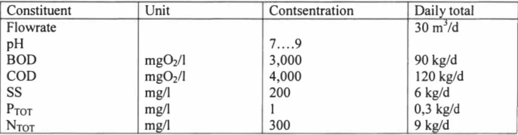
2 BASIC DATA AND TERMS OF REFERENCE FOR DESIGN Table I Data ofleachatesfrom disposal area
Constituent Unit Contsentration Daily total
Flowrate 30 m3/d pH 7 .... 9 BOD mg(}.i/1 3,000 90 kg/d COD mgO2/l 4,000 120 kg/d
ss
mg/I 200 6 kg/d PrnT mg/I I 0,3 kg/d NrnT mg/I 300 9 kg/dPollution load 90 kg BODid responding to 1,500 population equivalents (PD), 2.1 Requirements on LTP effluent
In compliance with the Estonian legislation [I], an effluent of a landfill with the pollution load less than 2,000 population equivalents, must correspond to the following requirements
KALMAR, SWEDEN, November 25-27, 2003 Table 2 Ejfluent requirements
Constituent Marginal value of Or degree of purification
pollution parameter %
mg/I
8OD1 15 major/equal 90%
COD 125 major/equal 90%
ss
25,0 major/equal 80%PrnT in landfill effluent 2,0 major/equal 60%
NrnT in landfill effluent Not aoolicable Not aoolicable
2.2 Additional requirements
Additional requirements and conditions from the client were:
I. To select for leachates treatment a two-step activated sludge treatment where the first step is an activated sludge treatment in a prefabricated container plant and the second step in an oxidation lagoon.
2. The existing collection lagoon was to be utilised for constructing the oxidation lagoon.
3. Total cost of the tum key project had to be less than 1 million EEK (64,000 EUR)
4. For pumping stations, the existing pumping stations were to be utilised ( except for the new underground pumping station, which pumps the partly treated leachates into the oxidation lagoon)
5. No expenditures and efforts were to be made to design and construct a nitrogen removal system.
6. The landfill is situated in a relatively cold climate zone. In the wintertime, the temperature of the leachates remains between +4 to +7e°C for a long period. For technical calculations, the lowest air temperature was recommended
-35°C.
3 TECHNICAL SOLUTION
From the existing wastewater pumping station, sewage pumps pump landfill leachates into a prefabricated container plant for an activated sludge treatment. An electromagnetic flowmeter MAGFLO® has been installed on the inlet pipe. For the optimisation of N:P ratio, a dosing pump adds Ortho Phosphoric Acid (1 I contains 273 g P) to the container inlet.
The volume of the aeration tank (AT) is 70 m3 • 02 concentration is retained at 0,8 -1,5 mg/I. On the bottom of AT, there are 42 PU diffusers AFD270 (from Stamford Scientific International, USA).
KALMAR ECO-TECH'03 Bioremcdiation and Leachate Treatment
KALMAR, SWEDEN, November 25-27, 2003
A dry installation pump pumps the return sludge back to AT. The same pump pumps excess sludge to an excess sludge container. The excess sludge container is periodically depleted to disposal area.
From AT the partly treated leachates flows to the underground pumping station which pumps the partly treated leachates into the oxidation lagoon.
The existing collection tank were separated by bulkhead into two parts: oxidation lagoon and anoxic lagoon.
On the bottom of the oxidation lagoon there are 128 pcs Airflex PU tube diffusers 62*610 mm.
From the oxidation lagoon the mixed liquid flows into the anoxic lagoon and from the anoxic lagoon trough decanting overflow into a recipient stream.
The pressure pipeline from the pumping station to the oxidation lagoon inlet is supplied with electrical heating. Decanting overflow of the anoxic lagoon is also supplied with electrical heating.
In case of necessity, it is also possible to lead the treated effluent of anoxic tank for diluting raw leachates from the disposal site as a respective system has been built.
so/·
7,5 7,5
KALMAR, SWEDEN, November 25-27, 2003
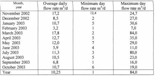
4 ACTUAL FLOWRATE AND TREATMENT EFFICIENCY
Plant started under operation in October 2002.
Table 3 Actual flow rate ofleachates
Month, Overage daily Minimum day Maximum day
year flow rate m3/d flow rate m3 /d flow rate m3 /d
November 2002 17,2 12,4 24,7 December 2002 8,5 2 27,0 January 2003 10,7 5 30,6 February 2003 3,2 I 7,0 March 2003 17,8 2 84,0 April 2003 12,7 5 35,0 May 2003 12,0 7 29,0 June 2003 5,9 4 11,0 July 2003 11,3 3 80,0 August 2003 10,5 5 23,0 September 2003 6,8 I 16,0 October 2003 10,7 6 19,0 Year 10,25 I 84,0
4.1 Constituent concentrations of leachates from disposal area
Table 4. Leachates constituent concentrations
BOD1 COD pH Prnr Nrnr NO3
-mg/I mg/I mgN/1 mg/I mg/I
ss
mgO2/I mgOi/1 �t November 371 111 8,0 3,8 236,2 708 December 3,576 8,130 7, 19 1,64 4 10,8 205 253 March 1,650 2,700 7,0 0,76 17 1 8,0 210 2,000 6,000 0,05 O,o3 May June 5,300 6,900 7,05 7,25 2,7 1,8 5 18 397 51 2,645 4,240 7,56 2,4 13.August 445 7,5 2 1,4 2,385 4,340 7,52 1,4 468 1,760 3,900 4 16 I S.August 17.August 19.August 1,530 3,740 7,44 7,48 1, I 1,4 434 1,850 3,475 7,48 482 26.August 1,08 5 1,550 3,157 7,49 1,5 436 1,700 2,900 7,55 2,0 5 02.September I I .September 400 0,05
---�
I
KALMAR ECO-TECH'0J Bioremediation and Leachate Treatment KALMAR, SWEDEN, November 25-27, 2003
9000 8000 +---"J--- 7000 ++---"J---+---"J---+---"J---+---"J---+---"J---++---"J---++---"J---+---"J---+---"J---+---"J---+---"J---+---"J---+---"J---+---"J---+---"J---+---"J---+---"J---+---"J---+---"J---+---"J---+---"J---+---"J---+---"J---+---"J---+---"J---+---"J---+---"J---+---"J---
]>
6000 +---+----l�---1F'----\---§
3000 +--1---.f--''<---1:l---+---�---_..,,,--u 2000 1t1 '-- -�-;;;;;;---+---- ---':,,,,.,._,.:::::::::::::::.:::::::::��► 1000 +---- ---0Ut::::�::::::k:����=���=��=�
·� 5000 � 4000+--J---:---
_j
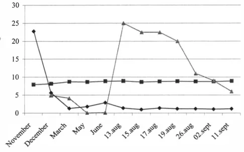
r-,1---,1--\-��!:::::,,,--==-=---+- BOD7 --- COD -.- Ntot Figure 2, BOD?, COD and NrnT dependence of date in inlet
9�--- -
8+---.---1L___=:::::-==�---��:::r��t=!::�'=��
E 6+---1---+---+- ---C 5+---+---+---+---.---0·�
4+-�---+- ----+---.-��--+---C (,) <I) 3 +-�-.---+---�-+---1---+---+--Cu
0 2 +�....;�, ... � .... -0 +--�-�-�lr-,--,,i-�-�-����-�-�---.11� -+- Ptot --- pH -.- NO3�
so/·
99
8,7
98
8,9 75
KALMAR, SWEDEN, November 25-27, 2003 4.2 Efluent constituent concentrations
Table 5. Effluent constituent concentrations
BOD1 COD pH PrnT NrnT NO3.
ss
onstituent mgOi/1 mgO2/l mg/I mg/I mgN/1 mg/I mg/I 42 19,8 1 1 1 7,93 22,74 165,8 November December 58,5 370 8, 15 5,62 4,9 295 60 March 60 500 1,3 145 4, 1 174 50 420 8,65 1,8 13 1 <0,02 May June 62 430 8,85 2,9 1 15 0, 1 70 13.August 55 567 8,9 1 1,4 84 25 IS.August 5 1 535 8,65 1,0 105 22,5 17.August 77 547 8,79 1,4 102 22,5 19.August 36 556 8,85 1,2 105 20 26.August 30 446 8,76 1,2 147 1 1 02.eSeptember 75 474 8,78 I, 1 130 9 I I.September 52 450 1,2 6,0 5 1 600 500 400 C: 0
-�
300 C: 200 C: 0 100 0-+- BOD? --- COD -.- Ntot Figure 4. BOD7, COD and NrnT dependence of date in effluent
�
97,5
KALMAR ECO-TECH'03 Bioremediation and Leachate Treatment KALMAR, SWEDEN, November 25-27, 2003
E C:
·�
C: C: 30 25 20 15 JO -+-Ptot ---pH -.-NO3 Figure 5. PrnT, pH and NO3"dependence of date in effluent.5 BOD, COD AND N EFFICIENCY
Table 6. Treatment efficiency
BOD1 COD NrnT % % % onstituent November 94,7
-
29,8 98,4 75,9 96,4 December 95,4 8 1,5 March 15,2 67 77,8 May June 98,8 93,093,8 August 97,5 86,5 September 96,0 84,7 Averlll!e 97,0 90,1 75,8 75,4 60.0120
100
� 80
1
---��---::::::;,;:::::=====::;:::==�
;:,-..§
CJffi
60
-+----�---40
+---F---\----+---+- BOD7 --- COD
--:it:-Ntot
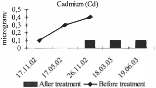
Figure 6. BOD7, COD and NroT treatment efficiency dependence of month 5.1 Concentrations of heavy metals in Viiiitsa Landfill leachates and effluent
Table 7. Concentrations of heavy metals in Viiiitsa Prugila leachates and effluent
Before plant Before
Constituent Unit operation treatment After treatment plant Standard 17.0e1.02 17.05.02 26.11.02 26.11.02 18.03.03 19.06.03
Cadmiwn(Cd) µg/1 <0,1 0,3 0,4 0.1 <0,1 <0,1 0,2 Chromiwn(Cr) mg/I 0,Q35 0,144 0,099 0,016 0,026 0,026 0,5 Copper (Cu) mg/I <0,04 0,047 <0,04 <0,04 <0,05 <0,04 2
Mercury(Hg) µg/1 <0,05 <0,05 0,1 <0,05 0,022 <0,05 0,05
Nickel (Ni) mg/I 0,015 0,148 0,096 0,016 0,006 0,024 I µad (Pb) mg/I 0,01 0,01 0,009 0,004 0,022 0,001 0,5
IZinc (Zn) mg/I 0,03 0,077 0,121 0,012 0,04 0,01 2
NB Storage of wastes started in November of 2000. Leachates treatment started in October of 2002.
� '\,�·
�
"'
�
"'
�
"'
�
"'
,�
�·
0,3 Sb ��-+-1 �----+-I ��-<I 1 0 --l---+-1 ---1 5 0,0 !c· ... ,. ""' (?· KALMAR ECO-TECH'03 Bioremediation and Leachate Treatment KALMAR, SWEDEN, November 25-27, 2003Cadmium (Cd) 0,5 §0,4 § 0,2 0,1 -i§ / ' • - -1 Figure 7.1. Cadmium (Cd) Chromium (Cr) 2 0. 0,1 5
I
0 -4--,E
__..,___ 1,__.--.______.1�•---+-1 �-�-< 0,1- After treat:Irent -+- Befure treat:Irent
Figure 7.2. Chromium (Cr) Copper (Cu)
��:
0 06�t
:::a
II
I
,
'·"�
v"'
"'",,·
- After treat:Irent -+- Befure treat:Irent
,,·
..."'" a_� ._o."!> Figure 7.3. Copper (Cu)
�
-�
�e
0 0,06
i-KALMAR, SWEDEN, November 25-27, 2003
Mercury (Hg) _ E E 0,12
I
0 1 0,08 0,04 0 0, .e_e✓-I
I
6 -+---�l----+-1 -'-L-.1___.•-..--1-1-"-L----11- After treatirent -+- Befure treatJrent
Figure 7.4. Mercury (Hg)
L::
0,2 Nickel (N0 0,15i
0,1 E 0,05 0 -l----�-+---+---'-"---f---"--l---l L----11Figure 7.5 Nickel (Ni)
ad b) Lee (P
\��;
t
I
'§ii 0,015 E 0,01 ••--.. •--_.♦ 0,005 0 +----+---+-�-�-+-1 �--+1 �--.__,�
"'
b·°'
r;;;i'
- After treatJrent -+- Befure treatJrent
KALMAR ECO-TECH'03 Bioremediation and Leachate Treatment KALMAR, SWEDEN, November 25-27, 2003
Zim(Zn) 0, 15 �0,1
t
60,
os/
/ O+----+---�lf-"--�r1�•-�r1�---, Figure 7.7. Zinc (Zn) 6 REFERENCES[1] Vabariigi Valitsuse 31.juuli 2001 a. miilirus nr 269 "Heitvee veekogusse voi pinnasesse juhtimise kord" R TI 200 I, 69, 424