Technical Note
Rock Mechanics –
Evolution of fracture transmissivity within different
scenarios in SR-Site – Main Review Phase
2013:37
Author: Ki-Bok Min
Jaewon Lee Ove Stephansson
SSM perspektiv
BakgrundStrålsäkerhetsmyndigheten (SSM) granskar Svensk Kärnbränslehantering AB:s
(SKB) ansökningar enligt lagen (1984:3) om kärnteknisk verksamhet om
uppfö-rande, innehav och drift av ett slutförvar för använt kärnbränsle och även
inkaps-lingsanläggning. Som en del i granskningen ger SSM konsulter uppdrag för att
inhämta information och göra expertbedömningar i avgränsade frågor. I SSM:s
Technical Note-serie rapporteras resultaten från dessa konsultuppdrag.
Syfte
Det övergripande syftet med projektet är att ta fram synpunkter på SKB:s
säkerhets-analys SR-Site för den långsiktiga strålsäkerheten hos det planerade slutförvaret i
Forsmark. Syftet med detta projekt är att undersöka och bedöma möjliga
variatio-ner av bergsprickornas transmissivitet (genomströmnings-förmåga) som en följd av
de belastningar som kommer att verka på slutförvaret. Projektet utvärderar SKB:s
antaganden gällande bergsprickornas transmissivitet, vilka ligger till grund för de
belastningsscenarier som SKB har föreslagit för SR-Site och i sin tillståndsansökan
om att få bygga ett slutförvar för använt kärnbränsle i Forsmark.
Författarnas sammanfattning
Detta granskningsuppdrag består av en litteraturstudie samt oberoende
modelle-ring för att bedöma betydelsen av transmissivitetsförändmodelle-ringar hos bergsprickor,
driven av skjuvbelastning på grund av förhållandena i SKB:s termiska, glaciala och
jordbävning belastningsscenarier för ett KBS-3-förvar vid Forsmark.
Rapportens inledande del består av en genomgång av SKB:s laboratorieexperiment
på skjuvinducerad sprickutvidgning samt en litteratursammanställning av
kun-skapsläget gällande bergsprickors transmissiviteten vid normal- och
skjuvbelast-ning. SKB:s laboratorieförsök på bergsprickor från Forsmark visar att dilatationen
(ökad öppning) av sprickor i samband med skjuvbelastning är betydande. I likhet
med SKB:s arbete visar den internationella litteraturen att redan små
skjuvdefor-mationer av bergsprickor under normalspänningar upp till 20 MPa leder till en
bestående ökningar i transmissiviteten och att denna ökning kan ha betydelse för
radionuklidtransporten under den termiska och långsiktiga utvecklingen av
slut-förvaret.
Den andra delen av rapporten beskriver resultaten från egna modelleringar av
transmissivitetsförändringar pga. termiskt inducerad skjuvning av sprickor i
slut-förvaret. Generiska sprickor, verkliga spricknät från Forsmark samt stora
deforma-tionszoner på långt avstånd från slutförvaret har studerats med en kombination
av diskreta elementmodeller med beräkningskoden UDEC och diskreta
sprick-nätverksmodeller (DFN-modeller). Resultaten visar bl a att transmissiviteten kan
öka upp till två tiopotenser för en spricka med en initiell spricköppning på 30 μm
och att detta kan ske på ett avstånd av mer än 10 m från en deponeringstunnel.
Både transmissivitetens magnitud och avstånd från en deponeringstunnel till en
spricka där ökningen kan ske är större än vad SKB anger. Den ökade
transmissivite-ten till följd av skjuvningen är icke-reversibel vilket innebär att den ökade
genom-strömningen till följd av belastningen under uppvärmningsfasen kvarstår under
avsvalnandet och senare. Denna permanenta ändring kan påverka buffertens och
återfyllningens egenskaper och inverka på radionuklidtransporten och den
långsik-tiga säkerheten hos slutförvaret.
Den tredje och fjärde delen av rapporten behandlar transmissivitetförändring till
följd av en glaciationscykel samt jordskalv från någon av de närliggande större
deformationszonerna i Forsmarksområdet. Undersökningarna gjordes med samma
DFN modeller som användes vid modelleringen av termiskt inducerad skjuvning
av sprickor. Modelleringsresultaten visar att inverkan av belastningen från en
inlandsis är mestadel elastisk och fullt reversibel. Inverkan av ett jordskalv
simu-lerades genom syntetiska markrörelser på modeller med korta sprickor på 5, 10
och 15 m, vilket visar att en irreversibel ökning av spricköppning på upp till 20
μm sker när spänningsförhållandet är nära sprickans skjuvhållfasthet. Dock, för
DFN modeller i närområdet av transporttunnel och deponeringshål visar
model-leringsresultaten att en irreversibel spricköppning inte förekommer. Detta
uteslu-ter inte att enskilda sprickor med ogynnsam orienuteslu-tering i förhållande till rådande
spänningstillstånd i berget kan genomgå irreversibel dilatation på grund av ett
jordskalv. Det finns behov av ytterligare modellering av jordskalv för att studera
effekten på transmissiviteten för olika DFN modeller.
Projekt information
Kontaktperson SSM: Flavio Lanaro
Diarienummer ramavtal: SSM2011-3631
Diarienummer avrop: SSM2013-2462-6
Aktivitetsnummer: 3030012-4062
SSM perspective
BackgroundThe Swedish Radiation Safety Authority (SSM) reviews the Swedish
Nuclear Fuel Company’s (SKB) applications under the Act on Nuclear
Activities (SFS 1984:3) for the construction and operation of a
reposi-tory for spent nuclear fuel and for an encapsulation facility. As part of
the review, SSM commissions consultants to carry out work in order to
obtain information and provide expert opinion on specific issues. The
results from the consultants’ tasks are reported in SSM’s Technical Note
series.
Objective
The general objective of the project is to provide review comments on
SKB’s postclosure safety analysis, SR-Site, for the proposed repository
at Forsmark. The objective was to evaluate the range of possible
varia-tion of fracture transmissivity of natural fractures at Forsmark due to the
loading configurations covered by SKB’s scenarios. The argumentations
provided by SKB for supporting the assumptions about fracture
trans-missivity in SR-Site should be evaluated from the viewpoints of
plausibil-ity and coverage of all the possible loading cases.
Summary by the authors
The current review assignment consists of a literature review and
inde-pendent modeling for assessing the importance of fracture
transmis-sivity change especially driven by shear loading due to SKB’s thermal,
glacial and earthquake loading scenarios for the KBS-3 repository at
Forsmark.
In the first part of the report, SKB’s laboratory experiments on shear
fracture dilation and extensive literature review on shear fracture
dila-tion in-situ and in laboratory under moderate normal stress show that
dilation can become important even under moderate normal stress of
about 20 MPa. Importantly, the increase of transmissivity induced by
shear dilation would not recover to its initial state after cooling of the
repository because the process occurs at shear failure, as demonstrated
by the experiments in the literature. This permanent change of
transmis-sivity can impact on the safety assessment of the repository for issues
related to buffer resaturation time and radionuclide transport.
In the second part of the report, a modeling study focuses on the
trans-missivity change from thermally-induced shearing of fracture around
repository on three types of geometries with a single fracture, realistic
Discrete Fracture Network (DFN) models for Forsmark, and a far-field
model with large scale deformation zones at the Forsmark site. The
thermal shearing analysis was conducted by means of a discrete element
method code, UDEC. DFNs were independently generated based on the
fracture data provided by SKB. It was shown that transmissivity increase
can be up to 2 orders of magnitude for an initial fracture aperture of 30
μm. These large transmissivity changes can occur around 10 m from the
deposition tunnel. This indicates that significant changes are possible
anywhere between adjacent deposition tunnels because dilation occurs
and shear stresses can exceed the frictional strength of the fractures and
deformation zones. Furthermore, because the frictional strength of some
fractures was exceeded, irreversible shear dilation occurs, which does not
recover to its initial state in the models after cooling of the repository.
The magnitude and spatial extent of the transmissivity change is greater
than the investigations reported by SKB. The significance and limitation
of the modeling was discussed in view of parameters from fracture
char-acterization, two-dimensionality of the used DFNs and numerical code.
In the far-field model, the gently dipping deformation zones were most
prone to shear dilation under thermal loading.
The third and fourth part of the report concern the effect of glacial and
earthquake loading on transmissivity change. Investigations were made
on the same DFN models used for the thermal study. The effect of
glacia-tion on fracture transmissivity change was negligible due to the fact that
glacial loading were increased in an almost isotropic manner, which does
not promote shear slip. Furthermore, induced shear displacements in
the models recovered after the retreat of the ice, which indicates that
shear behavior of the fractures during a glacial cycle is mainly elastic.
Earthquake modeling was conducted by applying synthetically generated
ground motion to the models surrounded by viscous boundaries.
Earth-quake loading on a conceptual model containing a single fracture with
size of 5, 10 and 15 m shows that there can be up to 20 μm of permanent
aperture increase when the stress condition is close to shear failure. This
result shows that the effect of an earthquake needs to be investigated,
not only in terms of canister integrity, but also in terms of fracture
trans-missivity change. Earthquake modeling on DFN models, however, showed
that actual shear dilation is negligible due to the fact that fracture
orientation is not favorable to shearing. Further systematic investigation
may be required on the effect of various DFN statistics and earthquake
conditions.
Project information
Contact person SSM: Flavio Lanaro
Reference: SSM2013-2462-6
2013:37
Author: Ki-Bok Min (1), Jaewon Lee (1), Ove Stephansson (2) (1) Seoul National University, Seoul, Korea
(2) Stephansson Rock Consulting, Berlin, Germany
Rock Mechanics –
Evolution of fracture transmissivity within different
scenarios in SR-Site – Main Review Phase
This report was commissioned by the Swedish Radiation Safety Authority
(SSM). The conclusions and viewpoints presented in the report are those
of the author(s) and do not necessarily coincide with those of SSM.
Contents
1. Introduction ... 3
1.1. Background ... 3
1.2. Scope of the current assignment ... 6
2. Literature and laboratory studies on transmissivity evolution ... 9
2.1. SKB’s presentation ... 9
2.1.1. Literature review conducted by SKB ... 9
2.1.2. Transmissivity change due to normal closure ... 11
2.1.3. Transmissivity change due to shear stress ... 12
2.1.4. Measured dilation on samples from Forsmark ... 13
2.2. Motivation of the assessment on SKB’s literature and laboratory studies ... 15
2.2.1. Shear dilation behavior ... 15
2.2.2. Irreversibility of shear dilation ... 20
2.3. The Consultants’ assessment on SKB’s literature and laboratory studies ... 20
3. Modelling of the evolution of fracture transmissivity during the thermal phase of the repository ... 21
3.1. SKB’s presentation ... 21
3.1.1. Transmissivity changes due to normal stress ... 21
3.1.2. Transmissivity changes due to shear stress ... 22
3.1.3. Spatial extent of transmissivity changes ... 23
3.2. Motivation of the assessment on the evolution of fracture transmissivity during the thermal phase based on independent TM modelling ... 24
3.2.1. Data and geometry for the independent TM modelling ... 24
3.2.2. Thermal loading ... 28
3.2.3. Conceptual model of fracture transmissivity evolution during the thermal phase ... 32
3.2.4. Discrete Fracture Networks (DFN) for the independent TM modelling ... 37
3.2.5. Independent TM modelling of the near-field with DFN for fracture transmissivity evolution during the thermal phase ... 42
3.2.5.1. NE section... 42
3.2.5.2. NW section ... 48
3.2.5.3. HZ section ... 51
3.2.6. Irreversibility of shear dilation in the independent TM modelling ... 54
3.2.7. Independent analysis of the far-field for fracture shear slip evolution during the thermal phase ... 55
3.3. The Consultants’ assessment on the evolution of fracture transmissivity during the thermal phase based on independent TM modelling ... 58
4. Modelling of the evolution of fracture transmissivity during the glacial phase of the repository ... 61
4.1. SKB’s presentation ... 61
4.1.1. Transmissivity change due to normal stress ... 62
4.1.2. Transmissivity change due to shear stress ... 63
4.2. Motivation of the assessment on the evolution of transmissivity during the glacial phase based on independent modelling ... 64
4.2.2. Glacial loading ... 64
4.2.3. Conceptual model of fracture transmissivity evolution during the glacial phase ... 66
4.2.4. Independent modelling of the near-field with DFN for fracture transmissivity evolution during the glacial phase ... 68
4.2.4.1. NE section... 68
4.2.4.2. NW section ... 72
4.3. The Consultants’ assessment on the evolution of transmissivity during the glacial phase based on independent TM modelling ... 77
5. Modelling of the evolution of fracture transmissivity during an earthquake close to the repository ... 79
5.1. SKB’s presentation ... 79
5.1.1. SKB’s analysis of effect of an earthquake on transmissivity change ... 79
5.1.2. Effect of earthquake on fracture shear slip ... 80
5.2. Motivation of the assessment on evolution of transmissivity by independent modelling of an earthquake ... 81
5.2.1. Data and geometry for earthquake loading phase ... 82
5.2.2. Earthquake loading ... 83
5.2.3. Conceptual model of shear displacement evolution during an earthquake ... 86
5.2.4. Independent modelling of the near-field and DFN for shear displacement and transmissivity evolution during an earthquake . 94 5.3. The Consultants’ assessment on the evolution of fracture transmissivity during an earthquake close to the repository ... 97
6. The Consultants’ overall assessment on the evolution of fracture transmissivity ... 99
7. Acknowledgements ... 103
8. References ... 105
APPENDIX 1 Coverage of SKB reports ... 111
APPENDIX 2 Description of the Discrete Fracture Network used in this study ... 113
APPENDIX 3 Thermo-mechanical modelling – Supplementary results 133 APPENDIX 4 Earthquake modelling – Supplementary results ... 139
1. Introduction
This assignment is part of Main Review Phase conducted by the Swedish Radiation Safety Authority (SSM) on the SR-Site safety assessment of the final disposal of spent nuclear fuel at the Forsmark in the application for construction license submitted by the Swedish Nuclear Fuel and Waste Management Company (SKB). This assignment concerns the evaluation of ranges of possible variation of fracture transmissivity of natural faults and fractures at Forsmark due to the loading configurations covered by SKB’s scenarios. The argumentations provided by SKB for supporting the assumptions about fracture transmissivity in SR-Site are evaluated from a point of view of plausibility and coverage of all the possible loading cases. Furthermore, independent analyses of the hydro-mechanical behavior of rock fractures are carried out, presented and discussed. Cases with explicit realizations of the Discrete Fracture Network models (DFN) are evaluated to infer the possible ranges of variation of transmissivity for the different fracture sets occurring at Forsmark. Relevant realizations of the DFN models used for the independent modelling were provided by SSM in agreement with other external experts in the field of fracture network description and simulation (see Appendix 2).
The evaluations of possible transmissivity ranges from the provided DFN model are related to the hydrogeological models used for determination of the groundwater flow into the deposition holes. The Authors have also investigated the loading scenarios in relation to their effects on fracture transmissivity with the purpose of highlighting possible omissions by SKB. In conjunction with the hydro-mechanical analyses, normal and shear displacements on rock fractures in the DFN realizations are evaluated for different scenarios presented in SR-Site, in particular to evaluate the cumulative evolution of fracture transmissivity resulting from the thermal, glacial and earthquake scenarios. The magnitude and regional extent of
transmissivity change investigated by SKB have been evaluated and compared with the results by current independent study in view of safety assessment of geological repository.
An error in the DFN realizations that were input to an earlier version of this report was discovered on March 7, 2014. The error was corrected and new modelling simulations of the evolution of fracture transmissivity were carried out as reported here.
1.1. Background
Several studies have shown that shear displacement and dilation of fractures can be sources of mechanical instability and significant fluid pathways in fractured rock. The thermal stress generated from heat-generating spent nuclear fuel and nuclear waste is in the order of up to 20 MPa and this can alter the stress state around a repository (Figure 1a), generate slip along existing fractures and induce changes of transmissivity. While the effect of the excavation is expected to be produced in the near-field, which means within a few times of the equivalent diameter of the repository tunnel, the influence of thermal stresses will reach mid- and far-field, which can be a few hundred meters from the peripheries of a repository. A field
investigation by Barton et al. (1995) supports the statement that critically-stressed fractures are the ones carrying a major portion of the fluid flow in the rock mass. A similar finding was numerically demonstrated by Min et al. (2004). In a deep geological repository, thermal stresses are generated due to the confined nature of the rock mass at depth and they can be a source of shear slip and dilation of faults and fractures in the repository area (Min et al., 2013). Results from the study by Min et al. (2013) shows the thermal stress evolution, the state of stress after 100 years of disposal plotted as Mohr Circle and the shear slip zone due to thermal stresses based on fracture data from Forsmark (Figure 1). It was also concluded that “thermo-shearing”, which is the phenomenon of shear displacement and dilation of faults and fractures due to thermal loading, is an important mechanism to be studied to ensure the safe disposal of nuclear waste in deep geological repositories (Min et al., 2013). The transmissivity change associated with thermo-shearing is also expected to affect the pattern of fluid flow underground and is especially important since increased transmissivity due to shear dilation may not be reversible during the cooling phase of the repository. The candidate site at Forsmark proposed by SKB indicates a high stress ratio (i.e. the ratio of major principal stress to minor principal stress) and this implies that many fractures in the site area are critically or nearly-critically stressed under the current stress state according to SKB’s site investigations (Glamheden et al., 2007). This means that even a slight change of stress can trigger a shear slip. Furthermore, the sparsely fractured rock at Forsmark will have relatively high elastic modulus and this will induce higher thermal stresses. It is noted that thermal loading of the repository occur in the far-field at relatively early time after closure (about 1,000 years) and has a direct effect on the radionuclide transport and overall performance of the repository.
Ice loading due to a glaciation and occurrence of earthquakes also inevitably alters the state of stress in the rock mass resulting in the shear slip of fractures. The analysis of the effect of earthquakes on the transmissivity change is necessary given that most of previous earthquake analyses focus on canister integrity resulting from fracture shear displacement (e.g. Fälth et al., 2010). Although small earthquakes may not affect the large-scale integrity of the repository, they can possibly induce notable transmissivity changes by shear slip. Therefore, the cumulative effect of thermal, earthquake and glacial loading deserves a systematic investigation based on realistic DFN models.
In summary, the change of transmissivity will have an impact on the performance assessment of a deep geological repository, and there is not yet in SKB
documentation a complete quantitative analysis related to the transmissivity change induced by the thermal, glacial and earthquake scenarios.
(a)
(b)
Initial state
After 100 years
(c)
Figure 1. The geological repository performance for shear slip potential. (a) evolution of notable compressive stresses at selected points at a repository level of about 400 m, (b) initial stress and stress after 100 years, and (c) shear slip zone shown in stereonet at an initial state and after 100 years (Min et al., 2013).
1.2. Scope of the current assignment
This study brings up technical issues that were not covered in sufficient detail by SKB for the construction license application of the final repository for spent nuclear fuel at Forsmark. The following tasks related to evolution of fracture transmissivity within different scenarios in SR-Site were performed for this study:
Task 1. Literature review on the shear dilation of fractures in laboratory and in situ under moderate normal stress (5 to 25 MPa).
Task 2. Transmissivity evolution for the thermal phase of the repository: 1. Transmissivity change in a conceptual model
2. Transmissivity change in the near-field DFN model from Forsmark 3. Transmissivity change in far-field model from Forsmark
Task 3. Transmissivity evolution for the glacial phase of the repository: 1. Transmissivity change in a conceptual model
2. Transmissivity change in the near-field DFN model from Forsmark Task 4. Transmissivity evolution for an earthquake occurring close to the
repository:
1. Transmissivity change in a conceptual model
2. Transmissivity change in the near-field DFN model from Forsmark. Task 1 undertakes a literature review of the existing knowledge about shear dilation in a fracture under moderate normal stress. Although SKB’s license application did conduct a literature review and cited several important studies (Fransson, 2009), there is a significant underestimation of the shear dilation due to thermal stress. Task 2 focuses on the transmissivity change due to thermally-induced shearing (thermo-shearing) of fractures around the repository. This task was conducted on three types of geometries, namely: (i) a conceptual model with a single fracture, (ii) a realistic DFN model and (iii) a far-field model with large scale deformation zones at the Forsmark site.
Task 3 focuses on transmissivity change from glacial loading around the repository. A conceptual model containing a single fracture was tested first. Main study was conducted on a realistic DFN model and was meant to reveal the effect of glaciation superimposed on the thermally induced change of transmissivity.
Task 4 deals with the effect of an earthquake on the transmissivity change around the repository. This task starts with a simple conceptual model containing a single fracture followed by applications on more realistic DFN model. The earthquake loading was applied at a few selected times on the repository model subjected to thermal and glacial loading.
The analyses in the current study were mainly conducted by applying the two-dimensional Discrete Element Method (DEM) code UDEC (Itasca, 2014). The study was conducted with an explicit consideration of fractures to overcome the limitation in SKB’s work, which only used an elastic thermo-mechanical calculation and neglected shear dilation. While Min and Stephansson (2009) used a combination of
directly uses the DEM code for coupled thermo-mechanical analyses. This approach gives a more realistic estimation of thermal shearing of rock fractures.
Key mechanisms focused on in this assignment include transmissivity increase due to shearing and irreversibility of displacements at shear failure of rock fractures. For dilated fractures under high normal stress, a permanent increase of transmissivity is anticipated contrary to the usual expectation that transmissivity will recovery after unloading. Figure 2 shows an illustration of the topics covered in this assignment.
2. Literature and laboratory studies on
transmissivity evolution
2.1. SKB’s presentation
2.1.1. Literature review conducted by SKB
Fransson (2009) reviewed previous works on the relationship between normal stress or normal stiffness and hydraulic aperture. Particular focus was given to experiences from field experiments. Those fields are listed below:
Coaraze Laboratory, France (Cappa et al., 2006; Guglielmi et al., 2008a, b) Röda Sten Rock Laboratory, Sweden (Alm, 1999)
Rock Mechanics Laboratory of Luleå University of Technology, Sweden (Rutqvist et al., 1998)
Underground Research Laboratory (URL), Canada (Martin et al., 1990) Äspö Hard Rock Laboratory, Sweden (Rutqvist et al., 1998)
Laxemar (HLX), Simpevarp (HSH), Ävrö (HAV), Äspö (HAS) (Rhén et al., 2008).
Figure 3 shows the compilation of equivalent hydraulic aperture and normal stiffness values by Fransson (2009).
Detailed field data on shear deformation and transmissivity were not found. However, the relationship between shear stress and deformation were derived by previous studies (Bandis et al., 1983; Barton et al., 1985; Olsson, 1998; Olsson and Barton, 2001). During fracture shear movements the aperture will change due to dilation. Especially transmissivity increases considerably for shear displacements exceeding a couple of millimeters, and transmissivity increase appears to be sensitive to normal load variations (Figure 4). SKB argues that most of the previous studies were conducted under low normal stresses. It is found that higher stress suppressed the joint dilation thus limiting the increase of hydraulic aperture. Gouge production would also tend to reduce transmissivity. Consequently, SKB assumed that transmissivity increases caused by shear dilation taking place under effective normal stresses higher than around 6 to 7 MPa were sufficiently small to be ignored.
Figure 3. A compilation of equivalent hydraulic aperture and normal stiffness values (Fransson, 2009). Note that the original figure is slightly modified here to improve the resolution.
Figure 4. Measured transmissivity of fractures of Ävrö granite as a function of shear displacement. The hydro-mechanical shear tests were conducted under different values of normal stiffness (Olsson, 1998).
On the other hand, Esaki et al. (1999) conducted direct shear tests under normal stress of 1, 5, 10 and 20 MPa using granite replicas. The measured hydraulic conductivity, which varied in proportion to the square of aperture, increased almost 2 orders of magnitude with shear displacement of 20 mm and normal stress of 20 MPa. The observed shear dilation was 2.9 mm and 1.0 mm under normal stress of 1 MPa and 20 MPa, respectively. These results show that change of shear dilation and hydraulic conductivity can be significant even under high normal stress. Note
2.1.2. Transmissivity change due to normal closure
An exponential expression (Liu et al., 2003) was used in the SR-Can assessment of thermo-mechanical and hydraulic rock processes (THM) (Hökmark et al., 2006).The exponential expression for aperture (e) versus normal stress was given by:
max
exp(
)
r n
e e e
Eq. (2.1)where er is the residual aperture, σn the effective normal stress whereas emax and α are
model parameters. The transmissivity T of individual fractures is a function of hydraulic aperture e given as:
3
12
g
T
e
Eq. (2.2)where g is the gravitational acceleration, 𝜌 is the fluid density and 𝜇 is the dynamic viscosity of the fluid.
While SKB acknowledged the distinction between mechanical and hydraulic apertures, the mechanical aperture was used for the investigations because of the difficulty in obtaining accurate hydraulic apertures determinations in hard rock. This is considered to be a conservative and reasonable approach given the nature of the problem. Once stress-aperture relations are established, the relative transmissivity is given by the following expression using the cubic flow law:
30 0
/
/
T T
e e
Eq. (2.3)where T0 and e0 are the initial transmissivity and aperture, respectively.
SKB choses two normal stress-transmissivity models (denoted as Models A and B) to estimate normal stress-induced transmissivity changes. In both models, the residual aperture at high normal stress was based on reported transmissivity values for fractures below 400 m depth in the fracture domain FFM01 at Forsmark (Follin et al., 2007). Model A can be considered a “worst case” based on lower bound of the normal stiffness estimates of the fracture and is therefore very sensitive to normal stress variations. Model B is based on average fracture normal stiffness estimates and is less sensitive to variations in normal stress. Figure 5 shows the normal stress versus aperture relations and the parameter values for each stress-transmissivity model as indicated in Hökmark et al. (2010).
Figure 5. Relative transmissivity and hydraulic aperture versus effective normal stress used by SKB (Hökmark et al., 2010).
2.1.3. Transmissivity change due to shear stress
The dilation angle of a fracture can be calculated by means of Eq. (2.4) as suggested by Barton and Choubey (1977):
log(
)
nJCS
JRC
Eq. (2.4)where ϕ is dilation angle, JRC is Joint Roughness Constant, JCS is Joint wall Compression Strength, and σn is effective normal stress. The dilation angle can be
reduced by half as necessary.
The actual change of the aperture induced by shearing can only be calculated from an elasto-plastic analysis with an explicit representation of the fractures after shear failure. Instead of conducting this type of analyses, SKB only estimated the maximum shear displacement (Δu) at given monitoring lines based on the stress drop 𝜏𝑑𝑟𝑜𝑝 defined as the difference between the shear stress acting on the fracture plane and the strength of the fracture (Hökmark et al., 2010):
24
7
dropu
a
G
Eq. (2.5)where G is shear modulus and a is the half fracture length.
It can be noted that there was no estimation by SKB of the transmissivity change due to shear dilation. The rationale for not doing this estimate is summarized as follows (Hökmark et al., 2010):
The stress distribution in real fractures is different than that in the
conceptual model, which makes it difficult to predict the dilation behavior; Dilation behavior under high normal stress regime (> 5 MPa) is sufficiently
small to be ignored;
Gouge production due to asperity damage will reduce the fracture transmissivity.
2.1.4. Measured dilation on samples from Forsmark
SKB did conduct laboratory tests on a number of fracture samples to measure the dilation behavior of rock fractures at Forsmark (Glamheden et al., 2007). Depending on the distance from the deposition tunnel and holes in the repository, normal stress acting on the fractures will vary between less than 5 MPa very close to the openings (less than a few meters), and as much as close to 40 MPa when the fracture plane is perpendicular to the maximum horizontal stress at the repository level.
Figure 6 shows the dilation angle obtained from laboratory tests on a total of 57 fracture specimens taken from different fracture domains and deformation zones at Forsmark. The empirical equation that provides the dilation angles is also reported. The laboratory tests show that the mean dilation angle under normal stress of 5 MPa and 20 MPa are 7.7 ° and 3.2 °, respectively (see Table 1).
The secant dilation angle was determined for a shear deformation between 0.3 mm and 1.3 mm at the 0.5 MPa normal stress level, between 0.5 mm and 1.9 mm at 5 MPa and between 0.7 mm and 2.1 mm at 20 MPa, respectively. Many samples showed dilation angles higher than 10°. These laboratory results on rock samples from Forsmark agreed reasonably well with the existing empirical results (Figure 6b). Dilation angles of 7.7° and 3.2° corresponded to the normal opening at 14% and 6% of the maximum shear displacement, respectively. For example, when there is maximum shear displacement of 27.8 mm, which is expected to occur in the center of a 150 m long fracture (Hökmark, 2010, Figure 6-27), there will be around 3500 μm and 1500 μm shear dilation for 5 MPa and 20 MPa, respectively. These values imply that there will be at least 1 to 2 orders of magnitude increases of the aperture given that the initial aperture is usually less than 100 μm, and accordingly there can be 3 to 6 orders of magnitude changes in transmissivity given the cubic relations shown in Eq. (2.3).
Figure 7b shows the range of fracture shear displacement, dilation and associated relative fracture transmissivity. The maximum shear displacement considered for a fracture is 5000 mm, which is the threshold for canister damage due to earthquake loading in the repository. The larger the fracture size becomes, the greater the magnitude of the shear displacement and dilation. The expected relative transmissivity change for the maximum shear displacement three orders of
magnitude for an initial aperture of 30 μm, and this can become up to five orders of magnitude for a dilation angle 15°. This figure demonstrates the importance of considering fracture shear displacement and dilation for thermo-mechanical, glacial and earthquake loading scenarios.
Obviously, there are issues regarding the size of fractures, the distinction between mechanical and hydraulic apertures and whether or not such dilation will hold throughout the full shear displacement. However, it is important to pay due attention to the measured dilations even under high normal stress as shown in Figure 6.
(a)
(b)
Figure 6. (a) the dilation angle from the laboratory tests on fracture samples taken at Forsmark (Glamheden et al., 2007) and (b) empirical equation for shear dilation for two JRC values (Barton and Choubey, 1977).
Table 1. Dilation angles from direct shear tests on fractures from the fracture domain FFM01 at Forsmark (Glamheden et al., 2007).
Normal load (MPa) Mean (°) Std. dev. (°) Minimum (°) Maximum (°) Uncertainty of mean (%) 0.5 14.6 4.1 7.8 27.1 ±10.2 5 7.7 2.7 2.5 13.7 ±12.8 20 3.2 2.1 0.2 9.6 ±23.9
(a) (b)
Figure 7. Fracture shear displacement, aperture and transmissivity. (a) the relationship between aperture and transmissivity based on Eq. (2.2), (b) estimated fracture aperture and transmissivity change with respect to fracture shear
displacement. Note that initial aperture is assumed to be 30μm in this plot.
2.2. Motivation of the assessment on SKB’s literature
and laboratory studies
2.2.1. Shear dilation behavior
The prediction of the dialtion phenomenon of irregular fractures subjected to direct shear loading has been addressed by numerous researchers. Figure 8 shows the compilation of dilation angle for different normal loads from direct shear tests (Bandis et al., 1981; Barton, 1982; Barton et al., 1985; Wibowo et al., 1994; Lee, 1999; Yeo et al., 1998; Homand et al., 2001; Huang et al., 2002). In Figure 8, the graph for the shear dilation angle at Forsmark is calculated by means of Eq. (2.4) with reduction factor by a half.
Data derived from several types of rock; granite (Barton, 1982; Barton et al., 1985; Lee, 1999), sandstone (Bandis et al., 1981), marble (Lee, 1999), and rock replicas (Homand et al., 2001; Huang et al., 2002; Wibowo, 1994; Yeo et al., 1998). All data except those from Barton et al. (1985) were obtained under low normal stress (less than 6 MPa), and the range of obtained dilation angles was between 0° and 20°.
Figure 8. Compilation of the dilation angle versus normal load from direct shear tests. The solid line shows data from the Forsmark site.
Chen et al. (2000) measured the fracture volume and permeability under different confining pressures and shear displacements to study the effects of confining pressure and shear displacement on fracture aperture and permeability. Figure 9 shows the shear dilation angle as a function of confining pressure for a sample of granite with JRC equal to 9. The experimental results were compared to the dilation angle calculated with previous empirical equations by Barton et al. (1985) and Willis-Richards et al. (1996):
1 9
/
eff dil dil n nref
Eq. (2.6)where
dileffis effective shear dilation angle,
dilis shear dilation angle at zero stress,n
is effective normal stress, and
nref is effective normal stress that gives 90% reduction in the compliant aperture. From Figure 9, it can be seen that sample had about 2.2° shear dilation angle under a confining pressure of 20 MPa, which is similar or lower than the confining stress at Forsmark.Figure 9. Shear dilation angle as a function of confining pressure for sample GO1 (Chen et al., 2000).
Figure 10. Hydraulic conductivity versus shear displacement of artificially created granite fracture at 20 MPa normal stress (Esaki et al., 1999).
Esaki et al. (1999) also showed the increase of hydraulic aperture, and increase of the hydraulic conductivity, versus shear displacement under 20 MPa normal stress from direct shear test (Figure 10), where the conductivity increased by two orders of magnitude. After reversing the movement, the hydraulic aperture did not decrease and return to its initial state, but left a residual aperture. That result means that shear dilation is an irreversible process. In the context of geological repository of nuclear waste, increased hydraulic aperture induced by thermal loading will remain unchanged even after temperature has decreased due to cooling of the canisters. In other words, in the vicinity of the repository, the shearing is not likely to be reversed after elasto-plastic fracture deformation has taken place.
Figure 11. Total flow rates in different directions as a function of shear displacements (Koyama et al., 2006).
Figure 11 shows the test results of total flow rates in a fracture in different directions as a function of the shear displacements (Koyama et al., 2006). In this figure, the flow rate perpendicular to shear was larger than the flow rate parallel to shear. Flow channels newly formed perpendicularly to the shear direction were responsible for this particular behavior. Similar findings were also reported by Yeo et al. (1998) where anisotropy ratio decreased from 0.86 to 0.66 after 2 mm shearing indicating relatively larger flow perpendicularly to the shearing direction (the test was conducted on aperture replica of natural sandstone).
A numerical study conducted by Park and Song (2009) with the DEM code PFC showed that shear dilation is inhibited by large normal stresses. However, that study also showed that shear dilation is still significant enough to be considered.
Figure 12a show the layout of the numerical test used for the numerical analyses. That shear opening due to dilation can be up to 400 m for a shear displacement of 1.6 mm under a normal stress of 15 MPa (Figure 12b). This finding also indicates that the existing empirical equation described by Eq. (2.4) may indeed underestimate actual shear dilation (Figure 12c).
(a)
(b)
(c)
Figure 12. Numerical PFC-DEM simulations of dilation of a single fracture (Park and Song, 2009). (a) single fracture model, (b) shear stress-shear displacement versus normal displacement relationship, and (c) normal stress versus peak dilation angle relations for two different joint roughness coefficients.
2.2.2. Irreversibility of shear dilation
It has been observed that shear dilation can be irreversible, which means that hydraulic aperture would not recover to its initial state when reversing the shear load (Esaki et al., 1999). Due to the behavior of fractures in post-frictional failure, most of the induced shear displacements are not recovered even when the effect of thermal stress becomes negligible after cooling of the repository. We argue here that the irreversible nature of transmissivity change is important because any significant shear-induced transmissivity change can become permanent. Furthermore, total transmissivity can even be enhanced because of normal opening due to reduced normal stress during the thermal phase. A recent study by Min et al. (2013) showed through DEM modelling that the equivalent permeability of a rock block with size 5 m × 5 m actually increased by a factor of two due to contribution from the normal opening after cooling. There are few experimental or in situ observations about irreversibility of shear-induced transmissivity under full cycle of heating and cooling, and therefore further investigations including in situ test should be carried out to study the mechanisms and its extent.
2.3. The Consultants’ assessment on SKB’s literature
and laboratory studies
The Authors have the opinion that SKB underestimates the transmissivity change under shear dilation. In fact, during SSM’s Initial Review Phase, it was found (Min and Stephansson, 2012) that SKB had ignored shear-induced transmissivity changes under moderate normal stress, typically larger than 5 MPa (Hökmark et al., 2010). However, experimental and numerical studies support transmissivity changes of up to two orders of magnitude are expected for normal stress up to 20 MPa (see Esaki et al., 1999). For this reason, the laboratory experiments conducted by SKB
contradicted their own modelling assumptions as presented in Hökmark et al. (2010). In conclusion, although the results of shear dilation tests performed by SKB show that dilation behavior is not sufficiently small to be ignored, the effect of shear dilation was not considered in any of the THM calculations by SKB (e.g. Hökmark et al., 2010).
As presented in the literature, hydraulic aperture can increase due to shear even under high normal stress (Chen et al., 2000; Esaki et al., 1999). Moreover, it has been observed that shear process in the rock fractures can be irreversible, which means that hydraulic aperture would not recover to its initial state when reversing the shear load (Esaki et al., 1999). Finally, it was found that fluid flow perpendicular to shear direction increased more than the flow parallel to shear direction (Koyama et al., 2006), which is not considered by SKB.
The Consultants’ assessment is summarized as follows:
The dilation angle of rock fractures obtained from direct shear tests conducted by SKB was 14.6 °, 7.7 ° and 3.2 ° for normal stress of 0.5 MPa, 5 MPa and 20 MPa, respectively. These results show that shear dilation should be considerable during thermal phase of the repository due to the fact that the normal stress variations at repository level are in the vicinity of 20 MPa. However, these data were not utilized for the safety assessment and their implications for long-term safety were not considered by SKB.
3. Modelling of the evolution of fracture
transmissivity during the thermal phase
of the repository
3.1. SKB’s presentation
SKB divided the source of transmissivity changes into normal stress and shear stress, and transmissivity changes of the repository rock mass were then analyzed
separately for thermal and glacial phases. Their results are presented in the
following section focusing on the thermal phase, including the heating (about 1,000 years after closure) and cooling (up to about 10,000 years).
3.1.1. Transmissivity changes due to normal stress
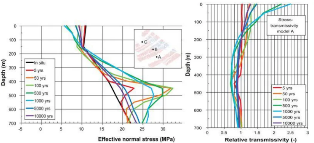
The change of transmissivity due to normal stress was calculated by SKB based on effective normal stress at selected vertical monitoring lines in the repository. The monitoring scanline A, B and C are indicated in Figure 13 together with the calculated relative transmissivity change. The increase in transmissivity was found to be around a factor of 2 along different scanlines throughout the cooling period of the repository up to 10,000 years (Hökmark et al., 2010). It is important to note, however, that these results are entirely dependent on the chosen stress-transmissivity relation for rock fractures. As the fractures at around 400 m depth are already close to residual aperture/transmissivity, normal stress changes of several MPa do not impact on the aperture variation. This is the main reason for a small variation in transmissivity calculated by SKB. As the normal stress reduces with time due to the cooling, SKB assumes that the transmissivity will recover to its initial value. When transmissivity change was analyzed in near-field fractures, the effect of relaxed stress around the tunnel had a direct impact on the transmissivity change up to a factor of 30 (Hökmark et al., 2006).
Figure 13. Effective normal stress as a function of depth along scanline B in the direction of the present-day minimum horizontal stress (left) and the relative transmissivity of vertical fractures striking perpendicularly to the present-day minimum horizontal stress (right) (Hökmark et al., 2010).
3.1.2. Transmissivity changes due to shear stress
There is no quantitative assessment of transmissivity change due to shearing in the SKB’s investigation for different phases of the repository development with time. The only results presented by SKB is the quantification of the shear displacement along fractures of different size, which is indirectly estimated by means of Eq. (2.5) and based on calculation of shear stress from 3DEC modelling.
The Mohr Circle representation of the thermal stress change showed that the shear failure along the fractures can occur (Figure 14, left). Shear displacement with fracture half-lengths of 150 m was calculated to be 27.8 mm at 450 m depth on scanline A between two deposition panels (Figure 13 shows the location; Figure 14 right). As shear displacement is assumed proportional to the size of the fractures, the magnitude of displacement of smaller fractures can be readily scaled. For example, a fracture with 30 m diameter will undergo a shear displacement larger than 5 mm. Although dilation angles of 3.2° (based on normal stress 20 MPa; SKB, 2010, p. 38) or 10° (Fälth and Hökmark, 2006, p. 45) were used for the numerical simulation, it is not clear how this value was actually incorporated into the results. Importantly, this analysis shows that the shear displacement would recover to its initial value after 10,000 years indicating that SKB’s model shows nearly elastic response of the fractures (see Figure 14).
Figure 14. Stresses on modeled factures plotted on Mohr-Coulomb circles (left) and shear displacements as a function of the fracture radius (right) around a deposition tunnel at different times after closure of the repository (Hökmark et al., 2010).
3.1.3. Spatial extent of transmissivity changes
The regional extent of transmissivity change investigated by SKB is summarized in Figure 15. Hökmark et al. (2006) estimated that within a distance of 2 m from a depositions tunnel, the relative transmissivity may increase by up to two orders of magnitude. No changes were predicted elsewhere. This observation is applicable to the thermal phase of the repository. The changes of transmissivity in the near-field were mainly due to normal stress relaxation close to the tunnel opening, and the contribution of shear dilation was only qualitatively considered by Hökmark et al. (2010). Therefore, the spatial extent of transmissivity at larger scale has been totally overlooked by SKB in the region outside a distance of 2 m from the tunnel opening. It is also noted that the size of analyzed fractures was a few tens of meters and their orientation did not have bearing on fracture observations at the Forsmark site (Hökmark et al., 2010).
Figure 15. Summary of the transmissivity changes calculated by SKB for the near-field of the repository. The shaded areas around the tunnel represent the spatial extent of volume with increased transmissivity (Hökmark et al., 2006; Hökmark et al., 2010).
3.2. Motivation of the assessment on the evolution of
fracture transmissivity during the thermal
phase based on independent TM modelling
For this review assignment, independent modelling of the behavior of the fracture network and the evolution of the fracture transmissivity during the thermal, glacial and earthquake loading was carried out by the Authors. Table 2 lists the conducted modelling in this study.
3.2.1. Data and geometry for the independent TM modelling
Data and geometry for modelling were taken from SKB’s repository Layout D2 (SKB R-08-83, 2009). The spacing between deposition tunnels is 40 m and the spacing between deposition holes in each tunnel is 6 m. The most likely values and orientations of in situ stress are based on the SKB’s data report (SKB TR-10-52, 2010). Therefore, it is assumed that the deposition tunnel axis is parallel to the
shown as a green dot in Figure 16a, is 55° with respect to North. A true 3D-DFN model was cut through three sections. Firstly, the NE section in Figure 16b is the 2D section whose normal line is parallel to the maximum horizontal stress direction and to the direction of a deposition tunnel axis. Therefore, in the Authors’ modelling, the NE section is subjected to the minimum horizontal stress and vertical stress.
Similarly, the NW section is the plane subjected to maximum horizontal stress and vertical stress. Lastly, HZ section is subject to the maximum horizontal stress and minimum horizontal stress. These sections are indicated in Figure 16c. The magnitude of each of the in situ stresses used for the modelling is listed in Table 3 together with their stress gradients with depth. The initial temperatures at a depths of 400 m, 500 m and 600 m were 10.5 °C, 11.6 °C and 12.8 °C, respectively. The mechanical and thermal properties of rock mass and fractures around the deposition hole are summarized in Table 4 and Table 5.
Table 2. List of modelling cases for thermal, glacial and earthquake scenarios.
Scenario 2D section DFN Results
Thermal Vertical (NE) T_NE02 Section 3.2.5.1
T_elNE02 Section 3.2.5.1
Vertical (NW) T_NW02 Section 3.2.5.2
Horizontal T_HZ02 Section 3.2.5.3
Far-field Deformation zone Section 3.2.7
Glacial Vertical (NE) TG_NE02 Section 4.2.4.1
Vertical (NW) TG_NW02 Section 4.2.4.2
Earthquake Vertical (NE) TGEQ_NE02 Section 5.2.4.1
Vertical (NW) TGEQ_NW02 Section 5.2.4.2
Table 3. In-situ stress distributions at Forsmark used for independent TM modelling (from Hökmark et al., 2010). z is the depth.
For depth > 400m Unit Stress
Maximum horizontal stress (𝜎𝐻) [MPa] -29.5 - 0.023 · z
Minimum horizontal stress (𝜎ℎ) [MPa] -9.2 - 0.028 · z
Vertical stress (𝜎𝑣) [MPa] -0.0265 · z
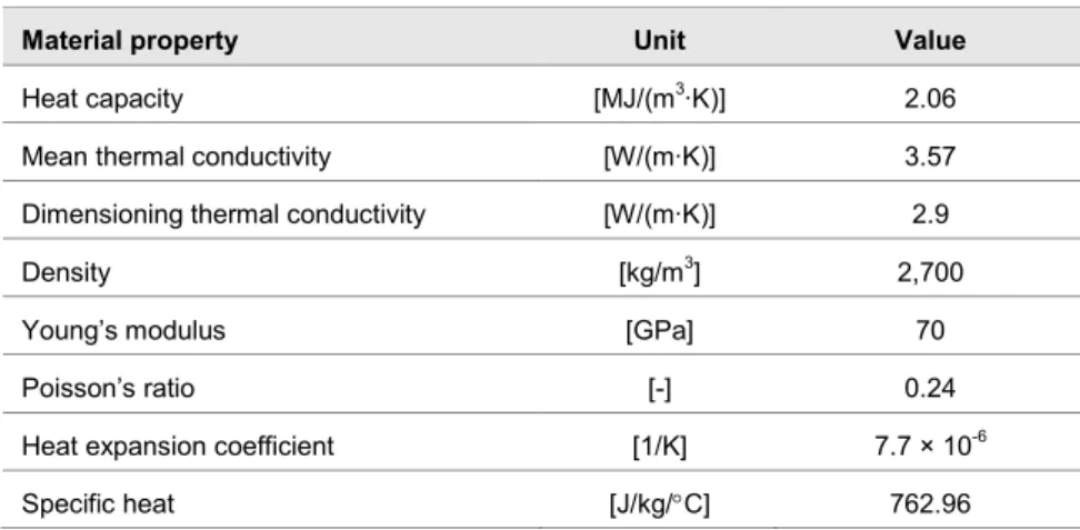
Table 4. Thermal, thermo-mechanical and mechanical properties of the rock mass used for the independent TM modelling in this study (from Hökmark et al., 2010).
Material property Unit Value
Heat capacity [MJ/(m3∙K)] 2.06
Mean thermal conductivity [W/(m∙K)] 3.57
Dimensioning thermal conductivity [W/(m∙K)] 2.9
Density [kg/m3] 2,700
Young’s modulus [GPa] 70
Poisson’s ratio [-] 0.24
Heat expansion coefficient [1/K] 7.7 × 10⁻⁶
Table 5. Mechanical properties of the rock fractures from domain FFM01 at Forsmark used for the independent TM modelling in this study (from Hökmark et al., 2010).
Material property Unit Value Comment
Shear stiffness [GPa/m] 34
Normal stiffness [GPa/m] 656
Friction angle [] 35.8
Dilation angle [] 3.2
Cohesion [MPa] 0.5
Tensile strength [MPa] 0
Z-dilation [m] 3 × 10⁻³ Critical shear displacement
when dilation stops Residual aperture [m] 2 × 10⁻⁵
Zero aperture [m] 3 × 10⁻⁵
It is noted here that each 2D section can greatly reduce the true connectivity of the discrete fracture network (DFN). On the other hand, however, it is also noted that 2D DFN can overestimate the shear displacement compared to 3D models with DFN because 2D DFN sections implicitly assume infinitely long planar fractures in the direction perpendicular to the model plane.
Considering the symmetry of the deposition tunnel arrays, the width of the NE and NW model was chosen to be 40 m and its height to be 100 m, which provides a reasonable geometrical approximation for the temperature boundary conditions (Figure 17). In order to represent an array of deposition holes in a deposition tunnel in 2D NE section, one target deposition hole with a heat source, was located in the center of the model. In NW section, five deposition holes were presented along the tunnel direction. In NW section, heat sources were also adjusted due to the effect of two-dimensional analysis. Furthermore, in HZ section, the length of square is chosen as 70 m to reduce the effect of fixed temperature at boundaries. Five canisters within deposition holes were modeled as heat sources as shown in Figure 17c.
It is noted that explicit mechanical excavation was modeled only for the deposition tunnel in NE section. The excavation of deposition hole was not modeled in order to avoid complexity in the interpretation of results. This approach is justified given that the regional extent of stress concentration around the deposition hole is expected to be small in the order of less than 1 m. Furthermore, deposition tunnel in NW section cannot be modeled because deposition tunnel is through-going along the NW section. Therefore, the results obtained from thermomechanical analysis is affected mainly by thermal loading except for the region close to deposition tunnel in NE sections. The transmissivity is calculated from the mechanical aperture based on Eq. (2.2) and its relationship is plotted in Figure 7a. It is noted that, for simplicity, no distinction has been made in this study between hydraulic and mechanical aperture. The analyses of all models were conducted using the two-dimensional discrete element
(a) (b)
(c)
Figure 16. In-situ stress orientation and the 3D DFN for the independent TM modelling. (a) mean value orientations (poles) and ranges of uncertainty (dashed lines) of the principal in situ stress components (from Hökmark et al., 2010); (b) scheme to cuts of the 3D DFN-model according to the principal stress planes NE, NW and HZ. (c) DFN sections of the 3D DFN and boundary in situ stresses.
(a) (b)
(c)
Figure 17. Model geometry for TM modelling in this study. (a) the tunnel geometry and boundary conditions in the NE section. Five monitoring points A to E are placed on a horizontal line departing from the center of the canister at distances of 0.5251 m, 0.8751 m, 5.91 m, 10.35 m and 14.91 m, respectively; (b) tunnel geometry and boundary conditions in the NW section; (c) geometry of five deposition holes and boundary conditions in the HZ section. The size of the vertical section models is 40 m × 100 m (width × height). The size of the HZ section models is 70 m × 70 m (width × height).
3.2.2. Thermal loading
The stress distribution and the temperature of the rock mass will change due to heat released from the canisters with the spent fuel. The deposition holes are located at 468 m depth, and are represented as rectangular elements in the two-dimensional
dependent function with given decay rate from an initial value P(0). The decay of the canister power is applied as heat source using Eq. (3.1) and the coefficients ti and ai are listed in Table 6:
7 1
( )
(0)
iexp
i it
P t
P
a
t
Eq. (3.1)The function P(0) and Eq. (3.1) are adapted in order to provide input data to the UDEC modells for a time period of 100,000 years. Figure 18 shows the resulting power function P(t) used for the thermo-mechanical modelling. Heat generation starts with an initial value P(0) of 1700 W for the first year, and decays nearly to zero after 10,000 years.
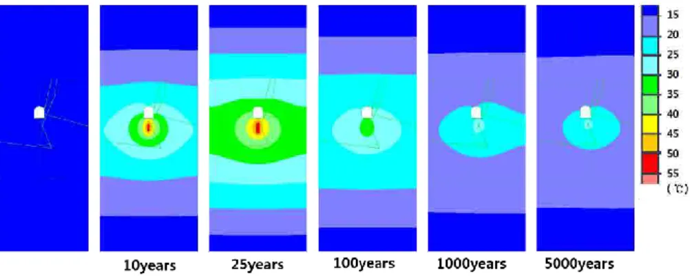
Coupled thermo-mechanical analysis was conducted with in situ stress and initial temperature distribution in accordance with data from the Forsmark site. TM analysis provided the evolution of temperature distribution and thermal stress. Figure 19 describes the temperature variation due to heat generation of the canister for 100,000 years. The variation of measured temperatures at five points A to E
Table 6. Canister power decay coefficients for Eq. (3.1) for SKB’s reference fuel (Hökmark et al. 2010). Time interval i ti [years] ai [-] 1 20 0.060147 2 50 0.705024 3 200 -0.054753 4 500 0.249767 5 2000 0.025408 6 5000 -0.009227 7 20000 0.023877
Figure 18. Decay of the generated heat power by one canister with time to be used for the UDEC modelling.
(a)
(b)
Figure 19. (a) temperature evolution in the various locations of the repository; (b) temperature versus time along the horizontal monitoring line at point A to E at a depth of 468 m across the repository.
along the horizontal line at 468 m depth is shown in Figure 17. The maximum temperature at each point occurs after 25 years and is presented in Figure 19b. As expected, the temperature increases most for monitoring points close to the canister. The horizontal and vertical stress distribution and displacement with time are provided in Figure A3-1 in Appendix 3. The results show that the elevated stress and displacement in the rock recover to their initial value after 5,000 years.
Further, the stresses at each monitoring point has its maximum magnitude at around 25 years after start of deposition, and returns to their initial in situ stress value after around 1,000 years. Especially the horizontal stress at the vicinity of the canister wall increases from around 22 MPa to around 50 MPa as shown in Figure 20a. The vertical stress shows different tendencies depending on the location as shown in Figure 20b. At point A, which is at the center of the deposition hole, the vertical stress increase was modest and about 10 MPa. However, most of the locations around the repository do not show notable increases in vertical stress because the overburden is free to move upwards, unlike the case for horizontal stress. In general, vertical stress does not vary much except below the deposition tunnel.
(a)
(b)
(c)
Figure 20. Thermal stress evolution at control point A to E of the NE section at a depth of 468 m in Forsmark. (a) minimum horizontal stress, (b) vertical stress, (c) stress ratio.
The ratio of the horizontal stress to vertical stress can be also studied with time. As shown in Figure 20c, the stress ratio becomes greater than 2.5, which is a critical value that triggers shear slip on fractures in all monitoring points (except for the
location inside the deposition hole). From these results, it is noted that the stress ratio can be high enough to produce shear slip on fractures at points about 15 m away from the canister. This observation provides a good indicator for evaluating the spatial extent of fracture transmissivity change induced by shear slip on rock fractures.
3.2.3. Conceptual model of fracture transmissivity evolution
during the thermal phase
Before conducting the DFN-DEM analysis with DFN data from Forsmark, conceptual models with a single fracture were used to gain an insight into shear behavior during the thermal loading phase. A conceptual model was studied with a rock block of size 40 m × 40 m containing a single fracture as shown in Figure 21a. According to Pollard and Segall (1987), the relative shear displacement (Δu) within a fracture is calculated using the following equation:
2 1
2 2 r cu
a
x
G
Eq. (3.2)where 𝜏𝑟 is the remote shear stress, 𝜏𝑐 is the shear stress on the crack, 𝜈 is the Poisson’s ratio and G is shear modulus of the rock, a is half fracture length, and x is the distance from the center of the fracture. Note that this equation is a 2D version of Eq. (2.5). (𝜏𝑟− 𝜏𝑐) is 5 MPa in this model, and the friction angle and cohesion of the fracture are assumed to be zero.
Comparison between the UDEC and analytical result from Eq. (3.2) as presented in Figure 21b that shows there is a good match between the two. The redistributed directions of the principal stresses at the vicinity of the fracture are shown in Figure 22.
(a) (b)
Figure 21. (a) generic model in the size of 40 m x 40 m containing a single fracture with half-length of 4.84 m. The boundary stress condition is indicated in the top right corner; (b) relative shear displacement versus distance from center of the fracture.
(a) (b)
Figure 22. (a) Principal stress distribution in the generic model and (b) close-up of the stress distribution around to the fracture.
Conceptual models for thermo-mechanical analysis are conducted with different fracture sizes and orientations as shown in Figure 23 and Figure 24.The distance between the fracture and center of the heat sources is 5m to avoid intersection with the heat source block.
Figure 23. Illustration of the conceptual models of a single fracture the below the deposition hole modelled with UDEC for different (a) fracture lengths and (b) fracture orientations.
Figure 24. Geometry of conceptual model of a single fracture below a deposition hole with the heat source. Heat is generated at the center of model (0, -468m) and the center of the single fracture is at (0,-473m).
Figure 25 shows maximum shear and normal displacements of the single fracture for different fracture lengths. The friction angle of the fracture is assigned as 35.8. As expected from Eq. (2.5), longer fractures show larger displacements for the same applied stress. The increase of fracture transmissivity is around one order of magnitude for the case of a 30 m long fracture. Figure 25c shows the increased transmissivity calculated using the change of mechanical aperture. An important observation from the modelling is that the increased transmissivity due to dilation does not return to its initial state after removing the load. As shown in Figure 25d, and unlike the SKB’s estimation presented in Figure 13, the relative transmissivity remains after the heating cycle.
(a) (b)
(c) (d)
Figure 25. Fracture displacement and aperture evolution for various fracture lengths below a heat source during a time period of 10,000 years. (a) shear displacement, (b) normal displacement, (c) transmissivity and mechanical aperture, and (d) stress and relative transmissivity.The friction angle of the fracture is 35.8°.
(a) (b)
Figure 26. (a) magnitude of the displacement in the rock and (b) normal displacement of a fracture with length 30 m. Thermal stresses at centre of model make the fracture to displace and open (joint opening). The friction angle of the fracture is 35.8°.
Figure 26 represents the magnitude of the displacement in the rock and joint normal displacement fracture of 30 m length inclined 27.5 and at 500 years after start of the heating. That greater increase of the normal displacement at the right side of fracture is because of the vicinity to the heat source location.
The influence of fracture orientations on transmissivity was studied with fracture inclinations of 0°, 15°, 27.5°, 35°and 45°. Among the TM analyses, the one with the fracture dipping 45° shows the largest shear displacement for the assigned stress variation because it has the closest distance between fracture and heat source (Figure 27). In addition, the location of the maximum shear displacement is at the right side of the fracture because that side is closer to the heat source. The fracture with orientation 0° showed the least displacement among all the studied fracture orientations. All the different fracture orientations simulated except the
0° orintation show a remaining dilation and relative transmissivity following the cooling of the repository after 10,000 years.
(a) (b)
(b) (d)
Figure 27. Fracture displacement, aperture and transmissivity evolution of a 30 m long fracture with different orientation located below a heat source during of a period of 10,000 years. (a) shear displacement, (b) normal displacement, (c) mechanical aperture and transmissivity and (d) relative transmissivity and stress.
Figure 28. Possible ranges of relative transmissivity with respect to initial mechanical aperture. The gray area is the possible ranges of fracture transmissivity when initial mechanical aperture varies from 5 μm to 50 μm. The relative transmissivity changes by zero to two orders of magnitude for the specified aperture change. Investigation is made on a 30 m long fracture with 27.5° dip angle located below a heat source.
The shaded areas in Figure 28 show the possible range of relative transmissivity with respect to initial mechanical aperture. The modelling results show that relative transmissivity is greatly dependent on the initial mechanical aperture. The relative transmissivity increases by one order of magnitude for an initial aperture of 30 μm. For fractures with initial aperture of 5 μm, the relative transmissivity can increase by two orders of magnitude. The relative transmissivity change is a function of initial aperture since initial aperture is placed in the denominator in Eq. (2.3) for
calculating the relative transmissivity. For initial apertures of around 100 μm and larger, the relative transmissivity change is less than one order of magnitude throughout the entire time period of 10,000 years.
3.2.4. Discrete Fracture Networks (DFN) for the independent
TM modelling
Fracture data used for this study are based on rock domain FFM01 at Forsmark. Ten DFN realizations for each section were generated on behalf of SSM according to the fracture density and orientation data from Forsmark (Fox at al., 2007) as shown in Figure 29 to 24. The DFNs were initially constructed in 3D, and later cut into 2D sections at a depth of 468 m. 2D sections were extracted according to Figure 16. Full descriptions of DFN used for this study is provided in Appendix 2.
As it can be seen in Figure 29 to 24, the DFN realizations have generally poor connectivity. Only one realization (DFN02) out of ten DFN realizations ensures some level of connectivity for further investigation. Therefore, the Authors chose DFN02 which showed the greatest connectivity for further analysis. For the chosen DFN, three sections (NE, NW and HZ sections) are used for thermo-mechanical analysis. The DFN section NE02 (vertical section which the strike direction is N55E) is subjected to the minimum horizontal and vertical stress, and therefore minimize