http://www.diva-portal.org
Postprint
This is the accepted version of a paper published in . This paper has been peer-reviewed but
does not include the final publisher proof-corrections or journal pagination.
Citation for the original published paper (version of record):
Heikkinen, T., Johansson, J., Elgh, F. (2020)
Multidisciplinary design automation – A conceptual framework for working with
product model extensions
International Journal of Agile Systems and Management, 13(1): 28-47
https://doi.org/10.1504/IJASM.2020.105866
Access to the published version may require subscription.
N.B. When citing this work, cite the original published paper.
Permanent link to this version:
Multidisciplinary Design Automation – A Conceptual
Framework for Working with Product Model Extensions
Tim Heikkinen, Joel Johansson, and Fredrik Elgh
School of Engineering, Jönköping University, Gjuterigatan 5, 553 18 Jönköping Email:
tim.heikkinen@ju.se
Email:joel.johansson@ju.se
Email:fredrik.elgh@ju.se
Abstract: Design automation can be used to support efficient information handling and knowledge
processing in computer-based product modelling, as well as make possible new design exploration and optimisation capabilities. To be able to utilise and manage design automation systems over time, it is important to understand how the disciplinary methods and models are dependent on each other through the product model constituents and then how these relations should be built to support maintenance, leveraging and future reuse. Awareness of the concrete representation of relations could support the system’s traceability and transparency, and depending on the chosen technique, comprehension and extendability can be affected. This paper presents a conceptual framework for how a set of product model constituents are, can and to some extent, should be extended to define relations in multidisciplinary design automation systems.
Keywords: Multidisciplinary design automation, system relations, extended product model Biographical notes: Tim Heikkinen is a PhD student within Product Development at Jönköping
University. He has an interest in design automation and has focused his research on the relations between methods and models within multiple disciplines and how a structured realization approach could help support a successful implementation, maintenance, and future reuse.
Joel Johansson holds a PhD in Product and Process Development from Chalmers University of Technology and got a position as Associate Professor in Product Development 2018. His research has considered the flexibility of design automation systems, knowledge bases containing conflicting rules, the automation of the finite element analysis process, and complexity management in design automation.
Fredrik Elgh is Full Professor of Product Development at Jönköping University. He holds a MSc in Mechanical Engineering and a PhD in Product and Production Development from Chalmers University of Technology. He has extensive experience of externally funded research projects executed in close collaboration with more than 50 companies and has published more than 90 scientific papers. Earlier work includes cost engineering, design for producibility, design automation and knowledge-based engineering, while later work also targets design for additive manufacturing, design methodology, product platforms, knowledge engineering and lean management with applications in automotive, aerospace, mechanical, consumer, and house-building industry.
1 Introduction
The ability to efficiently and effectively provide custom products has been identified as a competitive advantage. Product configuration has been shown as an effective way of achieving this ability through an approach that combines modularisation and product platform and product family development (Pakkanen et
al., 2016). Modularisation is a process of partitioning a product into blocks. The reasons for doing so can be
found throughout the product life cycle, such as carry-over, technological evolution, planned design changes, process and/or organisation reuse, and so on (Erixon, 1998). Product platform development emphasises the reuse of shared aspects of a set of products (Robertson and Ulrich, 1998). Product family development focuses on the definition of necessary product variants to fulfil a market’s needs in a predictable future (Lehtonen et al., 2003).
A core assumption behind this approach is that the module variants and their constraints can be explicitly defined as product knowledge in terms of geometry and configuration rules. However, this is not always the case; many companies require extensive engineering to develop each variant and cannot afford to do so in order to meet all potential customer requirements in a predictable future (André et al., 2017). Instead, they implicitly define the module variants by explicitly defining the process knowledge of how module variants
can be realised. In this way, they can efficiently realise module variants on demand when the customer requirements are better defined, and the development can be justified by the increased probability of profiting from the outcome.
Developing a product (or a module variant) is a continuous cycle of synthesising and analysing product specifications, such as requirements, bills of material, manufacturing equipment and delivery processes. The formal representation of the created product data is called a product model, which is structured according to a product information model that is supposed to support development activities (Yang et al., 2008). In practice, product models are commonly constructed digitally, utilising various Computer-aided technologies (CAx), spreadsheet applications, word processors, text editors, and so on. These tools all use their own information models, focused on different data types and for various purposes. It is then up to the users themselves to utilise these tools to form coherent product models.
Design automation can be used to support efficient information handling and knowledge processing (Elgh, 2007) in computer-based product modelling, as well as make possible new design exploration and optimisation capabilities. It results in a collection of methods and models, which can come in the form of computer scripts, parametric computer-aided design (CAD) models, template spreadsheets, and so on. These methods and models are developed and maintained within the different disciplines involved and are dependent on each other through related product model constituents. To support efficient and effective information exchange, using product model constituents across activities, disciplines and projects, it is necessary to include information that is more related to the process rather than the product specifications themselves. Process-related information can be found in many different forms, such as custom-named features in CAD models or notes on spreadsheet cells, and can be human and/or computer interpretable. The information can be used as an identifier for input, handles or containers for downstream methods and models. To be able to utilise and manage design automation systems over time, with respect to process iterations and the introduction of new or updated technologies and organisational changes, it is important to first understand how the disciplinary methods and models are dependent on each other through the product model constituents and then how these relations should be built to support maintenance, leveraging and future reuse. This paper presents a conceptual framework for how a set of digital product model constituents are, can and to some extent, should be extended to model these process-related relations. The objective is to find out how a systematic approach to product model extensions can be used to support multidisciplinary design automation. Called an extended product model (EPM), the overarching framework is an extract from four supporting case studies involving three companies. The focus has been on multidisciplinary design automation of different kinds in a mechanical engineering context.
2 Related work
An EPM concept is presented in a paper (Ding et al., 2007) to support a constraint-based redesign approach. It is centred on CAD models that are extended with requirements, performance limits, alternative features and many different types of links for the active product model, as well as historical instances. The purpose is mainly to capture and represent design rationale in CAD models. The Lightweight Model with Multi-layer Annotation (LIMMA) (Ding et al., 2009) is a similar approach to the EPM described above [10]. However, LIMMA uses lightweight representations of geometry and an annotation mark-up approach stored inside or outside the CAD model in XML format to enable reviewing and editing outside the CAD environment.
Lundin et al. (Lundin et al., 2017) present a CAD model-oriented approach to support reuse in product family development. They suggest a support approach where capture and representation are enabled through a custom CAD application integrated in the CAD tool to facilitate minimum investment and maximum reuse. The application utilises 3D annotations associated with CAD features and model views, along with textual descriptions and links to external sources. All of the information is then managed by a product lifecycle management system, which can be accessed and visualised using web applications. A set of six challenges is also presented, highlighting dimensions such as complete/abstract reuse, product family internal/external reuse, level of built-in design module complexity and number of design modules, structured methods and designer flexibility, investment (generally unappreciated documentation efforts) and actual return (achieved reuse), and general knowledge about the dependencies in the development process.
Computer-based product modelling has been developed from being focused on solid geometry, such as boundary representation (B-Rep) and constructive solid geometry (CSG), to being feature based, knowledge based and integrated (Yang et al., 2008). In contrast to B-Rep and CSG, feature-based product modelling also focuses on non-geometric aspects and enables reasoning about sets of information on a product (Salomons et al., 1993). Feature-based modelling therefore supports the integration of downstream
processes, such as net shape design (using moulds or dies, in contrast to material removal processes) (Chen and Wei, 1997). Knowledge-based product modelling further expands the modelling capabilities by incorporating product knowledge in terms of rules that enable the use of technologies developed in research on artificial intelligence, such as knowledge-based systems. Integrated product modelling incorporates geometric, feature-based and knowledge-based methods in one model to support integrated product development.
The model-based enterprise (MBE) is a paradigm or a concept that has broadened the model-based definition (MBD) methodology (Miller et al., 2017). Instead of only using model-based information as a way of replacing 2D drawings with 3D CAD models, the MBE has been described as a general way of supporting information consumption in any activity within an organisation. Many of the examples found revolve around annotating 3D-CAD models as a means of making the geometry more comprehensive and in this way, make them more reusable (Trainer et al., 2016), stored inside or outside the actual CAD model (Camba et al., 2014).
Standard product models, such as ISO 10303 Standard for the Exchange of Product Model Data (STEP), focus on the representation of product data to enable interoperability throughout the product life cycle and long-term storage and retrieval. These models have been developed, from mainly focusing on the representation of design output in the form of geometry to non-geometric information, such as geometric dimensioning and tolerance. Core Product Model 2 (CPM2) (briefly described in (Fenves et al., 2008)) is another product model concept that further expands the scope to support information regarding geometry, function, form, behaviour, material, and so on.
Knowledge-based engineering (KBE) is usually referred to as a method for the capture and reuse of product and process knowledge to automate repetitive tasks (Stokes, 2001). Essentially KBE is knowledge-based systems theory applied to the engineering field (Rocca, 2012) which originates from research within artificial intelligence. It can be seen as the connection between CAD and computer-aided analysis tools, including the reasoning and knowledge capturing and representation provided by knowledge-based systems (Rocca, 2012). Several supporting methodologies have been outlined for the development of KBE applications. ‘Methodology and software tools Oriented to Knowledge based engineering Applications’ (MOKA) is probably the most well-known and provides tools to capture and model engineering knowledge in a suitable manner for the use in KBE systems (Stokes, 2001). MOKA mainly focuses on the structure of capture and formalize stages of the KBE life-cycle but emphasizes the importance of each. Verhagen (Verhagen, 2013) outlined a number of shortcomings with MOKA and other available methodologies such as: investigation of the nature and consequence of changes in knowledge, adoption of methodologies, and quantitative evaluation capabilities. A new methodology is then outlined called ‘Knowledge capture and identification of knowledge change, Normalization, Organization, Modelling and implementation, Analysis, and Delivery’ (KNOMAD) focusing on these shortcomings.
In more recent systems, service-oriented system architectures have been applied to enable distributed design (Lyu et al., 2017). SORCER as applied and described in (Li, 2015) is one such technology which wraps design resources, such as design tools (software and hardware), knowledge resources (books, papers, historical data etc.), as well as intelligent resources (engineers, organizers, artificial intelligence etc.), as services which can then be used to handle the subtasks of a design process.
Multidisciplinary design optimization (MDO) is a field of research which focuses on mathematical modelling of design problems and taking advantage of different optimization techniques to find the best solutions according to some objective function under relevant constraints. It depicts the pinnacle of design automation where all design solutions can be synthesized and assessed automatically within an area of interest. However, the difficulty in modelling all relevant aspects, such as non-technical disciplines (Cees, 2015), restricts many systems to sub-optimisation.
Similar to the objectives of the MBE and standard product model research, the EPM framework presented in this paper focuses on how to support an efficient and effective exchange and integration of information throughout the product realisation process. Similarly, to KBE methodologies, the EPM framework aims to reduce the risks involved with the development of design automation systems but with a focus on the realization phase. Service-based architectures and MDO are interesting technologies for enabling distributed and algorithm-based design respectively, the EPM framework focuses on supporting a working, maintainable, and re-usable base on which these can be added. The perspective is in other words on how the current technical possibilities are, can and should be used in industrial practices to support multidisciplinary design automation.
3 Method
The conceptual framework for how product models can, are and to some extent, should (if needed) be extended with process-related information has been developed by examining a Swedish industrial company in detail and two additional ones in general. The detailed case builds on the automation of tool-insert development to form a sheet-metal component (T. M. D. Heikkinen et al., 2018). The general cases have mainly been based on an interview study (Heikkinen et al., 2017) that focuses on a specific product model constituent (CAD models). Focusing on CAD-models was done in part to concentrate the work but also due to its central function in mechanical engineering design processes.
4 Extended product model
In this paper, product model is defined as the formal representation of all product realisation outputs. Within the product and production development phases of product realisation it is comprised of both product and manufacturing specifications that are formulated in a design process by utilising different views of the information (Shooter et al., 2000). In the end of product and production development it should represent a complete and unambiguous recipe from which individual products can be manufactured and to which subsequent product life information can be further attached. The product model is often the result of combined efforts from multiple disciplines and computer-based tools.
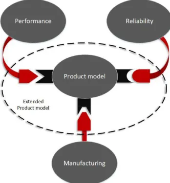
EPMs include information relating to the process of developing them. Extensions can be made not only to aid in an efficient and effective information exchange between development activities but also to resolve how the product model has become what it is. This question can be important in the development projects themselves, in future projects and when developing the process. Figure 1 graphically depicts an EPM to which different interfaces have been added (black sockets), enabling any discipline, focused on performance, reliability or manufacturing, to connect or relate its methods and models to the common product model.
Since the purpose of EPMs is to support information exchange and integration within design automation systems, the digital product model constituents and the design automation systems are addressed in Sections 5 and 6, respectively.
5 Digital product model constituents
In the field of mechanical engineering, geometry is of interest in many of the disciplines involved in developing product models (probably because it is the main deliverer of function in mechanical products). Geometry is in turn commonly modelled by utilising CAD software.
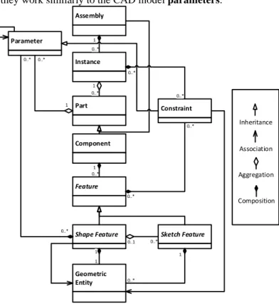
Figure 2 shows one way to represent a parametric CAD model (influenced by (T. Heikkinen et al., 2018) and (Johansson, 2017)). In the figure, a CAD model comprises an assembly or a component, both inheriting the part class. An assembly can then have instance objects, which in turn can have other assemblies or components. The instance object is used to define the context-specific information, such as location in the local coordinate system, colour, and so on. Each component is a collection of features, which in this context is categorised as shape and sketch. Shape features refer to those that are directly coupled to the geometric shape. Inputs to these features can be parameters, constraints (e.g., “up to next surface”) or references to
sketch features. A sketch feature comprises a collection of 2D geometric entities and is often utilised by
a shape feature. A geometric entity is a point, curve, surface or body, including supporting reference geometry, such as reference planes and axes. Parameters can be a variable-value pair (e.g., a variable named “length” paired with a value of “5 mm”) or a variable-formula value calculated by interpreting the formula (e.g., area = length * length). A constraint is a type of parameter that can reference geometric entities and contains logical expressions (e.g., “up to next surface”). Constraints are used by instance and feature objects to constrain their constituents in the local coordinate system.
In addition to CAD models, spreadsheet, word and text files are common digital product model constituents that employ their own information models. In the work conducted so far, CAD models have always been part of the product model constituents that have been transferred forward in the development process and utilised by methods and models in other disciplines. Spreadsheet models have also been common components.
Figure 3 shows one way to represent a spreadsheet model (influenced by (Johansson, 2017)). In the figure, a spreadsheet comprises a book object that contains one or several sheets. A sheet then contains a collection of cells. A cell is an object that has a value and a formula property. Formulas can be used to reference other cells; they work similarly to the CAD model parameters.
Assembly Parameter 1 0..* Component Shape Feature Instance 1 1 1 0..* Part 1 0..* 1 0..* 0..* 0..* Sketch Feature Feature 0..* 0..1 0..* Geometric Entity Constraint 0..* 0..* 0..* 0..* Inheritance Association Aggregation Composition 1
Cell Sheet Book 1 1..* 1 1..* - Formula - Value
Figure 3. Spreadsheet model class diagram.
6 Design automation systems
A system can be defined as “a regularly interacting or interdependent group of items forming a unified whole” (Merriam Webster, 2018). Design automation systems usually comprise computerised items that support engineers in a phase of a design process (Johansson, 2011). Design automation systems are developed by formalising and systematising design processes that result in a collection of pre-planned reusable assets. Most engineers encounter repetitive work and implement some level of automation, such as drawing templates and spreadsheet scripts. A design automation system can vary in the degree to which human interaction is required. However, to be considered an automation system, it needs to perform some activity.
With this broad definition, it can be argued that any software system utilised by engineers is also a design automation system. Looking at a word processor, such as the one in which this article is written and also widely used in engineering design processes, much of the work, especially in editing the text, would have required some manual work in the past (moving text around would require erasing and rewriting the text). Thus, to some extent, the cited argument might be true, and it might be more relevant to discuss levels and types of automation. A study (Parasuraman et al., 2000) presents a level of automation (LoA) scale from 1 (no assistance is given) to 10 (the system is completely autonomous and ignores the human agent), along with four types of automation: information acquisition, information analysis, decision selection and action implementation. Figure 4 shows how a system can vary in its LoA and type.
High Low High Low High Low High Low Information Acquisition Information Analysis Decision Selection Action Implementation Le v el of A ut om at io n System A
Figure 4. Types and levels of automation for a system (Parasuraman et al., 2000).
This paper makes a distinction in the type of computerised items (pre-planned reusable assets) in terms of the method, which describes a procedure (how to do something), and the model, which describes an artefact (what something is). Methods can also be active or passive in terms of whether they are only being interpreted and followed (active) or copied and configured (passive).
Methods can be formalised as both human and computer interpretable. Exclusively human-interpretable methods can be design guidelines or lessons learned, usually documented as text in text, word or presentation file formats. Exclusively computer-interpretable methods are compiled codes, such as executable files and shared libraries (e.g., dynamic-link libraries). Methods that fall in between the spectrum are non-compiled codes and some mathematically modelled methods, such as scripts and calculation-procedure modelling in Microsoft Excel™ or Mathcad™, for instance.
Models can also be either human or computer interpretable or both, in the sense that a human- or computer-interpreted method or both can or cannot be associated with them. Digital models could more often than not become computer interpretable by creating computer code, but this might also not be the case, depending on the level of automation possible and the value gained by making them. Models can be further divided into synthesis/assessment focused or generative/predictive focused. Examples of synthesis models are parametric CAD models, template spreadsheets or template word files. Examples of assessment/predictive models are calculation models or simulation models.
7 Industrial case – Case 1
This section presents a detailed use case for an EPM, involving a company (Company I) that develops and manufactures products that support an active lifestyle. It is a global manufacturer with about 2,200 employees worldwide. Some of its products are transport centred (e.g., roof boxes and bike carriers). It makes roof racks for cars, an important product line for the company because other products are attached to it. Each roof rack is engineered to meet the unique geometric specifications of each car model, and the goal is to have roof racks available for 95% of all cars. It is a representative case where a product configuration approach is advantageous but requires more than geometry and internal configuration rules.
One module variant, also known as an adaption kit, is composed of a rubber pad that sits on top of the roof and a sheet-metal bracket grasping a hold of the side. It is the only part in direct contact with the car, which makes it vital for safety and therefore needs to be developed and assessed for each car model separately. Additionally, due to the close geometric dependency and an incredible number of configurations possible, it is implausible to assure or explore the entire design space proactively.
Figure 5. Bracket component (left) of roof-rack adaption kit, tool insert (middle) and initial documentation
(right).
To enable a product configuration approach, the design process included in developing the adaption kit has been automated (Johansson and Elgh, 2017) for several years now. One phase of the process that is detailed here is the production development where new tool inserts, including the documentation, are required for the bracket components (see Figure 5). The purpose of this case study was to formalise and automate the tool-insert development process. The process was well established; however, no methods were formalised.
Figure 6 shows an overview of the tool-insert development process, including software tools, as well as methods and models (collectively named design assets) in each activity. It was decided that the initial three activities would be automated to the extent possible because they were confined to one department of the organisation and performed completely in a digital environment. The three activities involved the following: 1. Receive an order by email and retrieve the bracket CAD model from the product data management
system.
2. Model the tool inserts by utilising a tool-template CAD model (Design asset 1) using CAD software. 3. Start the initial documentation, including five sub-activities, as follows:
(I) Read the necessary machine bandwidth from a CAD model (Design asset 2) using CAD software and calculate the original sheet-metal length using a purchased CAD add-in. (II) Make a drawing utilising a drawing-template (Design asset 3) to generate 2D-geometric
depictions with some additional text and symbols, using CAD software.
(IV) Instantiate a tool-testing template (Design asset 5), which is used for documenting key parts of the development process, including the later stages of testing and possible refinements, using spreadsheet software.
(V) Finally, use the operation system to copy the folder structure template (Design asset 6), which is used to structure the results of upcoming test activities.
These initial three activities were recorded and then formalised and codified as a script. Several extensions were required to enact the script (a method), such as handles on a sketch in the bracket CAD model, which also required tangential inner faces. The script also needed handles on the methods and the models, in terms of geometric parameters and sketches to model the geometry, keywords to identify were to insert documentation specifics, constraints and look-up functions to automate bandwidth acquisition and finally, cell references to display information in multiple places.
OK? Not OK Start End OK Non-digital CAD add-in Spreadsheet Email CAD Design asset 1 Design assets 2-6 Documentation continued Get order Model punch and pad Initial documentation Testing Modify punch and pad PDM 1 2 3 4 5 6 7
Figure 6. Tool-insert development process, showing software tools, as well as methods and models
(collectively named design assets) used in specific tasks.
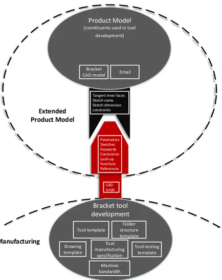
Figure 7 shows the extensions to the product model. Extensions are not always additional pieces of information, such as sketch names and dimensioning constraints, but can also be more qualitative, such as requiring tangential inner faces, as well as a standardised orientation.
Extended Product Model
Bracket
CAD model Email
Product Model (constituents used in tool
development) Parameters Sketches Keywords Constraints Look-up functions References Tangent inner faces Sketch name Sketch dimension constraints CAD script Manufacturing Bracket tool development Tool template Machine bandwidth Drawing template Tool manufacturing specification Tool-testing template Folder structure template
Figure 7. Example of an extended product model for a manufacturing-focused discipline (tooling).
8 Supporting industrial cases
To show that an EPM is not a completely isolated phenomenon in the case presented in the preceding section, three additional supporting cases are presented here. These EPM cases are mainly based on interviews with key employees. The interview study focused on CAD models as carriers of multidisciplinary information, presented in 2017 (Heikkinen et al., 2017), where multidisciplinary information was defined as any information that was not used to portray the final product form. In all three cases, the information was added to enable automation of different activities and can therefore also be viewed as extensions, as discussed here. It is worth noting that EPM constituents do not need to be centred on the CAD models. However, the results showed the CAD models as important carriers of process-related information in practice today, which was also speculated beforehand.
Case 2 – Company I
Case 2 involved the same company as in Case 1. Similar to the detailed previous case, extensions were required to enable automation in Case 2. Geometry and programmed features (macro features in Solidworks) were added to store information related to the simulation discipline to fully automate the creation of a finite element (FE) model. The programmed feature provided a way for the user to specify an FE feature, to add either a definition or a mesh component. Geometry was added when necessary and could be constrained to the traditional CAD model; it could then be pointed at from the programmed feature that required it. In the second automation system, section curves were added to the CAD model to enable a geometric search for previous solutions that might be possible to reuse.
The methods that utilised the information to produce an FE model or retrieve possible reusable solutions were modelled by using CAD software- and pre-processor software-specific Application Programming Interface (API) languages. The pre-processor-specific methods were made passive, meaning that they were
generalised so that the active CAD software-specific methods could copy and configure them as needed. This changed the dynamic of the methods and made extensions necessary.
Case 3 – Company II
In Case 3, the company supplies tools, tooling solutions and know-how to the metalworking industry and employs about 8,000 people worldwide. One part of the company develops parametrically defined product families with fully automated production specifications.
The main reason for adding extensions to the CAD model was to ease its reusability within CAD, Computer-aided Manufacturing (CAM), Coordinate measuring machines (CMM) and customers’ simulation software. Information was added in the form of reference planes, parameters, names, attributes and geometry. Most of the CAD models were then saved as UDFs (bundles of features), with the reference planes and parameters as inputs. An example of added information could be a point with tolerance information, stored as attributes, subsequently used by an automation system and interactively by engineers. The automation system utilises the information to build up the final CAD model, supporting CAD models for CAM and CMM, as well as simplified models for customers’ simulation software. It also simultaneously adds more information to the different parts necessary for downstream processes.
The methods were separated from the CAD software and the CAD models as much as possible by using a company-specific programming language. These methods used passive CAD methods in the same way that Company I applied passive pre-processor methods, copying and configuring them as required.
Case 4 – Company III
Finally, in Case 4, the company is a global actor in the development, production, service and maintenance of components for aircraft, rocket and gas turbine engines with high technology content. It belongs to a global group with approximately 60,000 employees worldwide and 2,400 in Sweden. The company provides completely custom-engineered products for an international market with high competition.
The main reason for adding extensions to the CAD models was to enable the automated creation of CAD and FE models. It was done by adding attributes to convey FE model-specific features, such as thicknesses (for shell models), material id, mesh quality, contact interface, loads, boundary conditions, thermal-analysis information, and so on, on points, lines, surfaces and solids, for example. Names were also added to convey mesh components, for instance, and as handles to automate the addition of downstream information. New geometric entities were also added, such as points (to convey load interfaces) and surface bodies (to convey boundary conditions). Programmed features (knowledge fusion, rule-based features) were added to read from spreadsheets and alter parameter values according to the information. Finally, parameters were also added to modify the geometry.
The methods were modelled by using CAD- and pre-processor-specific languages. At least one active method was employed for the creation of CAD models and another for the FE model pre-processing, using passive load-case methods.
9 Conceptual extended product model framework
Extending product model constituents has been shown as a common industrial practice and is done in several ways and for different purposes. The extensions can work as the connections between methods and models, both within and between disciplines. For such extensions to work as intended through product changes and software updates, it might be better to separate executable information, such as code, from software-dependent languages and API as much as possible. However, to support administration of the extensions, it might be better to also integrate tools in the software-specific environments.
The conceptual framework presented in this section highlights some features of design automation systems that are related to the choice of extension techniques. It is structured and presented in two parts. The first part, Overarching approach, discusses an important characteristic of the complete design automation system and how this plays an important role in choosing extension techniques. The second part, Extension
technique, outlines different extension techniques and four aspects to consider for each available technique
and model type. To choose an extension technique, the overarching approach and the evaluation of the model extension technique should be known and decided, preferably together with all employees involved in the system’s development, use and future maintenance.
Overarching approach
In the design automation systems investigated in the preceding sections, one particular difference lay in where and how many active methods were identified. In contrast to passive methods, active ones are not
copied and manipulated before execution, which means that they are hard coded in a way. A distinction is made in this regard for two reasons. First, passive methods require extensions to be configurable. Second, passive methods can be easier to leverage or reuse in other systems.
Company I used one active method for each automation system in the CAD software, building pre-processor scripts and searching a database of previous solutions, by looping through the CAD-feature history. Company II applied a CAD-external active method, building CAD scripts to form CAD models for CAM, CMM and FEM by interpreting its own programming language. Finally, Company III employed multiple active methods, built by the different disciplines involved. One CAD-software method worked to build CAD models, which were then used by a second pre-processor method to conform FE models.
Since Company III used two active methods, one for CAD-model creation and the other for pre-processing FE models, these two disciplines (geometric modelling and simulation) could work in a more separate way. In Company I, the geometric modelling discipline used the only method to generate FE models from given CAD models. Therefore, if the simulation discipline wanted to update its methods, this had to be done on the passive methods, either by learning to work with the geometric modelling discipline’s active method or by working with an instance of the passive method and then communicating back to work out what changes would be needed to the passive ones. Company II also had passive CAD-software API methods, utilised by its internal programming language. By also creating as many passive methods with the internal programming language, changing CAD systems might be made easier compared with the CAD-dependent approaches applied by Companies I and II.
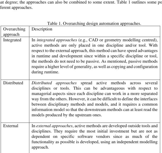
When multiple disciplines or computer tools (e.g., software) are involved, in a broad sense, three approaches for the scope and the placement of active methods are possible – integrated, distributed or external – with respect to the computer tools and/or the disciplines. Each approach has its advantages and disadvantages. Thus, the specifics of each context should decide which approach ought to be adopted and to what degree; the approaches can also be combined to some extent. Table 1 outlines some points about the different approaches.
Table 1. Overarching design automation approaches. Overarching
approach
Description
Integrated In integrated approaches (e.g., CAD or geometry modelling centred), active methods are only placed in one discipline and/or tool. With respect to the external approach, this method can have speed advantages in runtime and development since within a specific discipline or tool, the methods do not need to be passive. As mentioned, passive methods require a higher level of generality, as well as copying and configuration during runtime.
Distributed Distributed approaches spread active methods across several
disciplines or tools. This can be advantageous with respect to managerial aspects since each discipline can work in a more separated way from the others. However, it can be difficult to define the interfaces between disciplinary methods and models, and it requires a common information model so that the downstream methods can at least read the models produced by the upstream ones.
External In external approaches, active methods are developed outside tools and disciplines. They require the most initial investment but are not as dependent on specific software vendors since as much of the functionality as possible is developed, using an independent modelling approach.
Extension technique
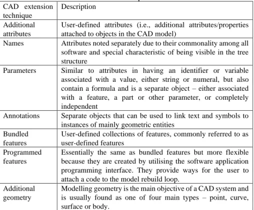
In previous research (T. Heikkinen et al., 2018), seven extension techniques were identified for CAD models, as follows: names, additional attributes, annotations, parameters, bundled features, programmed features and additional geometry (see Table 2 for their descriptions). In Case 1 above two additional extension techniques were identified: key-words and qualitative requirements (e.g. tangential inner faces of geometry).
Awareness of dependencies can help make manual development methods more efficient but are absolutely required if these are built into an automated method. A type of trade-off is possible between method generality and required extensions to the product model. Finding the correct features and perhaps, fixing issues with qualitative requirements (such as non-tangential inner faces) could be built into the methods by using for instance feature-recognition techniques and additional rules. However, this would require additional investment in time, and the methods’ complexity would drastically increase, which should be weighed against the actual return. Since the extensions required in one discipline may also restrict the other disciplines, either explicitly (e.g., the requirement to follow a naming convention) or implicitly (e.g., effects on modelling flexibility), it is important to agree that the extensions should be reasonable and not negatively affect the future development of either method.
Table 2. Extension techniques for CAD models. CAD extension
technique
Description Additional
attributes
User-defined attributes (i.e., additional attributes/properties attached to objects in the CAD model)
Names Attributes noted separately due to their commonality among all software and special characteristic of being visible in the tree structure
Parameters Similar to attributes in having an identifier or variable associated with a value, either string or numeral, but also contain a formula and is a separate object – either associated with a feature, a part or other parameter, or completely independent
Annotations Separate objects that can be used to link text and symbols to instances of mainly geometric entities
Bundled features
User-defined collections of features, commonly referred to as user-defined features
Programmed features
Essentially the same as bundled features but more flexible because they are created by utilising the software application programming interface. They provide ways for the user to attach a code to the model rebuild loop.
Additional geometry
Modelling geometry is the main objective of a CAD system and is usually found as one of four main types – point, curve, surface or body.
Many of these extension techniques are applicable to other models as well. For instance, spreadsheets can also be extended by using notes that are similar to CAD-model annotations or user-defined functions that are similar to programmed features. Three differences that can be identified among these extension techniques for CAD models are required additional aid, comprehensiveness and whether or not they can contain
executable information. These aspects should also be evaluated for each extension technique available in
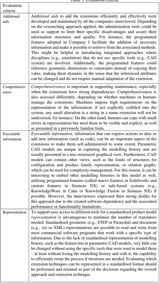
each model type, in addition to whether they can be represented in the desired formats. See Table 3 for clarity of each of evaluation criteria.
Table 3. Evaluation criteria. Evaluation
criteria
Additional aids
Additional aids to add the extensions efficiently and effectively were
developed and maintained by all the companies interviewed. Depending on the overarching approach applied, the administration tools could be used as support to limit their specific disadvantages and assure their information structures and quality. For instance, the programmed features adopted in Company I facilitate the addition of necessary information and make it possible to retrieve from the associated methods. This might be helpful in introducing integrated approaches where disciplines (e.g., simulation) that do not use specific tools (e.g., CAD system) are involved. Additionally, the programmed features could reference geometric dimensions or constraints instead of copying their value, making them dynamic in the sense that the referenced attributes can be changed and do not require manual adaptation of the extension.
Comprehensiv eness
Comprehensiveness is important in supporting maintenance, especially
when the extensions have strong dependencies. Comprehensiveness is also assessed differently, depending on whether machines or humans manage the extensions. Machines impose high requirements on the representation of the information; if not explicitly codified into the system, any small alteration to a string in a name extension will not be understood, for instance. On the other hand, humans can cope with small errors in representation but need them to be visible and explicit, as well as presented in a previously familiar form.
Executable information
Executable information, information that can express actions to alter or
add new information (such as code), can be an important aspect of the extensions to make them self-administered to some extent. Parametric CAD models are unique in capturing the modelling history and are usually presented in a tree-structured graphical view. Furthermore, CAD models can contain other views, such as the kinds of structures for configuration and product family representation, or relation graphs, which can be used for complexity management. For this reason, it can be interesting to embed other modelling histories in this model as well, utilising programmed features (called macro features in Solidworks and custom features in Siemens NX) or rule-based systems (e.g., KnowledgeWare in Catia or Knowledge Fusion in Siemens NX) if possible. However, the interviewees expressed their strong dislike for this approach due to the created software dependency and the associated performance or functionality limitations.
Representation To support easy access to different tools for a standardised product model
representation is advantageous to minimise the number of translators
needed. Standardised geometric (e.g., STEP or Parasolid) and document (e.g., .txt or XML) representations are possible to read and write from most commercial software programs that work with a specific type of information. Due to the lack of standardised representation of modelling history, such as the feature tree in parametric CAD models, very little can be changed without using the specific tools that were used to model them – at least without losing the modelling history and with it, the capability to efficiently rerun the process if iterations are needed. Evaluating which extension techniques can be represented in a standardised format should be performed and retained as part of the decisions regarding the overall approach and extension technique.
10 Conclusion
Extending product model constituents with process-related information to support an efficient and effective information exchange between and within disciplinary methods and models has been shown as a common industrial practice when realising automation systems. A conceptual framework named extended product model has been developed from executing an automation project and studying three Swedish industrial companies. It can be concluded that choosing extension techniques should be a conscious decision and could be based on the overarching design automation approach (integrated, distributed or external), the types of models (CAx-models, spreadsheet-models, etc.) and the weight on standardised model representations. By knowing which extension techniques are available, the dependencies on heterogeneous system items could be explored, and complexity could be assessed and perhaps controlled to some extent.
References
André, S. et al. (2017) ‘The design platform – a coherent platform description of heterogeneous design assets for suppliers of highly customised systems’, Journal of Engineering Design, Vol. 28 No. 10– 12, pp. 599–626. doi: 10.1080/09544828.2017.1376244.
Camba, J. et al. (2014) ‘Extended 3D annotations as a new mechanism to explicitly communicate
geometric design intent and increase CAD model reusability’, CAD Computer Aided Design, Vol. 57, pp. 61–73. doi: 10.1016/j.cad.2014.07.001.
Cees, B. (2015) ‘Multidisciplinary Design Optimization - Designed by Computers’, in Concurrent
Engineering in the 21st Century, pp. 421–454.
Chen, Y.-M. and Wei, C.-L. (1997) ‘Computer-aided feature-based design for net shape manufacturing’,
Computer Integrated Manufacturing Systems, Vol. 10 No. 2, pp. 147–164. doi:
http://dx.doi.org/10.1016/S0951-5240(97)00006-2.
Ding, L. et al. (2007) ‘An extended product model for constraint-based redesign applications’ in
Proceedings of ICED 2007, the 16th International Conference on Engineering Design
Ding, L., Davies, D. and McMahon, C. A. (2009) ‘The integration of lightweight representation and annotation for collaborative design representation’, Research in Engineering Design, Vol. 20 No. 3, pp. 185–200. doi: 10.1007/s00163-009-0077-2.
Elgh, F. (2007) Computer-Supported Design for Producibility: Principles and Models for System
Realisation and Utilisation, PhD. Thesis, Chalmers Univeristy of Technology, Sweden. Available at:
http://hj.diva-portal.org/smash/record.jsf?pid=diva2:34226.
Erixon, G. (1998) Modular function deployment: a method for product modularisation, PhD. Thesis, The Royal Institute of Technology, Sweden.
Fenves, S. J. et al. (2008) ‘CPM2: A core model for product data’, Journal of Computing and Information
Science in Engineering, Vol. 8 No. 1. doi: 10.1115/1.2830842.
Heikkinen, T., Johansson, J. and Elgh, F. (2017) ‘Extended CAD-Models – State of Practice Within Three Companies’ in IEEE International Conference on Industrial Engineering and Engineering
Management
Heikkinen, T., Johansson, J. and Elgh, F. (2018) ‘Review of CAD-model Capabilities and Restrictions for Multidisciplinary use’, Computer-Aided Design and Application, Vol. 15 No. 4, pp. 509– 519. doi: 10.1080/16864360.2017.1419639.
Heikkinen, T. M. D., Johansson, J. and Elgh, F. P. W. (2018) ‘Extended Design Assets Enabling Automated Tool Development As a Part of a Product Platform Approach’ in International Design
Conference, pp. 757–768. doi: 10.21278/idc.2018.0219.
Johansson, J. (2011) ‘How to Build Flexible Design Automation Systems for Manufacturability Analysis of the Draw Bending of Aluminum Profiles’, Journal of Manufacturing Science and Engineering, Vol. 133 No. 6, p. 061027. doi: 10.1115/1.4005355.
Johansson, J. (2017) ‘Analysing engineering knowledge in cad-models and spread sheets using graph theory and filtering’, Advances in Transdisciplinary Engineering, Vol. 5, pp. 629–638. doi: 10.3233/978-1-61499-779-5-629.
Johansson, J. and Elgh, F. (2017) ‘Automated design assessment as a strategic part of design platforms’ in
Advances in Transdisciplinary Engineering, pp. 441–448. doi: 10.3233/978-1-61499-779-5-441.
Lehtonen, T. et al. (2003) ‘Dynamic Modularisation - A challenge for design process and product architecture’, in 14th International Conference on Engineering Design. Available at: http://dspace.cc.tut.fi/dpub/handle/123456789/17525.
design environment’, International Journal of Agile Systems and Management, Vol. 8 No. 3-4, pp. 284–304. doi: 10.1504/IJASM.2015.073522
Lundin, M. et al. (2017) ‘Efficient Design Module Capture and Representation for Product Family Reuse’,
Journal of Computing and Information Science in Engineering, Vol. 17 No. 3, p. 031002. doi:
10.1115/1.4035673.
Lyu, G., Chu, X. and Xue, D. (2017) ‘Product modeling from knowledge, distributed computing and lifecycle perspectives: A literature review’, Computers in Industry, Vol. 84, pp. 1-13. doi: 10.1016/j.compind.2016.11.001.
Merriam Webster. [online] https://www.merriam-webster.com/dictionary/system (Accessed 14 February 2019).
Miller, A. M. et al. (2017) ‘Towards identifying the elements of a Minimum Information Model for use in a Model-Based Definition’ in ASME 2017 12th International Manufacturing Science and Engineering
Conference. doi: 10.1115/MSEC2017-2979.
Pakkanen, J., Juuti, T. and Lehtonen, T. (2016) ‘Brownfield Process: A method for modular product family development aiming for product configuration’, Design Studies, Vol. 45, pp. 210–241. doi:
10.1016/j.destud.2016.04.004.
Parasuraman, R., Sheridan, T. B. and Wickens, C. D. (2000) ‘A model for types and levels of human interaction with automation’, IEEE Transactions on Systems, Man, and Cybernetics Part A:Systems
and Humans, Vol. 30 No. 3, pp. 286–297. doi: 10.1109/3468.844354.
Robertson, D. and Ulrich, K. (1998) ‘Planning for Product Platforms’, Sloan Management Review, Vol. 39 No. 4, pp. 19–31.
Rocca, G. La (2012) ‘Knowledge based engineering: Between AI and CAD. Review of a language based technology to support engineering design’, Advanced Engineering Informatics Elsevier Ltd, Vol. 26 No. 2, pp. 159–179. doi: 10.1016/j.aei.2012.02.002.
Salomons, O. W., van Houten, F. J. A. M. and Kals, H. J. J. (1993) ‘Review of research in feature-based design’, Journal of Manufacturing Systems, Vol. 12 No.2.
Shooter, S. B. et al. (2000) ‘A Model for Information Flow in Design’ in Proceedings of DETC2000:
ASME International Design Engineering Technical Conferences, pp. 1–15.
Stokes, M. (2001) Managing Engineering Knowledge, London and Bury St Edmunds, United Kingdom. Trainer, A. et al. (2016) ‘Gaps Analysis of Integrating Product Design, Manufacturing, and Quality Data in
the Supply Chain Using Model-Based Defintion’ in ASME 2016 11th International Manufacturing
Science and Engineering Conference Virginia, pp. V002T05A003. doi:
10.1115/MSEC2016-8792.
Verhagen, C. (2013) An Ontology-Based Approach for Knowledge Lifecycle Management within Aircraft
Lifecycle Phases
Yang, W. Z. et al. (2008) ‘Recent development on product modelling: a review’, International Journal of