PROCESS CONTROL AND AUTOMATION OF A PU
MOULDING MACHINE
Muhammad Imran Khan (820512-P679)
Muhammad Junaid Atta (820811-P115)
THESIS WORK 201
2
PROCESS CONTROL AND AUTOMATION OF A PU
MOULDING MACHINE
PROCESSREGLERING OCH AUTOMATION AV EN
PU-GJUTNINGSMASKIN
Muhammad Imran Khan (820512-P679)
Muhammad Junaid Atta (820811-P115)
This thesis work is performed at School of Engineering, Jönköping University within the subject area Electrical engineering with a major in Embedded systems, This work is part of the university's Master's degree. The authors are responsible for the given opinions, conclusions and results.
Supervisor: Adam lagerberg Credit points: 30 ECTS points Date: February 3rd 2012
Abstract
This Thesis Involves the Automation and Control of PU moulding machine. Foam is made by a chemical reaction of ISO and Polyol , when they combined each other by the help of some agitator or with some mixing element, foam starts to grow which can shaped after.
Previously there were such companies for foam making moulding machines they designed low pressure machines, because of this foam quality were not good because of low agitation and penetration. This Project is based on the Improvement and enhancement of such moulding machines with high pressure up to 200 Bar.
Sammanfattning
Denna uppsats medför Automation and Control av PU gjutning maskin. Skum görs genom en kemisk reaktion av ISO och polyol, när de kombineras med varandra med hjälp av några agitator eller med viss blandning element, skum börjar växa som kan formas efter.
Tidigare fanns sådana bolag för skum gör gjutning maskiner de konstruerade lågt tryck maskiner, på grund av detta skum kvaliteten var inte bra på grund av låg agitation och penetration. Detta projekt baseras på förbättring och förstärkning av sådan gjutning maskiner med högt tryck upp till 200 bar.
Summary
Summary of this Masters Thesis report covers the Introduction and the background of Process Control and Automation of a PU Moulding Machine, designing and selection of new technique plus the simulation model which is an important part of our project in order to program the controller according to the new design and techniques. This report will also interpret the complete practical implementation of our design.
Acknowledgment
We would like to express our gratitude to all those who gave us the possibility to complete this thesis. We also want to thank the Department of Maintenance and Fabrication Master Enterprises for giving us permission to commence this thesis in the first instance, to do the necessary research work and to use departmental data. I have furthermore to thank the Assistant Professor Automatic control Computer and electrical engineering, School of Engineering, Mr. Adam Lagerberg, he provided us research experience throughout this project.
We are deeply indebted to my external supervisor Mr. Wahaj Mehdi from the Instrument and Control Department of JGC-DESCON whose help, stimulating suggestions and encouragement helped me in all the time of research for and writing of this thesis & closely at the final version of the thesis for English style and grammar, correcting both and offering suggestions for improvement.
By completing this project we gain valuable knowledge and information of control systems design in industrial machines including panel designing as well as plc programming. During our project we experienced many aspects of industrial automation and controls like using different kinds of sensors, transducers, and controllers.
We also gain the experience of handling different problems during the project like design problems and how to manage the schedule of machine fabrication. The main conclusion that we have observed in our thesis is that we use our educational knowledge practically because we did not get better chance before in our professional careers.
Especially, we would like to give our special thanks to our parents whose patient love enabled us to complete this work.
Table of Contents
1 Introduction... 1
1.1 Background ... 1
1.2 Purpose and Aims... 1
1.3 Outline... 2
1.4 Introduction to the Company... 2
2 Designing & selection of new technique ... 3
2.1 Mixing Head... 4
2.2 Pouring Process Procedure ... 5
2.3 Software Simulation ... 6
2.4 LP/HP Procedure Plot ... 7
2.5 Pouring Procedure in Production ... 8
2.6 Pouring Procedure in Production Plot ... 9
2.6.1 Conditions: ... 9
2.6.2 Definition of the Procedure Production Plot:... 9
2.6.3 Pouring Timer Set To A = 2 Sec. ...10
2.7 Proximity Error Procedure Module ...11
2.7.1 Conditions...11
2.8 Proximity Error Procedure Plot...12
2.9 Errors Procedure Matlab Modules ...13
2.9.1 Conditions...13
2.9.2 Air/Flow out of Range & Pressure Error Iso/Polyol Module ...13
2.9.3 Error ISO/Polyol Module Plot ...14
3 Selection Of Industrial Controller...15
3.1 PC’s...15 3.2 PAC’s ...16 3.3 PLC ...16 3.4 Mitsubishi PLC FX2NC...17 3.5 Mitsubishi PLC Features...17 3.5.1 Base Units FX2NC ...17 3.5.2 Features...18
4 Main Parts of Machine ...19
4.1 Flow Control ...19
4.2 Overall Machine Control ...20
4.3 HMI Descritption ...21
5 Implementation ...23
5.1 Flow Diagram ...23
5.2 Flow Diagram Description...24
5.2.1 Liquid Flow ...24
5.2.2 Tanks ...25
5.2.3 Heat Exchanger and Pumps ...26
5.2.4 Motors...27 5.2.5 Inverters...27 5.3 Basic PLC operation ...28 5.3.1 Evaluation of Basic PLC ...28 5.3.2 Advantages of PLC...29 5.3.3 Flexibility ...29
5.4 Implementation Changes and Error Correction...29
5.4.1 Large number of Contacts ...29
5.4.2 Lower Cost ...30
5.4.3 Speed of operation ...30
5.4.4 Security...30
5.4.5 Ease of Changing by Program ...30
5.4.6 Disadvantages of PLC’s ...30
5.4.7 Newer Technology ...30
5.4.8 Fixed Program Application...30
5.4.9 Ladder and Boolean Programming Mode...31
5.5 AC Motors ...31 5.5.1 Introduction ...31 5.5.2 AC motor Construction...31 5.5.3 Stator Construction ...31 5.5.4 Stator Windings ...32 5.6 Flow Sensor...32
5.6.1 Selection of flow meters: ...33
5.6.2 Construction And Internal Parts Of Flow meter ...33
5.7 Pressure Gauge ...34 5.8 Proximity Sensor ...34 5.9 Temperature Controller ...35 5.10 Air Switches...36 5.11 HMI ...36 6 Results...37
7 Conclusions and Discussions ...38
8 References...39
9 Appendix 1...40
9.1 Electrical Wiring Diagrams Of machine...40
9.1.1 FX 2NC base unit wiring diagram ...40
9.1.2 FX2NC Input Extension Module Wiring Diagram...41
9.1.3 FX2NC Output Extension Module Wiring Diagram ...41
9.3 Inverter Data Sheet ...43
9.4 Positive Displacement Flow Sensors...45
9.5 REXROTH Pressure Gauge ...47
9.5.1 Specifications...47
10 Appendix 2 (PLC Program) ...1 to 2 11 Appendix 3 (Instructions List) ...1 to 2 12 Appendix 4 ( PLC Details) ...1 to 2 13 Appendix 5 (IO Details) ...1 to 2 14 Appendix 6 (Timer Counter Values) ...1 to 2
List of Figures
Figure 2.1 Mixing head... 4
Figure 2.2 Pouring process ... 5
Figure 2.3 Matlab Model ... 6
Figure 2.4 Simulink Plot... 7
Figure 2.5 Matlab Pouring Procedure Model ... 8
Figure 2.6 Simulink Pouring Procedure Plot With 2sec ... 10
Figure 2.7 Proximity Sensor Error Model ... 11
Figure 2.8 Proximity Sensor Error Plot ... 12
Figure 2.9 Matlab Air / Flow out of range & pressure Error Model ... 13
Figure 2.10 Simulink Error Plots... 14
Figure 3.1 Mitsubishi Plc ( Fx2nc Base Unit ) ... 17
Figure 4.1 Flow Control Diagram... 19
Figure 4.2 Overall Machine Control Diagram... 20
Figure 4.3 Hmi Options Diagram ... 21
Figure 4.4 Pouring Panel Diagram... 22
Figure 5.1 Process Flow Diagram... 23
Figure 5.2 Liquid Flow Diagram ... 24
Figure 5.3 Tanks ... 25
1 Introduction
In electronics there are too many fields that can motivate our concentration towards them but deciding one depends on our enthusiasm. Our intentions were always towards automation that is why we were convinced to use Programmable Logic Controller as a control device.
This Project is concerned about how to mix two different types of chemicals in some desired ratio as well as tricks to handle and manipulate and use data from different electro pneumatic, flow, level, pressure, temperature sensors and pneumatic actuators to develop logic in PLC, to perform different tasks as per process requirement.
1.1 Background
Master Enterprises has always been at the forefront as an integral component in the industrialization of country's economy. 1988 saw the foundation of the Procon Engineering which rapidly grew to be a totally self-reliant composite manufacturing facility in an area of 48,007 square meters that currently manufactures.
Today , Procon the sister company of Master Enterprises supplies finished products of high quality to car ,truck, bus, motorcycle, pickup & tractor manufacturers like Suzuki, Toyota, Honda, Nissan, Hyundai, Kia Motors, Daihatsu, Hino, Nissan Diesel, Volvo, Honda Motorcycle, Yamaha Motorcycle, Suzuki Motorcycle, Millat Tractor, Al-Ghazi Tractor.
Moreover, Procon has the distinguished honour of exporting sports car seats to USA, Europe & Asia. With the ability to produce 200,000 seats per annum on a single shift basis, Procon has the capability to fulfil any requirements for car seats or interior.
1.2 Purpose and Aims
In the old low pressure PU moulding machine the main problem was to maintain the ratio and also to change the ratios of both the chemicals according to the desired products. But in the old machine the ratio was fixed for both the chemicals, in order to change the ratio they added variable frequency drives to solve the problem but this does not affects the performance of the machine as far as the production department is concerned.
That was the reason behind the development and manufacturing of High Pressure Moulding Machine, which can reduce production loss, increase production rate with lesser errors and better accuracy.
1.3 Outline
This report is structured on the basis of the Simulation designing of the pouring procedures its results in Matlab and Simulink, hardware description, its application and implementation.
Hardware is described by using flow of simulation software, and the complete description of software design and simulation using Matlab.
1.4 Introduction to the Company
Master Enterprises has always been at the forefront as an Integral component in the industrialisation of country’s economy.
Master Group of Industries
Master Enterprises (Pvt)
Ltd. 1963 Karachi
PU foam for mattresses, sofas, pillows, cushions, Automobile seats, spring Mattresses, Office Chair.
Master Chemical (Pvt) Ltd 1984 Karachi
Chemical systems formulation PU - Rigid Insulation spray for home, Industry, Cold Storage, Fishing Boats (Fish hold). Durafoam (Pvt) Ltd. 1988 Lahore
Procon Engineering (Pvt)
Ltd 1988 Karachi
Complete car interiors & Other automobile Components Master Polymer Industries
Ltd 1989 Peshawar
Manufacture of PU foam for Mattresses, sofas, pillows & cushions for the Northern region. Master Textile Mills Ltd.. 1992 Lahore Production of fabric and Garments for export to Europe and USA Master Auto Engineering
(Pvt) Ltd 1996 Lahore
Manufacture of PU foam for Automobile seats, spring
Mattresses for the Punjab region. Master Foam (Pvt) Ltd. 1998 Kashmir
Manufacture of PU foam for Mattresses, sofas, pillows & cushions for the Northern region.
2 Designing & selection of new technique
By studying different kinds of methods to control and vary the ratios of different liquids we find that the mixing will always be false or the ratios will always vary when one uses the old technique of mixing at low pressure using simply a mixing head.
Then we find that if we want the accuracy of mixing of the liquids we can use a mixing head for high pressure that is we must have to control the process of mixing by an injection head and controlling it by a machine controller. In order to control the mixing pressure we must have to simulate the process of mixing head according to the desired requirements of machine.
The desired requirements of the machines are to maintain the Hydraulic pressure and the Air pressure constant through out the production process of the pouring mixing head. So in this regard we have to design a control method for the mixing head which will work correctly in the machines functionality.
Thus first we have simulated and designed the process of the mixing head as far as the production process is concerned using the MATLAB and SIMULINK models. And then we implemented the process in the machine controller.
The second big thing for us is to select the controller that is which controller is the best for our project and what are the advantages and disadvantages of that specific industrial controller over the others as far as this project is concerned.
First we will define the MATLAB and SIMULINK models in details and briefly describe them according to the design of the mixing process and the production processes with the addition of different errors.
After that we will explain in detail about the different parts of the machine individually and briefly.
2.1 Mixing Head
The controlling of the mixing head and all its features during production and working will also be controlled by the controller.
Figure 2.1 Mixing head
The injection head of the PU-moulding machine is the main part and the heart of machine and is consist of two basic parts the CLEANING SHAFT and the POURING
SHAFT,the cleaning shaft as its name explains that is used for the cleaning of the head
during the production shot whenever the shot is taken , and the pouring shaft is used for the opening of pouring piston respectively .
Basically it’s the pouring shaft that we used as are main idea by varying the time of its opening using the pouring timer that can be entered from the HMI through PLC timer defined in the PLC controller.
The delay timers and the pouring timers are different for each choice, you can enter up to 30 choices With 30 different timers separately from the HMI.
The injection moulding head is the main part of the machine as it has to be controlled through the programmable logic controller. The injection moulding head procedure is being simulated on the MATLAB and SIMULINK by designing the model for its procedure before writing the program for the PLC and the HMI. It is very important for our thesis as we have to first design the model and then implement it in the controller and into the machine.
In the next section we will define the basic procedure of the pouring process for the injection moulding head in detail.
2.2 Pouring Process Procedure
Starting point Transition state of processHMI input data
Delay timer starts
HMI input data
User defined
Figure 2.2 Pouring process Pouring button on pouring panel Machine goes to high pressure from low pressure Recycle timer After completing recycle time cleaning shaft valve goes high Pouring shaft valve opens After completing pouring machine Pouring timer As proximity sensor sends signal to controller Delay timer
2.3 Software Simulation
Simulation is made on Matlab, its soft copy is also attached with report. First we will define the matlab module for LP/HP PROCEDURE .
Figure 2.3 Matlab Model
When Pouring From HMI Is Off And The Pouring Button Is Pressed From The Pouring Panel The Machine Goes To High Pressure From Low Pressure. As Shown In The Plot Below.
POURING OFF FROM HMI
2.4 LP/HP Procedure Plot
Whenever the pouring button is pressed from the pouring panel and the pouring is disabled from the HMI the IP/HP valves goes to high state and no other valve opens at that instant , this procedure is only used for setting the machine parameters like ratio, flow and timer values for the production.
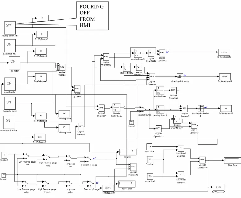
2.5 Pouring Procedure in Production
The pouring procedure module of matlab is given below in which no error occurs and the production shot timer is set to (a = 2sec). All the motors are in ON states, pouring is enabled from the HMI, and then the pouring button is pressed from the pouring panel respectively.
Figure 2.5 Matlab Pouring Procedure Model POURING
ON FROM HMI
2.6 Pouring Procedure in Production Plot
2.6.1 Conditions:
- When Pouring Timer Is Set To A = 2sec - All the Motors Are Running Smoothly - Pouring Is Enabled From the HMI - No Errors
- And Pouring Button Is Pressed From the Pouring Panel, - Then The Plot Shown Below Occurs.
2.6.2 Definition of the Procedure Production Plot:
1. As the pouring button is pressed machine goes to high pressure immediately. 2. After 1sec the cleaning shaft operating valve goes to high
3. And as the proximity sensor senses the cleaning shaft the pouring piston opens after the delay of 2sec
4. And after the delay of 2sec the pouring piston operating valve goes high for the time given by the users, in this case it set to 2sec
5. After completing the desired time for the production shot the pouring piston operating valve goes OFF
6. And then after the lower transition of the pouring piston operating valve the delay occurs of about 1sec after which the cleaning shaft operating valve goes into its OFF state
7. And as the cleaning shaft operating valve goes to its OFF state the machine goes to low pressure from high pressure after 1 sec delay.
All this procedure runs only if the above mentioned conditions fulfilled by operators during the production.
2.6.3 Pouring Timer Set To A = 2 Sec.
2.7 Proximity Error Procedure Module
2.7.1 Conditions
- When All The Motors Are In On State - Pouring Is Enabled From the HMI - Priximity Sensor Is Faulty
- And Then The Pouring Button Is Pressed From The Pouring Panel.
Figure 2.7 Proximity Sensor Error Model
Proximity Sensor
2.8 Proximity Error Procedure Plot
Whenever the proximity sensor that senses the cleaning shaft goes faulty the machine goes to HIGH PRESSURE, cleaning shaft opens after 1sec delay and turns off automatically if not sensed by the sensor within the specified time of 2 sec, and after the delay of 6sec the machine goes to low pressure, and results in no pouring output. An error occurs on the screen as well showing that the sensor is faulty.
2.9 Errors Procedure Matlab Modules
2.9.1 Conditions
Whenever air switches, pressure sensors goes low error comes & machine goes to low pressure and no production shot occurs.
2.9.2 Air/Flow out of Range & Pressure Error Iso/Polyol Module
Figure 2.9 Matlab Air / Flow out of range & pressure Error Model
AIR SENSOR ISO Flow Out Of Range High Pressure Iso/
2.9.3 Error ISO/Polyol Module Plot
Whenever these errors occurs all the machine goes down on low transition states like the cleaning shaft goes off , pouring shaft goes off , and lp/hp valve goes off as well , and also indicating that which error occurs on the screen of the HMI .
3 Selection Of Industrial Controller
In order to select the industrial controller we must study different kinds of controllers like PC’s , PAC’s (Programmable Automation Controller) and the PLC’s.
3.1 PC’s
Many engineers uses PCs for industrial control because the PC’s provides software capabilities for advanced tasks, offers a graphical, rich development and user environments, and uses commercial off-the-shelf (COTS) components.
The PC also delivers unparalleled flexibility, highly productive software, and advanced low-cost hardware
But in our project the tasks need not an industrial PC because of the nature and the functional requirements are concerned.
We don’t have to show a graphical representations of the machine as in the P AND I D diagrams for our project on the HMI, we just deals with the settings of the machine and the ratio and flow control quantities respectively.
PCs are not very much ideal for control applications. Although they are still used when dealing with the advanced functionality such as analog control and simulations, database connectivity, Web-based functionality, and communication with third-party devices, the PCs fail in one key industrial aspect: standard PCs are not designed for rugged environments.
Lack of rugged design presents three challenges for PCs in industrial settings
1. In the industrial environments, where hourly downtime is often measured in thousands or even millions of dollars lost per hour, the PC's general-purpose OP systems has experienced system crashes and unplanned rebooting that can make it a risky choice for control
2. With the majority of computer hardware sources serving the consumer market, many standard PC components cannot withstand the often harsh conditions in an industrial setting.
3. The PC has presented automation engineers with a complex and unfamiliar programming environment. Plant operators need the ability to override a system for maintenance or troubleshooting.
3.2 PAC’s
The industrial PC’s sector has expanded and improved very much in recent years, but the PC’s are still a challenging platform for many industrial automation applications.
Some engineers uses these new systems with more rugged hardware and special purpose operating systems, they face the task of emerging together a system that has the reliability of a PLC and the added functionality the PC provides.
PAC’s are basically used for large plants according to the desired requirements and capabilities. In PAC’s different controllers are used for the controlling of more complex architectures.
The PAC, due to its flexibility, power, and reliable hardware and software, is quickly becoming the ultimate solution for complex industrial control applications.
We don’t have the requirements of a large and more complex control system in the project and we also have to look after the cost management tools which we cannot go just by using PAC’s in the project.
3.3 PLC
Choosing the right hardware for industrial and control applications is not an easy task for us in order to resolve this issue [1].
Because we meet so many industrial application challenges with traditional PLC solutions, there is a strong demand for simple low-cost PLCs.
Industrial applications need to incorporate integrated hardwares and softwares as well and offer a short time to market; and will also be highly reliable, powerful and flexible, low cost, and easy to maintain and upgrade.
The PLC has been the automation solution of choice for industrial control engineers. Familiar and reliable, the PLC has evolved to incorporate analog I/O, network communication, and new programming standards.
With PLCs one can manually force coils to desired states and quickly patch the affected code to override a system saving the time. But with PC operating control systems, operators and engineers are required to learn new and more advanced tools.
The PLC has not traditionally delivered viable solutions for applications that required higher loop rates, advanced control systems algorithms, more analog I/O capabilities, and better integration with an enterprise communication networks.
3.4 Mitsubishi PLC FX2NC
We have used the MITSUBISHI FX2NC series PLC in our project due to its flexibility and performance with the high speed counters we used for calculating the flow meter pulses for the measurement of the flow, and its ability to work accurately under hazardous areas in the industry. [8]
We also used extended blocks with the base unit for more i/o due to the requirements of the project and also used analogue module for the controlling of the inverters respectively in the lower section we also explains in detail about the function and controlling methods for the PLC in general for the readers to easily understand the project.
Programmable Logic Controllers (PLCs), also referred to as programmable controllers, are in the computer family. They are used in commercial and industrial applications. A PLC monitors inputs, makes decisions based on its program, and controls outputs to automate a process or machine. This course is meant to supply you with basic information on the functions and configurations of PLCs.
Figure 3.1 Mitsubishi Plc ( Fx2nc Base Unit )
3.5 Mitsubishi PLC Features
3.5.1 Base Units FX2NC
The base units of the FX2NC are available in versions with 16, 32, 64 or 96 I/Os. Nine output types are available: eight different transistor output types and one relay output type.
3.5.2 Features
1 Very compact dimensions
2 Standard programming unit interface
3 LEDs for indicating the input and output status
4 Removable terminal blocks (screw terminals for the relay output type) or ribbon cable connectors
(for the transistor output types) for system cabling
5 Slot for memory boards for up to 16 k steps PLC program
6 Adapter modules and system cabling sets available for units with ribbon cable connectors
- Why we use a MITSUBISHI PLC rather than any other manufacturers like SIEMENS, ALLENBRADLLEY, OMRON or SCHENIDER ?
We use MITSUBISHI PLC industrial controller in our project due to some basic reasons like flexibility, speed, dimensions and the most important is the cost. Further the comparison for the Mitsubishi Plc with the other manufacturers is listed below.
Manufacturer Program capacity
Data Capacity
Built in I/O
Points Scan Time
Accuracy @ Ambiant
Temp
Dimensions Mitsubishi
FX2N 8K steps 32K steps 16 DI/DO <0.2 Sec +-0.1% 35X85 mm Omron
CJ1W-AD081-V1 30K steps 64K steps None <0.27 Sec +-0.2% 62mm Fatek
FBs-40MBT
Flash
/SRAM 20K steps 12 DI/DO <0.35 Sec +-0.1% 90X60mm Modicon
140CPU11302 8K 2K None 5ms/k +-0.2% 39.4X266X203mm
Siemens
4 Main Parts of Machine
This flow illustrates the main parts of the machine using flow diagram parts of the machine consist of two main parts, one is flow control and another is overall flow control of the system.
4.1 Flow Control
FLOWMETER SENSORS AC MOTORS
PRESSURE SENSORS RPM-CONTROL
AIR SWITCHES ACTUATORS
PROXIMITY SENSORS HYDRAULIC PUMP
TANK LEVEL SENSORS
Figure 4.1 Flow Control Diagram PU MOULDING M/C CONTROLLER HMI TOUCH PANEL DISPLAY (USER I/P)
4.2 Overall Machine Control
All the inputs and the outputs used for the machine controller including the sensors and the switches plus valves are displayed below in order to understand the interfacing method used in our technique.
POURING PANEL ERROR INDICATOR
HIGH PRESSURE/ HP/LP VALVES
LOW PRESSURE I/P
PROXIMITY SENSOR TIMERS+COUNTERS
COMPLETE
POURING PROCESS
FOR PRODUCTION
Figure 4.2 Overall Machine Control Diagram PU MOULDING M/C CONTROLLER HMI TOUCH PANEL DISPLAY (USER I/P)
4.3 HMI Descritption
All the options of the HMI are represented in the figure below which can be entered and monitored by the operator through out the production and setting time.
Every option shown in the diagram has its own seperate screen in the HMI program we designed for the machine.
Figure 4.3 Hmi Options Diagram HMI TOUCH PANEL DISPLAY (USER I/P) 1. PRODUCTION DATA 2. WORK DATA 3. CALIBERATION DATA 4. MACHINE DATA 5. MOTORS ON/OFF 6. MOTORS POSITIONERS 7. HYDRAULIC PUMP 8. SPECIFIC GRAVITY 9. 30 DIFFERENT CHOICES FOR 30 DIFFERENT PRODUCTION SHOTS 10. ERROR DISPLAYS 11. PRESSURE INDICATION FOR ERRORS 12. AIR PRESSURE INDICATION FOR ERROS 13. HP/LP INDICATION FOR PRODUCTION 14. TANK LEVEL SENSOR INDICATION 15. WEIGHT OF OUTPUT IN GM 16. ACTUAL FLOW OF BOTH THE CHEMICALS IN GM/SEC 17. ACTUAL RATIOS OF BOTH THE CHEMICALS 18. TIMERS SET FOR 30 CHOICES PLUS CHOICE NUMBERS
4.4 Pouring Panel
The figure shown below is the pouring panel used for our project includes the pouring button for pouring start/stop and the keypad for the changing of the number of choices with different ratios and timers.
Keypad used in the pouring panel will give the output in the binary format for 6 bits converting it into 30 choices ranging from 0-29 choices each have a seperate timer value , different ratio and thus different total output weight in grams.
Figure 4.4 Pouring Panel Diagram
PU MOULDING M/C
CONTROLLER (FX 2NC PLC)
5 Implementation
Process can be represented by using flow diagram, in order to understand the whole mechanism for PU moulding machine figure 5.1 is a flow diagram for one liquid chemical line.
5.1 Flow Diagram
5.2 Flow Diagram Description
5.2.1 Liquid Flow
The liquid flow starts from the tank passed through the air filter in order to filter the chemical before passing from the pumps and the head. From the air filters the chemical then pass from the pump for pressure that will be adjustable from the gauge mounted on the pump.
After passing from the pump the chemical then enters the flow meter zone which we use to count and display the actual flow of the chemical in our plc program.
The flow of both the liquids does not varies during the opening and closing of the head main shaft.
After passing from the flow meter zone the chemical has two directions to flow through, one is the recirculation direction and second is the head direction as shown in the figure above. This is the complete description of the flow diagram of the new PU moulding machine as far as flow of both the chemicals in each side is concerned.
Now we will explain each part step by step explaining the instruments and sensors functions plus their specifications as well.
5.2.2 Tanks
Starting from the tanks as each chemical has only one tank for storing the chemicals during production cycle. Each tank has a pneumatic control refilling pump for automatically filling the tanks. Each tank is also equipped with two level sensors for the indication of levels and for the refilling pumps. Tanks have a water flow jacket outside its base in order to control the temperature of the chemicals with in the tanks as shown in the figure below.
The temperature of both the tanks are controlled by using individual traditional temperature controllers which is feasible for our application where RTD was used as a temperature element as RTD card for PLC was costly as compared to traditional temperature controllers.
Water flow in moulding tanks for temperature controlling of chemicals with in the tanks. The flow of cold water starts automatically through the jackets of the tanks when the temperature rises from the given set temperature in degree Celsius scale.
This will be controlled by using a temperature sensor PT100 for each tank and a temperature controller that enables the output to the 220vac solenoid valves controlled directly from the temperature controllers.
5.2.3 Heat Exchanger and Pumps
A single heat exchanger is used with each line of chemicals in order to control the temperature of chemicals during the chemical flow.
A single pump is used for each chemical in order to produce pressure mounted directly to the ac motors shaft as shown in the figure.
5.2.4 Motors
AC motors are used to drive the pumps for both the chemicals individually using inverters. Inverters are useful for controlling the flow and ratios of the chemicals during production process.
As we use them as VFD (variable frequency drives) and change the rpm of motors in order to change the flow of chemicals directly from the plc.
The plc will control the inverters rpm and will vary its output according to the input data entered from the HMI thus achieving the goal of variable ratio output which was not present in the old moulding machines.
We use SEW INVERTERS to drive the three phase ac motors for each chemical. Thus in order to drive the inverters we must need an analogue output module for controlling and varying the rpm of motors.
The voltage range from the analog output block varies from 0-10vdc and entered into the inverters variable speed reference inputs for controlling the motors accordingly.
5.2.5 Inverters
We use SEW inverters for driving the motors in VFC MODE .The inverters can vary their rpm by using PLC analogue block by providing them an analogue voltage range from 0-10vdc.
Figure 5.3 Interfacing Plc With Inverters FX 2N C FX 2N -2D A M D X 61B-SEW
We use 3 phase 15 KW , 1460 rpm , 400 v delta , 27.96 A motors for isocynate and 3 phase 17 KW , 1752 rpm , 440 v delta , 28.17 A motors for polyol sides. The above mentioned parameters gives the complete details of motors used for our machine.
5.3 Basic PLC operation
PLCs consist of input modules or points, a Central Processing Unit (CPU), and output modules or points. Input accepts a variety of digital or analogue signals from various field devices (sensors) and converts them into a logic signal that can be used by the CPU. The CPU makes decisions and executes control instructions based on program instructions in memory. Output
modules convert control instructions from the CPU into a digital or analogue signal that can be used to control various field devices (actuators). A programming device is used to input the desired instructions. These instructions determine what the PLC will do for a specific input [1].
An operator interface device allows process information to be displayed and new control parameters to be entered.
Pushbuttons (sensors), in this simple example, connected to PLC inputs, can be used to start and stop a motor connected to a PLC through a motor starter (actuator).
5.3.1 Evaluation of Basic PLC
The first PLC system evolved from conventional computers in the late 1960s and early 1970s. These first PLCs were mostly installed in automotive plants. Traditionally, the auto plants had to be shut down for up to a month at model changes over time.
The early PLCs were used along with other new automation techniques to shorten the changeover time.
One of the major time consuming changeover procedures had been the wiring of new or revised relay and control panels. The PLC keyboard reprogramming procedure replaced the rewiring of a panel full of wires, relays, timers, and other components.
The new PLC helped reduce reprogramming time to a matter of a new of a few days. In the 1980s, with more computer power per dollar available, the PLC came into exponentially increasing use. Some large electronics and computer companies and some
diverse corporate electronics divisions found that the PLC had become their greatest volume product.
The market for PLCs grew from a volume $80 million in 1978, to $1 billion dollars per year by 1990 and is still growing. Even the machine tool industry, where computer numerical controls have been used in the pst, is using PLCs.
PLC are also used extensively in building energy and security control systems. Other non-traditional uses of PLCs, such as in the home and in medical equipment, will be increasing n the 1990s.
5.3.2 Advantages of PLC
The following are some of the major advantages of using a programmable controller [1].
5.3.3 Flexibility
In the past, each different electronically controlled production machine required its own controller; 15 machine might require 15 different controllers. Now, it is possible to use just one model of a PLC to run any one of the 15 machines.
Furthermore, you would probably need less than 15 controller, because one PLC can easily run many machines. Each of the 15 machines under PLC control would have its own distinct program.
5.4 Implementation Changes and Error Correction
With the wired relay type panel, any program alteration requires time for rewiring of panels and devices. When a PLC program circuit or sequence design changes is made, the PLC program can be changed from the keyboard sequence in a matter of minutes.
No rewiring is required PLC controlled system. Also, if a program error has to be corrected in a PLC control ladder diagram, a change can be typed in quickly.
5.4.1 Large number of Contacts
The PLC has a large number of contacts for each coil available in its programming. Suppose that a panel wired relay has four contacts and all are in use when a design change requiring three more contact is made. It would mean that time must be taken to procure and install a new relay or relay contact block.
Using a PLC, however, would only require that three more contacts be typed in. the three contacts would be automatically available in the PLC.
5.4.2 Lower Cost
Increased technology makes its possible to compact more functions into smaller and less expensive packages. In the 1990s you can purchase a PLC with numerous relays, timers, counters, a sequencer, and other functions for a few hundred dollars.
5.4.3 Speed of operation
Relay can take a unacceptable amount of time to actuate. The operational speed for the PLC program is very fast. The speed for the PLC logic operation is determined by the scan time, which is s matter of milliseconds.
5.4.4 Security
A PLC program change can not be made unless the PLC is properly unlocked and programmed. Relay panels tends to undergo undocumented changes. People on the late shift do not always record panel alterations made when the office area is locked up for the night.
5.4.5 Ease of Changing by Program
Since the PLC can be reprogrammed quickly, mixed production processing can be accomplished. For example, if part B comes down the assembly line while part A is still being processed, a program fro part B’s processing can be reprogrammed into the production machinery in a matter of seconds.
5.4.6 Disadvantages of PLC’s
Following are some of the disadvantages of, or perhaps precautions for, using PLCs:
5.4.7 Newer Technology
It is difficult to change some personnel’s thinking from ladder and relays to the PLC computer concepts.
5.4.8 Fixed Program Application
Some applications are single function applications. It does not pay to use a PLC that includes multiple programming capabilities if they are not needed. One example is in the use of drum controller/sequencers. Some equipment manufacturers still use mechanical
drums with pages at an overall cost advantage. Their operational sequence is seldom or never changed, so the reprogramming available with the PLC would not be necessary.
5.4.9 Ladder and Boolean Programming Mode
An electrician and technician can accomplish the PLC programming in the ladder mode. Alternately, a PLC programmer who works in digital or Boolean control system can also easily perform PLC programming.
Plc’s normally have the LADDAR, FBD and STL programming languages.
5.5 AC Motors
5.5.1 Introduction
There are two ac motors used in our project one for ISO one for Polyol in order to control the flow using the Ac inverters that’s why we explained the complete structure of the motors below so that the reader will get some background of the motors and can easily understand the functionality of the machine.
5.5.2 AC motor Construction
AC induction motors are commonly used in industrial applications. The following motor discussion will centre around three-phase, 460 VAC, asynchronous, induction motors.
An Asynchronous motor is a type of motor where the speed of the rotor is other than the speed of the rotating magnetic field. This type of motor is illustrated below. The three basic parts of an AC motor are the rotor, stator, and enclosure.
5.5.3 Stator Construction
The stator and the rotor are electrical circuits that perform as electromagnets. The stator is the stationary electrical part of the motor. The stator core of a NEMA motor is made up of several hundred thin laminations.
5.5.4 Stator Windings
Stator laminations are stacked together forming a hollow cylinder. Coils of insulated wire are inserted into slots of the stator core. Each grouping of coils, together with the steel core it surrounds, form an electromagnet. Electromagnetism is the principle behind motor operation. The stator windings are connected directly to the power source.
Rotor Construction
The rotor is the rotating part of the electromagnetic circuit. The most common type of rotor is the “squirrel cage” rotor. Other types of rotor construction will be mentioned later in the course.
The construction of the squirrel cage rotor is reminiscent of rotating exercise wheels found in cages of pet rodents.
The rotor consists of a stack of steel laminations with evenly spaced conductor bars around the circumference.
The laminations are stacked together to form a rotor core. Aluminum is die cast in the slots of the rotor core to form a series of conductors around the perimeter of the rotor. Current flow through the conductors from the electromagnet. The conductor bars are mechanically and electrically connected with end rings. The rotor core mounts on a steel shaft to form a rotor assembly.
5.6 Flow Sensor
A flow meter is a device that meters movement of fluid in a conduit or an open space. This fluid could be water, chemicals, air, gas, steam or solids [7] [3].
In Controls and automation, and in a process flow is the basic need to maintain good process values, to measure flow there are so many techniques, and different types of instruments available, for field measurements local meters are available and for remote monitoring some special types of transmitters for display and monitor flow on some control circuit. Flow can be different types like liquid flow, gas flow and so on.
We select a local indicator as we don’t need to display pressure on our control circuit, this is basically a flow switch which can cut off the line on low and on high set points.
5.6.1 Selection of flow meters:
Selecting a flow meter can be an easy or a difficult task depending on the requirements. It is important to remember that there is no universal flow meter that will be appropriate for every application.
The selection process can be driven by many factors. Here we will list some of them 1. Accuracy requirements in the particular application
2. Repeatability requirements in the particular application 3. Price /economic constraints
4. Personal or company preference 5. Brand preference
6. Robustness or ability to work in harsh or hazardous type conditions 7. Size
8. Ease of installation 9. Longevity
5.6.2 Construction And Internal Parts Of Flow meter
Figure 5.4 Flow Meter Construction 1 Housing bottom 2 Housing cover 3 Gear wheels 4 Pre-amplifier 5 Connection plug 6 Pick-offs
SIKA positive displacement flow sensors are highly ac-curate transmitters that measure volume flows. They work on the positive displacement principle. The flowing medium causes a pair of gear wheels to rotate.
The sensor is manufactured to the highest accuracy and is then precisely assembled. The rotation is scanned by two non-contact pick-offs.
As each tooth generates a pulse, the resolution is very high. Very low flow rates can be accurately measured and small volumes can be dosed.
5.7 Pressure Gauge
We used pressure gauges for each ISO, POLYOL HYDRALIC pressures in order to show the operator the pressures at high values and to maintain the accuracy of the machine according to the settings organized for each production shot [4].
At high pressure the pressure should be within 150-200 bars for accurate mixing purpose. To measure pressure several techniques and instruments are
available. Some of them are as under. 1. Bourden tube
2. Bellous types instruments 3. Diaphragam
4. Strain gauge type 5. piezo electric type
6. Other electrical effects (capacitive, inductive)
The simplest way to measure pressure is a local indicator we use this type of instrument with two output digital signals one for high pressure and one for low pressure, pressure is measured by bourden tube type local indicator.
5.8 Proximity Sensor
We used proximity sensor in order to sense the cleaning shaft operations during the production shot, it was used to avoid errors and as well as the accidents [4]. A Proximity sensor can detect objects without physical contact. A proximity sensor often emits an electromagnetic field or beam and look for changes in the field.
The object being sensed is often referred to as the proximity sensor's target. Different proximity sensor targets demand different sensors. For example, a capacitive or photoelectric sensor might be suitable for a plastic target; an inductive proximity sensor requires a metal target.
5.9 Temperature Controller
Temperature controllers are needed in any situation requiring a given temperature be kept stable. This can be in a situation where an object is required to be heated, cooled or both and to remain at the target temperature (setpoint), regardless of the changing environment around it. There are two fundamental types of temperature control; open loop and closed loop control [5].
Open loop is the most basic form and applies continuous heating/cooling with no regard for the actual temperature output [9] [3].
In our thesis project we did not interface the temperature controller with the PLC as we don’t have to achieve that kind of accuracy plus if we do interface it with PLC we must use an extra temperature module with the PLC which will automatically increases our cost budget.
Figure 5.5 Open Loop Temperature Control
Closed loop control is far more sophisticated than open loop. In a closed loop application, the output temperature is constantly measured and adjusted to maintain a constant output at the desired temperature. Closed loop control is always conscious of the output signal and will feed this back into the control process [2].
Closed loop control is analogous to a car with internal climate control. If you set the car temperature to 75°, the climate control will automatically adjust the heating (during cold days) or cooling (during warm days) as required to maintain the target temperature of 75°.
5.10 Air Switches
For high speed switching of the valves we must maintain the air pressure of the machine in order to maintain the output weight and false output. The air pressure should be maintained between the range of about 5-6 bars.
These valves are used to move the mechanical parts of the mixing head during working in production and in calibration respectively.
5.11 HMI
All the parameters and flow meter readings was displayed on the HMI screen, a user can select 30 different choices which is pre installed in the controller and can select desired selection easily. We have used F930 GOT in our project.
MITSUBISHI F930GOT is used due to its functionality and options in the machine with the FX2NC series PLC.
6 Results
After successful completion of this project consequence includes running high pressure moulding machines gives accurate results instead of using a low pressure mixing methods.
Using Matlab and Simulink supports this master thesis research to simulate the plc program and the main parts of the machine programming before implementing it in the programmable logic controller giving the overview that further research can be done as far as accuracy criteria is concern like in our view there should be an improvement for the error tolerance for the total output weight as in our case the error tolerance of the output weight will vary between 4-8 grams per shot, but it was ok as far as the company was concerned.
The other point of enhancement in the thesis is to interface the temperature sensors with the controller will automatically increases the accuracy to great extents. The main point of interest is to keep the cost of the project under the limits of the budget.
7 Conclusions and Discussions
After successfully completion of our masters thesis project it is concluded that the above discussion elaborates importance of software simulation techniques before starting of any type of industrial project and also close loop control systems are better than open loop control systems, newly designed machine is effective in the sense of time, cost and reduction of waste and always beneficial for the company’s business in the local market.
8 References
We used following references for the completion of our project report.
[1] Hugh Jack version 4.7, April 14th 2008
Automating Manufacturing System Chapter 3. PLC Hardware, Chapter 8.
PLC Operation, Chapter 15. Ladder Logic Functions, Chapter 22, Analog Input an Outputs.
[2] H. Bischoff*, D. Hofmann*, E. v. Terzi- Technische Universität Dresden Institut für Automatisierungstechnik D-01062 Dresden
Process Control System, control of Temperature, flow, and filling level.
Chapter 1. Fundamentals of closed-loop control technology, [3] Gregory K. McMillan - Fifth Edition –
Process/industrial instruments and controls handbook Section 2. Control
System Fundamentals, Section 3.50 Stand-Alone Controllers.
[4] Chan, Shu-Park, "Section I. Circuits," in The Electrical Engineering Handbook, Second Edition, Richard C . Dorf Ed., CRC Press 1997 Chapter 108. Instruments
John L. Schmalzel
[5] Science and Reactor Fundamentals – CNSC training course - Basic
Instrumentation & Control Section 2.2 Flow Measurements, Section 2.4
Temperature Measurements, Section 3.2 On/Off Control. Miscellaneous References:
[6] www.sew-eurodrive.com/
[7] http://www.sika-usa.com/meter.htm
[8] http://www.meau.com/eprise/main/sites/public/About_Us/-Home
9 Appendix 1
9.1 Electrical Wiring Diagrams Of machine
We have added all the electrical wiring diagrams for the PLC CONTROLLER and also for the extended modules so that the researchers can practically use this technique for their future research and implementations as an example.
9.1.2 FX2NC Input Extension Module Wiring Diagram
9.2 Motor Specification
Rating: Product Code 3GQA 162 501 3~MotorV Hz kW r/min A cos IA/IN TE[s]
Insul.cl.F 690 Y 50 15 1460 16.22 0.86 S1 400 D 50 15 1460 27.97 0.86 IP55 660 Y 50 15 1452 16.57 0.88 137 kg 380 D 50 15 1452 28.78 0.88 415 D 50 15 1461 27.28 0.85 440 D 60 17.3 1752 28.17 0.88
Resistance Insulation resistance Overload test
Line Pole Ambient 25 ºC R > 200 Mohm 4 0.5249 High-voltage test 2380 V 60 s
Test Line Input Output
Torque [Nm] U[V] f[Hz] I[A] P1 [kW] P2 [kW] n[r/min] cos No Load 400 D 50 8.97 0.4215 1500
Rated load (cold) 400 D 50 28.5 16.611 15 1461
Rated load (stab.) 98.56 400 D 50 27.79 16.644 15 1454 0.8645 90.12 146% rated load 143.33 400 D 50 45.66 25.465 21.9 1427 0.805 86
Shortcircuit 226.69 400 D 50 193 0
100 D 50 34.75 2.603 0
Temperature rise at
amb.temp. 30 °C Temperature Measurement method
Stator winding
Pole (K) Method Pole ºC Method 1 Resistance
9.5 REXROTH Pressure Gauge
9.5.1 Specifications
Range 0 to 100 psi
Accuracy ±1.5% (ASMEGrade A)
Dial size 2 1/2" dial
Operating temperature -4 to 140°F (-20 to 0°C) Media compatibility any media not corrosive to copper Liquid fill Glycerin
;* POLYOL PUMP LOADING SEQUENCE
0 LD M2
M2 = polyol loading bit from OP 1 MPS
2 ANI X006
X006 = polyol upper level sensor
3 SET Y011
Y011 = polyol tank filling pump 4 MRD
5 ANI X006
X006 = polyol upper level sensor
6 OUT T32 D44
9 MPP
10 AND T32
11 ANI X006
X006 = polyol upper level sensor
12 OUT T33 D22
15 LDI M2
M2 = polyol loading bit from OP 16 MPS
17 ANI X006
X006 = polyol upper level sensor
18 RST M2
M2 = polyol loading bit from OP 19 MPP
20 ANI X006
X006 = polyol upper level sensor
21 RST Y011
Y011 = polyol tank filling pump
22 LD X006
X006 = polyol upper level sensor
23 RST Y011
Y011 = polyol tank filling pump
24 LDI M1
M1 = iso loading bit from OP 25 MPS
26 ANI X027
X027 = iso upper level sensor
27 RST M1
M1 = iso loading bit from OP 28 MPP
29 ANI X027
X027 = iso upper level sensor
30 RST Y015
Y015 = iso tank filling pump
31 LD X027
X027 = iso upper level sensor
32 RST Y015
Y015 = iso tank filling pump
33 LD M8000
34 DMOV D810 D44
D810 = polyol loading time from OP
43 DMOV D814 D22
D814 = polyol gap time from OP
52 LD T32
53 ANI T33
54 ANI X006
X006 = polyol upper level sensor
55 RST Y011
Y011 = polyol tank filling pump
56 LD T33
57 MPS
58 ANI X006
X006 = polyol upper level sensor
59 RST T32
61 MPP
62 ANI X006
X006 = polyol upper level sensor
63 RST T33
;* ISO LOADING PUMP SEQUENCE
65 LD M1
M1 = iso loading bit from OP 66 MPS
74 MPP
75 AND T34
76 ANI X027
X027 = iso upper level sensor
77 OUT T35 D33
80 LD M8000
81 DMOV D818 D55
D818 = iso loading time from OP
90 DMOV D822 D33
D822 = iso gap time from OP
99 LD T34
100 ANI T35
101 ANI X027
X027 = iso upper level sensor
102 RST Y015
Y015 = iso tank filling pump
103 LD T35
104 MPS
105 ANI X027
X027 = iso upper level sensor
106 RST T34
108 MPP
109 ANI X027
X027 = iso upper level sensor
110 RST T35
;* POLYOL TANK LEVEL LOW (SCREENS)
112 LDI X007
X007 = polyol tank lower level sensor
113 MOVP K44 D0
118 LDI X007
X007 = polyol tank lower level sensor
119 OUT M49
120 LDI X007
X007 = polyol tank lower level sensor
121 OUT M57
122 LDI X007
X007 = polyol tank lower level sensor
123 RST M6
M6 = POURING on/off bit from OP
124 LD M8000
125 MOV K500 D15
;* ISO TANK LEVEL LOW (SCREENS)
130 LDI X004
X004 = iso tank lower level sensor
131 MOVP K43 D0
136 LDI X004
X004 = iso tank lower level sensor
137 OUT M59
138 LDI X004
X004 = iso tank lower level sensor
139 OUT M57
140 LDI X004
X004 = iso tank lower level sensor
141 RST M6
M6 = POURING on/off bit from OP ;* AGITATOR MOTOR ON/OFF
142 LD M8000
143 AND M4
M4 = agitator motor ON/OFF bit
144 OUT Y013
Y013 = agitator motor
;* POLYOL OVER PRESSURE ERROR + SCREEN
145 LD M8000
146 AND X016
X016 = polyol over pressure
147 OUT M49
148 OUT M69
PLC name set
Title [ ]
Mem capcty set
1 Memory size [ 8000]
2 Program size [ 8000]step
3 Comment size [ 0]block
[ 0]pt
4 File register [ 0]block
[ 0]pt
PLC system set
1 Batteryless mode <OFF>
2 Modem Initialization <None>
3 Run Contact X [ ] 4 Communication Ch1 Ch2 Protocol Data length Parity Stop bit Baud rate Header Terminator Control line H/W type Control mode Sum check
Trans control Proc
StationNo. Setting [ ]H [ ]H
Device name Sym Device Device range Latch range pt Internal relay M [ 3072]pt [ 0]--[ 3071] [ 500]--[ 1023] State S [ 1000]pt [ 0]--[ 999] [ 500]--[ 999] Timer T [ 256]pt [ 0]--[ 255] Counter(16bit) C [ 200]pt [ 0]--[ 199] [ 100]--[ 199] Counter(32bit) C [ 56]pt [ 200]--[ 255] [ 220]--[ 255] Data register D [ 8000]pt [ 0]--[ 7999] [ 200]--[ 511]
RAM File register D
I/O set
Device name Sym Device Device range
pt
Input relay X [256]pt [000]--[377]
Device use list Device use program name : MAIN
Device Use/Not use No. Unpaired Device comment Alias
X000 0 polyol flowmeter
X001 0 iso flowmeter
X002 0 head shaft sensor
X003 0 alaram reset
X004 0 iso tank lower level sensor
X005 0 poring button
X006 0 polyol upper level sensor
X007 0 polyol tank lower level sensor
X010 0 polyol air switch
X011 0 iso air switch
X012 0 main air switch
X013 0 iso under pressure
X014 0 iso over pressure
X015 0 polyol under pressure
X016 0 polyol over pressure
X017 0 hydraulic under pressure
X020 0 hydraulic over pressure
X021 0 1 X022 0 2 X023 0 a X024 0 b X025 0 c X026 0 d
X027 0 iso upper level sensor
Y000 1 ERROR pwm output
Y001 1 polyol motor
Y002 1 iso motor
Y003 2 hydraulic motor
Y004 9 poring head valve
Y005 10 cleaning shaft valve
Y006 11 ERROR iso lp/hp valve
Y007 11 ERROR polyol lp/hp valve
Y010 14 ERROR hydraulic lp/hp valve
Y011 4 ERROR polyol tank filling pump
Y013 1 ERROR agitator motor
Y014 1 ERROR iso motor jogging
Y015 4 ERROR iso tank filling pump
Y016 1 ERROR polyol motor jogging
Y020 1 ERROR cooling pump
M0 2 ERROR
M1 3 iso loading bit from OP
M2 3 polyol loading bit from OP
M3 2 ERROR
M4 2 agitator motor ON/OFF bit
M5 2 ERROR
M6 16 POURING on/off bit from OP
M7 2 ERROR M8 2 ERROR M9 2 lp/hp bit from OP M10 2 ERROR M11 2 ERROR M12 2 ERROR
Device Use/Not use No. Unpaired Device comment Alias M16 2 ERROR M17 2 ERROR M18 2 ERROR M19 2 ERROR M20 2 ERROR M21 2 ERROR M22 2 ERROR M23 2 ERROR M24 2 ERROR M25 2 ERROR M26 2 ERROR M27 2 ERROR M28 2 ERROR M29 2 ERROR M30 2 ERROR M31 2 ERROR M32 2 ERROR M33 2 ERROR M34 2 ERROR M35 8 M36 4 M37 4 M38 2 ERROR M39 2 ERROR M40 2 ERROR M41 2 ERROR M42 2 ERROR M43 2 ERROR M44 2 ERROR M45 8 M46 3 M47 2 ERROR M48 4 M49 5
M50 5 polyol motor on/off bit
M51 5 iso motor on/off bit
M52 5 hydraulic motor on/off bit
M53 2 ERROR M54 2 ERROR M55 2 ERROR M56 2 ERROR M57 8 ERROR M58 2 ERROR M59 5 M60 2 ERROR M61 2 ERROR M62 2 ERROR M63 2 ERROR M64 2 ERROR M65 2 ERROR M66 2 ERROR M67 2 ERROR M68 2 ERROR M69 3 M70 2 ERROR