2015-10- 16SS-0478
An outlook on multi material body solutions in the automotive industry –
possibilities and manufacturing challenges
Author, co-author (
Do NOT enter this information. It will be pulled from participant tab in
MyTechZone
)
Affiliation (Do NOT enter this information. It will be pulled from participant tab in MyTechZone)Abstract
In the automotive industry, mass reduction and lightweight design is a continuing trend that does not show signs of declining. When looking at where to reduce weight in a vehicle, the body is a preferential subsystem due to its large contribution to overall mass and the stability of body composition over a specific model range. The automotive industry of today moves toward a greater
differentiation in materials that compose a car, which can be seen in the several different multi material vehicle bodies that have been introduced by manufacturers in recent years. But while mixing materials may contribute to a good compromise between weight reduction and vehicle cost, it also proposes a number of challenges that need to be addressed. Among other material factors, the different coefficients of thermal expansions might introduce new stresses during painting and curing. Joining processes and possible chemical reactions between materials also needs to be taken into account, the same with the question of whether to integrate or differentiate different functions in a system. If the manufacturing plant uses mixed model assembly lines, design of end effectors for gripping multiple different materials is another challenge not previously encountered in this context. In this paper, a number of production and manufacturing related challenges are discussed, and the authors highlight different areas where the requirements of design engineering tools needs to be evaluated for these new multi material concepts and design decisions in order for automotive manufacturers to ensure future market competitiveness.
Introduction
At the moment, large emphasis in industry is put on reduction of energy consumption. This is especially true in the automotive industry. A vehicle’s energy consumption can be divided into three discrete phases: production phase, use phase and end of life phase. The production phase will include everything up until delivery to the first user, the use phase will consist of the cars “life” as a driven vehicle and end of life includes disassembly, reuse and recycling. While development is not mentioned anywhere in these three phases (and occurs before the first phase, production, is initiated), decisions made during the development of a vehicle will affect energy consumption in both production, use and end of life. Therefore, it is interesting to look at what can be done during development that will reduce energy consumption in later phases. The automotive industry and its different stakeholders currently focus on energy savings, and
vehicle. The fuel consumption of a vehicle can be described as in equation 1 [1]. The denotation can be seen in table 1.
𝐹𝐶 =∫ 𝑏𝑒∗ ( 𝐹𝑡∗ 𝑣
𝜂 ) 𝑑𝑡 ∫ 𝑣 𝑑𝑡
(1) Table 1. Explanation of parameters for calculating a vehicles fuel
consumption [1]
FC Vehicle´s fuel consumption (L/km)
be Engine´s specific fuel
consumption (L/kWh)
t Time (s)
v Instantaneous vehicle speed
relative to ground (m/s)
Ft Tractive effort (kN)
η Drivetrain efficiency
Looking further into Ft, the tractive force, an explanation can be seen below in equation 2 [1, 2] with denotation in table 2. Mass can be seen to contribute to the rolling resistance, acceleration resistance and climbing resistance [1, 2]. Since few roads are perfectly horizontal, and much driving consists of acceleration or deceleration, all these resistances affect much of the driving in our society. So if vehicle mass can be reduced, each vehicle will either transport more payload for equal fuel consumption or have a lower fuel consumption per travelled distance.
𝐹𝑡= 𝐹𝑅𝑂𝐿𝐿+ 𝐹𝐴𝐶𝐶+ 𝐹𝐷𝑅𝐴𝐺+ 𝐹𝐶𝐿𝐼𝑀𝐵 = (𝑓 ∗ 𝑚𝑔) + (𝑚𝑎) + (1
2𝐶𝐷∗ 𝜌𝐴𝐼𝑅∗ 𝑣2∗ 𝐴) + 𝑚𝑔 ∗ sin 𝛼
Page 2 of 8
Table 2. Explanation of parameters for calculating tractive force [1, 2]
FROLL Rolling resistance (N)
FACC Acceleration
resistance (N)
FDRAG Aerodynamic drag (N)
FCLIMB Climbing resistance (N)
f Rolling resistance coefficient m Vehicle + payload mass (kg) g Gravitational acceleration (m/s 2) a Vehicle acceleration (m/s2) CD Drag coefficient
ρAIR Air density (kg/m3)
A Vehicle frontal area (m2)
v Instantaneous vehicle
speed relative to air (m/s)
α Slope angle from
horisontal (degrees)
So, from the presented equations 1 and 2, it can be concluded that mass reduction of the vehicle will affect energy consumption. But which parts of the vehicle contributes to the mass, and which ones can be lightweighted?
A vehicle can be divided into five different subsystems based on functionality; body, chassis, powertrain, interior and electrical system [1]. Figure 1 shows that the body is the largest mass contributor to the finalized vehicle, with 40% of the total mass attributed to this subsystem [1]. This makes the body very interesting for mass reduction. Also; since the body is more or less equal throughout a model range a mass reduction in the body will contribute to a mass reduction to all sold vehicles of that model, whereas a mass reduction in interior or powertrain components might only apply to a select number of vehicles.
Figure 1. Vehicle mass divided per subsystem (after [1])
There are other ways of dividing the vehicle into subsystems, one is to look at the mass as primary, secondary and tertiary mass [3]. Here, the body is the primary mass; engine and drivetrain, suspension, wheels and fuel is secondary mass; all other mass (as from glass, electrical systems and interior) is tertiary mass. Primary mass reduction will enable a secondary mass reduction without affecting functionality, performance or vehicle characteristics [3]. This further emphasizes on the vehicle body as a focus area for mass reduction, since it can be seen as an enabler for further mass loss on the vehicle. Mass can generally be contributed to two factors: geometry and material density. In the application of vehicle design, material density could be translated into material selection. Usually, these two factors are combined since material qualities other than density have to be considered. A vehicle is composed of a large number of different materials, but as shown earlier in figure 1 the body contributes to a significant part of the mass of the finalized product. Therefore, material distribution trends even on finalized vehicles can indicate what is happening with automotive bodies.
Figure 2 shows that further material differentiation is a continuing trend. Notably, the plastic and plastic composites as well as
aluminum content have grown with time (from around six per cent to nine and ten), while regular steel proposes a smaller portion of the materials with each year (from ~44 per cent to ~39 per cent) [4, 5]. Advances in material and manufacturing technology along with increased demands enables new materials to be introduced, and used increasingly in mass produced vehicles.
Body (40%) Chassis (24%) Powertrain (16%) Interior (15%) Electrical system (5%)
Figure 2. Material distribution (in %) of an average American car by year (adapted from [4, 5])
Body material composition also varies throughout car types and makes, where the upper segments of the market showing more differentiation than lower priced markets [3]. The sports and super car segment, with cars like McLaren MP4-12C and Lexus LF-A, can be used as an example of this larger material composition diversity in the upper market segments.
Since no single material is best suited for all body components [6], [7], a multi material approach seems to be the best way to find an optimal compromise between requirements. However, the design tools and methods of today have issues with material properties and multi material solutions, since many tools have been developed strictly for one type of material and/or manufacturing method. In turn, this gives that different concepts might need different evaluation methods, which makes it hard to compare qualities between concepts if they are too dissimilar [8]. Also, component geometry will need to differ between different material concepts in order to have an honest comparison [9]. Adding the possibility of path dependency and the fact that some solutions might be favored by existing manufacturing capability, the engineering task becomes extremely complex.
Method
This paper aims to show the need for integrated product and production development, when looking at lightweight design in the automotive industry. These two research topics interacts with the
industrial result and the context to create a basis for this work, as can be seen in figure 3.
Figure 3. Description of the topic for the paper and how research topics, aim and context interact with each other
In this project, work was made according to the process described in figure 4. First, a preliminary general study was made to research the purpose of lightweight design and possibilities for mass reduction approaches. Subsequently, an industry overview was performed to investigate current multi material solutions. In parallel, a general process model for vehicle car bodies was created from empirical findings. This process was split into a number of sub processes based on value adding activities, each for which different challenges with multi material solutions were investigated via literature research. The material families selected were the same as have been investigated in earlier research found by the authors, and general material properties were taken from CES EduPack 2015 [10]. These challenges were then analyzed and put into demands on product development tools and methods.
Figure 4. Process model for the research project
Lightweighting by multi material design
In this part of the paper, different approaches to the multi material
44,1 42,4 40,3 39,4 8,8 10,5 12,7 14,3 6,3 6,9 7,7 8,8 6,5 7,3 8,1 9,7 0 10 20 30 40 50 60 70 80 1995 2000 2007 2010
Plastics and Plastic Composites Aluminium High and Medium Strength Steel Regular Steel •Industrial result •Context •Research topic •Research topic Production development Product development Lightweight design Automotive industry
Demands on tools and methods Challenges with multimaterial solutions
Costs Materials Joining Painting Assembly
Industry study
Current solutions General process model
Preliminary study
Page 4 of 8
headline “Academic examples and research projects”. Designs that have been or will in the very close future be implemented in large-scale production are presented under the headline “Industry examples”.
Academic examples and research projects
Different research projects points to a possible significant mass reduction from increasing polymer composites as structural material in vehicles [11, 12], and an increased use of aluminum in structural components [13].
Peterson and Peterson [12] have shown that a significant mass reduction can be done, with the same unit manufacturing cost as existing designs, if the whole vehicle is designed for these changes. Research projects have also shown that a multi material approach can reduce body mass by over 40% to a 35% cost increase only using current technologies [14].
Industrial research projects show that light-duty US pickup truck can be lighweighted by as much as 33% by switching to an aluminum body [15], while a passenger car can be lightweighted by 23% and the Body-in-White by 21% with existing manufacturing technologies by a multi material design approach [16]. Another project points to a 31% mass reduction by transitioning from steel to aluminum and composite body panels [17]. Project focusing on magnesium-intensive structures have shown that also this material family is promising for mass reduction, without increasing unit costs significantly [18].
Industry examples
Some stakeholders in the automotive industry believe in an increased usage of hybrid or multi material designs [19]. Different polymer based materials have been used for hang-ons such as hatches, hoods and fenders for a long time [20], but in the form of fiber reinforced polymer composites have recently also been used in roofs [21]. Currently, a number of different vehicles are being released with different types of multi material solutions even further integrated into the bodies. A few of these are presented as follows.
BMW 7-series
The body of the G11/G12 BMW 7-series [22] is designed to be lightweighted due to a combination of steel, aluminum and carbon fiber reinforced plastics with the BMW Carbon Core technology. A number of components (among them door sills, B pillars and roof beams) have been either reinforced or replaced with CFRP panels. These CFRP panels can be seen as the darker segment on the body in figure 5.
Figure 5. BMW Carbon Core [22]
Cadillac CT6
The upcoming Cadillac CT6 is built around what General Motors calls the “Fusion Frame”, a concept where a steel center section is clad with aluminum panels for everything that can be seen to affect the aesthetics of the vehicle (figure 6). Aluminum is also used for components such as crash bars.
Figure 6. Cadillac CT6 "Fusion Frame" architecture [23]
Volvo XC90
Volvos XC90 utilizes several different high strength steel grades as well as aluminum parts for a lightweight but strong body. Within the body structure, joints between these different steels and aluminum are present throughout, as can be seen in figure 7. Aluminum is used in the strut towers and the front crash bar, along with the hood and front quarters.
Figure 7. Volvo XC90 various high strength steel grade and aluminum hybrid structure [24]
Mercedes C Class
For the MY2016 C class (figure 8), Mercedes developed a body with all hang-ons (doors, hood, fenders, trunk lid) in aluminum, aluminum roof and a body with an increased use of aluminum as well as high strength steel (hot formed as well as regular).
Figure 8. Mercedes C Class body showing significant aluminum integration into the Body-in-White [25]
Analysis of industry examples
As can be seen from these industry examples, there is not one clear-cut way of integrating newer materials in the vehicle body. The materials used are not the same (though aluminum and high strength steel are widely used), and the position and design of the non-steel panels are not identical. This could indicate that this technology step is not yet matured, but also that there are internal factors within automotive manufacturing organizations that may affect the gains from design choices. If this is the case, it is not possible to present a “correct” answer in terms of how to design and manufacture a multi material car body. In this paper, this is managed by looking at multi material solutions from a general standpoint and finding challenges that are universal for most or all multi material designs.
Manufacturing challenges
The vehicle manufacturing and assembly
process – a brief overview
Based on study visits at automotive manufacturers, a simple overview of the production process of a vehicle have been developed by the authors. In this, the production plant is split into three different factories: A, B and C factories. In this break-down, the A factory is the body manufacturing and welding facility, the B factory is the paint shop and the C factory is the main assembly shop where the vehicle is assembled. The work flow through these separate factories are assumed to be sequential, as demonstrated in figure 9.
Figure 9. General process model for a passenger vehicle manufacturing process
Within the A-factory, two major groups of processes can be separated; forming and joining. In the B-factory, three major process steps can be viewed; pretreatments, painting and curing. In the C-factory, many different types for assembly are performed.
Cost aspects
Mårtensson [26], [27] have shown that the question of integrating vs. differentiating structures must be addressed when looking at composite lightweight structures in the automotive industry, to find a suitable compromise between performance and cost. This could also be transferred into multi material solutions, where differentiating could also indicate different materials in two or more components. When comparing different materials and different manufacturing techniques, the task of comparing manufacturing cost becomes increasingly more complex [8, 6]. Since tooling costs depend on the component geometry, this needs to be addressed in the cost estimations [6].
General material properties
Materials can have very different qualities, in many different properties. Two important factors in the A-factory, where body panels are formed and joined, are tensile strength and yield strength. These parameters explain how much force is needed to alter the shape of a geometry of the material (in room temperature) permanently, and how much force can be added before the material breaks. Materials presented are material families commonly used in mass reduction projects (thermosetting polymers, both pure and composites, thermoplastics, both pure and composites, steel alloys, aluminum alloys, titanium alloys and magnesium alloys). Material properties have been collected from the CES EduPack 2015 software [10].
Figure 10. Graph showing tensile strength (X axis) and yield strength (Y axis) of material families plausible for vehicle bodies [10]
Figure 10 shows that while there are outliers, in general metals (red, purple and green points) are stronger both in tensile strength and yield strength than polymers (blue points). This means that the metals can withstand higher loads before deforming plastically, and before rupture. This will affect both forming and joining in the A-factory, and assembly in the C-factory.
Two relevant properties when looking at effects on the B-factory are maximum service temperature and coefficient of thermal expansion, due to the painting process (see the section on painting and curing for further explanation). Figure 11 show that while all metals have a relatively low thermal expansion coefficient, the maximum service temperature differs greatly: from under 200°C to over 1000°C. Looking at polymers, it becomes even harder to draw any
conclusions that involve all materials in the family. Some materials
A-factory
(body
shop)
B-factory
(paint
shop)
C-factory
(assembly
shop)
Page 6 of 8
service temperatures or reasonable service temperatures but relatively high thermal expansion coefficients compared to metals.
Figure 11. Graph showing maximum service temperature (X axis) and coefficient of thermal expansion (Y axis) of material families plausible for vehicle bodies [10]
Joining
There are four types of joining processes; mechanical, chemical, thermal and hybrids. A mechanical joint is for example a screw joint or bolt and nut joint, a chemical joint is typically an adhesive joint, thermal joints are for example welded joints and hybrid joints are combinations of one or more of the aforementioned technologies. [28]
Traditionally, car bodies have been manufactured in steel and resistance welded together [29]. But when transitioning to joining dissimilar materials, as could be in a multi material body, the number of design parameters increase due to an increase in number of relevant material properties. This means that the joining process type could need to be revised, as an example from welding to flow drill screws [28] or adhesive joining technologies [29] in automotive bodies.
Often, there are multiple different joining process types that are possible, although only a few processes are preferable or realistic [28]. The selection of joining method becomes interlinked with material selection and component geometry [28]; the issues with joining thin-walled magnesium components to themselves or other materials have been proven to be a challenge when looking at the manufacturing process as a whole for a passenger vehicle [18], while in other cases, researchers have proposed new hybrid joining technologies for joining aluminum with boron steel in order to ensure acceptable manufacturing times [30].
Painting and curing
The whole surface finishing process, including among other pretreatments and painting, means that the body is heated up for curing several times [31], [32]. The curing is made by transporting the body through an insulated tunnel, where hot air is used to heat up the body [33]. Since the body is constantly moving through the tunnel, and tunnel time is minimized, this process is not guaranteed to heat the whole body to the exact same temperature. Some simulations have shown that some body panels may not reach minimum curing temperatures, and the whole body will not heat up nor cool down uniformly over time [33].
Mixed model assembly lines
In automotive industry it is common to assemble several models or variants of a vehicle in the same line. This is defined as a Mixed Model Assembly (MMA) line, and is characterized by its ability to utilize multi-skilled workers and automated tool changes between different variants of products [34, 35, 36]. Since the variants of vehicles increases with the trend of customization MMA-lines are required in order to increase capacity utilization of manufacturing investments in equipment [34].
Result: Possibilities for managing
manufacturing challenges related to multi
material design
In order to cope with the presented new manufacturing challenges related to mass reduction via multi material design, product development tools and methods need to aid the design engineers to find solutions to not earlier encountered issues, or issues that have earlier been solved by clear-cut standards or design rules. With regards to the aforementioned challenges, a few examples of how tools and methods could help are described in this segment.
Coefficient of thermal expansion difference
o The product development tools and methods should be able to give warnings if materials with too large differences in coefficient of thermal expansion are used in close proximity, and if they are placed in areas of the body where issues with curing heat consistency are known.
Chemical reactions
o Tools and methods should give engineers warnings if two materials that could have chemical reactions are chosen to be in contact with each other. As an example, if the engineer designs a CFRP panel to be in contact with an aluminum component, the tool or method should help the engineer to reflect whether the risk of galvanic corrosion in the aluminum is being addressed properly.
Joining technology compatibility
o When looking at multi material design, tools and methods should help the engineer find suitable joining technologies, or at least acknowledge unsuitable or unrealistic technologies; riveting in thermoset CFRP panels is an example of an unsuitable combination of material and joining technology.
Split lines
o When looking at a multi material solution, split lines between components become increasingly important. The product development tools and methods used should be able to help the product development team evaluate where appropriate split lines could be placed with regards to unit cost and joining.
Assembly tools
o Assembly tools needs to be adapted for different characteristics that is related to light weighted materials. Traditionally in automotive assembly, defined hard points in the vehicle are used in order to get general interfaces to the assembly tools and fixtures. Using non-traditional materials
will affect these interfaces in different ways, such as surface characteristics, flexibility in material, geometric diversity, and tolerances. Some additional assembly methods and tools might be needed, referring the tradition of shimming in the aircraft assembly of composite parts, in order to manage tolerance differences. This should be feedbacked into the product development process, preferably included into design tools and methods.
Conclusions
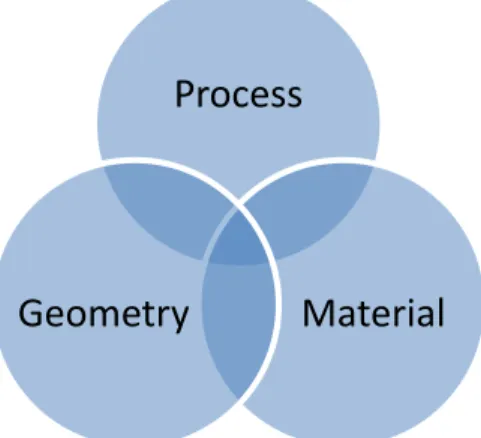
The industry and academy have for a long time been working with integrated product development. While this has been useful these new multi material solutions further emphasizes on the need to integrate product development and production development, in order to create solutions that are lighter, more environmentally friendly and less costly. For this to be successful, the authors have identified a number of areas where product development tools and methods need to be evaluated and possibly improved in order to identify possible manufacturing issues and solve them early in design phases. As visualized in figure 12; manufacturing process (including joining and painting), component geometry and material selection are interlinked and the optimum solution can be found where these three topics overlap each other.
Figure 12. The interlinked relationship between process, geometry and material
Future studies
Existing product development tools and methodologies need to be evaluated with regards to these new demands. Also, in future research, these new multi material approaches needs to be evaluated when looking at end of life disassembly and recycling, to ensure that the energy savings in the production and usage phase are not sacrificed in the end of life phase. There is a possibility that new end of life vehicle directives should be written with these new ways of designing vehicles in mind.
References
[1] L. W. Cheah, "Cars on a Diet: The Material and Energy Impacts of Passenger Vehicle Weight Reduction in the U.S.," Massachusetts Institure of Technology, Cambridge, 2010. [2] W.-H. Hucho, Aerodynamics of Road Vehicles - Fourth
Edition, USA: SAE, 1998.
[3] E. Tempelman, "Multi-Parametric study of the effect of materials substitution on life cycle energy use and waste generation of passenger car structures," Transportation Research Part D, pp. 479-485, 2011.
[4] S. D. Davis, S. W. Diegel and R. G. Boundy, Transportation Energy Data Book, edition 28, Oak Ridge: U.S. Department of Energy, 2009.
[5] S. C. Davis, S. W. Diegel and R. G. Boundy, Transportation Energy Data Book - Edition 31, Oak Ridge: U.S. Department of Energy, 2012.
[6] J. V. Busch and J. R. Dieffenbach, "Economic Criteria for Sensible Selection of Body Panel Materials," SAE Technical Paper Series, 1991.
[7] D. M. Baskin, S. Dinda and T. S. Moore, "A Simple Approach to Selecting Automotive Body-in-White Primary-Structural Materials," SAE Technical Paper Series, 2002.
[8] F. Henriksson and K. Johansen, "Towards Applying the Boothroyd, Dewhurst and Knight Methodology for Cost Estimation on Fibre Composite Manufacturing - A Theoretical Approach," in Swedish Production Symposium, Gothenburg, 2014.
[9] D. L. Thurston, "A Materials Selection Tool for Automotive Structural and Body Skin Systems," SAE Technical Paper Series, 1988.
[10] Granta Design, "Cambridge Engineering Selector EduPack 2015," Granta Design, Cambridge, UK, 2015.
[11] S. Das, "The Cost of Automotive Polymer Composites: A Review and Assessment of DOE's Lightweight Materials Composites Research," U.S. Department of Energy, Oak Ridge, Tennessee, USA, 2001.
[12] G. Peterson and A. Peterson, "Cost-Effectiveness of a Lightweight BIW Design for 2020-2025: An Asssessment of a Midsize Crossover Utility Vehicle Body Structure," SAE International, 2013.
[13] N. Lutsey, "Review of Technical Literature and Trends Related to Automobile Mass-Reduction Technology," University of California, Davis, Davis, 2010.
Process
Material
Geometry
Page 8 of 8
[14] Lotus Engineering Inc., "An Assessment of Mass Reduction Opportunities for a 2017-2020 Model Year Vehicle Program," The International Council on Clean Transportation, 2010. [15] C. Caffrey, K. Bolon, G. Kolwich, R. Johnston and T. Shaw,
"Cost-Effectiveness of a Lightweight Design for 2020-2025: An Assessment of a Light-Duty Pickup Truck," SAE International, 2015.
[16] T. W. Skszek, M. Zaluzec, J. Conklin and D. Wagner, "MMLV: Project Overview," SAE International, 2015.
[17] C.-H. Choi, S.-S. Park and T.-W. Hwang, "Development of Composite Body Panels for a Lightweight Vehicle," SAE Technical Paper Series, 2001.
[18] S. Logan, A. Kizyma, C. Patterson and S. Rama, "Lightweight Magnesium Intensive Body Structure," SAE Technical Paper Series, 2006.
[19] R. Tucker, "Trends in Automotive Lightweighting," Metal Finishing, March/April 2013.
[20] J. Lanfranchini, "The Role Of The Automobile In The Development Of The Plastics And Composite Materials Industry," SAE International, pp. 1.76-1.85, 1988. [21] M. Pfestorf and J. van Rensburg, "Improving the Functional
Properties of the Body-In-White with Lightweight Solutions Applying Multiphase Steel, Aluminium and Composites," SAE Technical Paper Series, 2006.
[22] BMW Sweden, "BMW 7 series Carbon Core," [Online]. Available:
http://www.bmw.se/_common/shared/newvehicles/7series/sed an/2015/showroom/highlights/carbonslider/img/7-series-sedan-carbon.jpg . [Accessed 13 08 2015].
[23] SAE, "Cadillac pursues aluminum/steel mix for new CT6 luxury sedan," 01 04 2015. [Online]. Available:
http://articles.sae.org/13986/ . [Accessed 13 08 2015]. [24] Volvo Cars, "Volvo XC90 Media," [Online]. Available:
https://www.media.volvocars.com/se/sv-se/models/all-new-xc90/2016/photos . [Accessed 11 08 2015].
[25] Automotive.com, "Techie: 2015 Mercedes Benz C-Class Reinvents, Redefines Itself Photo Gallery," [Online]. Available: http://www.automotive.com/news/techie-2015- mercedes-benz-c-class-reinvents-redefines-itself-153585/photo_01.html . [Accessed 16 10 2015]. [26] P. Mårtensson, D. Zenkert and M. Åkermo, "Integral or
Differential Design for a Cost Effective Composite Automotive Body Structure," in ECCM16 - 16th European Conference on Composite Materials, Seville, 2014.
[27] P. Mårtensson, "Cost and weight effective composite design of automotive body structures," KTH, Stockholm, 2014. [28] K. Martinsen, S. Hu and B. Carlson, "Joining of Dissimilar
Materials," CIRP Annuals - Manufacturing Technology, 2015. [29] H. Karlsson, "Mixade material för fordonsindustrin -
Litteraturstudie - "State-of-the-art" - Fogningsmetoder/limning för dagens fordonsindustri," IVF Industriforskning och utveckling, Mölndal, 2005.
[30] G. Meschut, M. Matzke, R. Hoerhold and T. Olfermann, "Hybrid technologies for joining ultra-high-strength boron steels with aluminum alloys for lightweight car body structures," Procedia CIRP, vol. 23, pp. 19-23, 2014. [31] S.-i. Takahashi, K. Toda, K. Ichihara and K. Uchiyama,
"Recent Approaches for Saving Energy in Automotive Painting," SAE Technical Paper Series, 1991.
[32] F. Ju, J. Li, G. Xiao and J. Arinez, "Quality flow model in automotive paint shops," International Journal of Production Research, pp. 6470-6483, 2013.
[33] G. Yu, "Simulation of Automotive Paint Curing Process in an Oven," Metal Finishing, March/April 2013.
[34] S. Emde, N. Boysen and A. Scholl, "Balancing mixed-model assembly lines: A computational evaluation of objectives to smoothen workload," International Journal of Production Research, pp. 3173-3191, 2010.
[35] L. Wenping and H. Yuming, "Car sequencing in mixed-model assembly lines from the perspective of logistic optimization," in IEEE Internation Conference on Automation and Logistics, Qingdao, 2008.
[36] C. Lee and G. Vairaktarakis, "Workforce planning in mixed model assembly systems," Operations Research, pp. 553-567, 1997.
Contact Information
Fredrik Henriksson: Fredrik.henriksson@liu.se and/or +46 (0)13-28 46 55
![Figure 1. Vehicle mass divided per subsystem (after [1])](https://thumb-eu.123doks.com/thumbv2/5dokorg/4982243.137029/2.918.54.437.80.625/figure-vehicle-mass-divided-subsystem.webp)
![Figure 2. Material distribution (in %) of an average American car by year (adapted from [4, 5])](https://thumb-eu.123doks.com/thumbv2/5dokorg/4982243.137029/3.918.53.454.52.540/figure-material-distribution-average-american-car-year-adapted.webp)
![Figure 5. BMW Carbon Core [22]](https://thumb-eu.123doks.com/thumbv2/5dokorg/4982243.137029/4.918.498.880.182.422/figure-bmw-carbon-core.webp)
![Figure 8. Mercedes C Class body showing significant aluminum integration into the Body-in-White [25]](https://thumb-eu.123doks.com/thumbv2/5dokorg/4982243.137029/5.918.91.456.60.270/figure-mercedes-class-showing-significant-aluminum-integration-white.webp)
![Figure 11. Graph showing maximum service temperature (X axis) and coefficient of thermal expansion (Y axis) of material families plausible for vehicle bodies [10]](https://thumb-eu.123doks.com/thumbv2/5dokorg/4982243.137029/6.918.63.455.97.310/figure-showing-temperature-coefficient-expansion-material-families-plausible.webp)