Civil and Architectural Engineering
Kungliga Tekniska Högskolan
BIM Software Capability and
Interoperability Analysis
An analytical approach toward structural
usage of BIM software (S-BIM)
Master thesis in Building Technology No. 442
Department of Civil and Architectural Engineering March 2016
Ali A. Taher Supervisors
Folke Björk, KTH Building Technology Kjartan Gudmundsson, KTH Building Technology
KTH Architecture and the Built Environment
PREFACE
In the name of Allah, the most gracious, the most merciful, are the best words ever which I start this thesis with. All praise and thanks belongs to Allah, the Lord of the worlds, and peace and blessings of Allah be upon the last Prophet “Mohammed” and upon his pure and generous family.
This research presented in this thesis was carried out at the department of civil and architectural engineering at the royal institute of technology (KTH) 2015.
I would also like to express my thanks and sincerest gratitude to my supervisors; Professor Folke Björk, with the inestimable advice and guidance of associate professor Kjartan Gudmundsson, to whom I want to thank for providing valuable reviewing, thoughtful feedback and comments the final report to present this master programme thesis.
I am particularly thankful to a number of people who do not work with me but have been friends for the last three years of my life in Sweden, for your support and for all those nice moments, we have spent together: Dr. Saif Wahid Jasim, Dr. Ahmed M.Qasim, Basil Jawad, Mohamed Ameen, Firas Jawad, Safa Alkhazraji & Khalid Agha. I apologize to those whose names I did not mention, but who should also be here.
Last but not least of course, I wish to express my deepest appreciation to my beloved mother, for her infinite love, devotion, encouragement and support that words cannot truly express, my kind brothers and sisters and their families, for their endless encouragement and support, and finally to my father, a great man whom we all missed.
Stockholm, March 2016
Ali Abdulhasan Taher
ABSTRACT
Over the past few decades, major advances have occurred in computer technology to optimize technical solutions. BIM is more than drawings it has played a major role in building design and modelling, construction and maintenance information. Thus, BIM established itself as an alternative to CAD technique, where BIM can be used for views, sections, elevations, and quantity takeoff. . Because of its advantages and the ease and simplicity of modelling process, the use of BIM is growing rapidly and becoming more popular than CAD. Nowadays BIM has no specific standard common platform and number of competitors, compatibility issues occur since every provider of BIM software such as Autodesk Revit, and Rhino BIM that have a common platform namely IFC, CIS/2 and ISM. This study focused on the structural analysis of BIM models. Different commercial software (Autodesk products and Rhinoceros) are presented through modelling and analysis of different structures with varying complexity, section properties, geometry, and material. Beside the commercial software, different architectural and different tools for structural analysis are evaluated (dynamo, grasshopper, add-on tool, direct link, indirect link via IFC).
Keywords: BIM, S-BIM, Autodesk Products, Revit, Robot Structural Analysis, Dynamo, STAAD pro, Rhinoceros, Grasshopper, Tekla, Karamba, IFC, ISM, CIS/2.
CONTENTS
PREFACE ... I ABSTRACT ... III LIST OF FIGURES ... V LIST OF TABLES ... NOTATION ... CHAPTER 1: INTRODUCTION ... 11.1 RESEARCH AIM AND OBJECTIVES ... 3
1.1.1 RESEARCH QUESTIONS ... 4
1.1.2 HYPOTHESES & EXPECTED CONTRIBUTION TO KNOWLEDGE ... 4
1.2 THESIS OUTLINE ... 5
1.3 LITERATURE REVIEW & STUDY BACKGROUND ... 6
1.3.1 THESIS BACKGROUND LITERATURE STUDY AT A GLANCE ... 7
1.4 RESEARCH METHODOLOGY ... 7
1.4.1 STRATEGY OF INQUIRY & STEP ANALYSIS ... 8
1.4.2 TOWARD A COMPARING PLATFORM OF ANALYSING ... 8
1.4.2.1 EXPERIMENTAL MAPPING & VISUALIZATION ... 9
1.5 RESEARCH SCOPE AND LIMITATIONS ... 9
CHAPTER 2: BIM SOFTWARE & DATA MODELS ... 11
2.1 BIM, ORIGINS & ELEMENTS ... 13
2.1.1 BIM SOFTWARE ... 15
2.1.1.1 REVIT BUILDING APPLICATION ... 15
2.1.1.2 RHINOCEROS & RHINOBIM ... 18
2.1.1.3 DYNAMO REVIT + GRASSHOPPER RHINO, NEW TECHNIQUES ... 19
2.1.2 STRUCTURAL BIM (S-BIM) TOOLS ... 21
2.2.1 THE INDUSTRY FOUNDATION CLASSES (IFC) ... 22
2.2.2 THE CIMSTEEL INTEGRATION STANDARDS (CIS/2) ... 24
2.2.3 INTEGRATED STRUCTURAL MODELING (ISM) ... 24
CHAPTER 3: ANALYSIS OF S-BIM FOR AUTODESK AND RHINOCERS PRODUCTS FOR SIMPLE 2D STRUCTURES ... 27
3.1 ANALYSIS METHODS ... 27
3.2 STRUCTURE-1 SIMPLY SUPPORTED STEEL COLUMN (LATERAL- TORSIONAL BUCKLING TEST) ... 31
3.2.1 RESULTS OF TEST (1) ... 33
3.2.3 EVALUATION OF TEST (1) ... 36
3.3 STRUCTURE-2 SIMPLY SUPPORTED TIMBER BEAM ... 38
3.3.1 RESULTS OF TEST (2) ... 41
3.3.3 EVALUATION OF TEST (2) ... 45
CHAPTER 4: ANALYSIS OF S-BIM TOOLS (IFC, CIS/2) FOR 3D STEEL STRUCTURE ... 47
4.1 INTRODUCTION ... 47
4.2 ANALYSIS METHODS ... 49
4.3 TESTS BASIS ... 51
4.4 DATA EXCHANGE FROM TEKLA STRUCTURES (BIM) TO REVIT ... 53
4.4.1 EXPORT TO REVIT VIA IFC ... 54
4.4.2 EXPORT TO REVIT VIA CIS/2 ... 55
4.4.3 EXPORT TO REVIT VIA DWG ... 56
4.5 BIM MODELLING AND ANALYSIS HANDLING ISSUES ... 57
4.5.1 EXPORT TO REVIT VIA CIS/2 ... 58
4.5.2 ADD-INS (INTEGRATION) LINK BETWEEN ROBOT AND REVIT ... 59
4.6 RESULTS OF TESTS ... 61
4.8 EVALUATION OF TEST (3) ... 65
CHAPTER 5: CONCLUSION AND FUTURE RESEARCH ... 67
APPLICABILLITY OF S-BIM TOOLS ... 70
NURBS GEOMETRY BIM SOFTWARE DIRECT LINK BETWEEN BIM SOFTWARE VIA S-BIM TOOL ... 71
DIRECT LINK BETWEEN BIM SOFTWARE VIA S-BIM TOOL ... 71
A- USING KARAMBA IN GRASSHOPPER AND STRUCTURAL ANALYSIS FOR DYNAMO IN DYNAMO ... 71
B- ADD-INS WIZARD (INTEGRATION-AUTODESK REVIT STRUCTURE) DIRECT LINK BETWEEN RVT AND RSA ... 72
INDIRECT LINK (IFC, CIS/2, ISM) ... 72
5.2 FUTURE RESEARCH ... 74
BIBLIOGRAPHY ... 77
APPENDIX A ... 83
APPENDIX B ... 95
LIST OF FIGURES
FIGURE 2.1: AN INFORMATION CYCLE IS FOLLOWABLE BY APPLYING THE BIM CONCEPT
DURING THE BUILDING LIFECYCLE ... 14
FIGURE 2.2: THE INTEGRATION OF A PHYSICAL MODEL WITH AN ANALYTICAL MODEL THAT CAN BE EDITED FOR STRUCTURAL ANALYSIS... 16
FIGURE 2.3: REVIT STRUCTURE OFFERS ALL THE TOOLS FOR STRUCTURAL DESIGN AS WALLS, COLUMNS, BEAMS, TRUSSES, CONCRETE, REBAR, STEEL CONNECTIONS, AND MORE ... 16
FIGURE 2.4: THE ANALYSIS PROCESS THROUGH REVIT BASED ON PROVIDED SPECIFIC ANALYSIS TOOLS. ... 17
FIGURE 2.5: THE REVIT EXTENSION CIS/2 WIZARD ADD ON S-BIM TOOL ... 17
FIGURE 2.6: RHINOCEROSBIM SOFTWARE MAIN INTERFACE ... 18
FIGURE 2.7: THE VISUAL SCRIPTING INTERFACE IN GRASSHOPPER ... 20
FIGURE 2.8: BUILDINGSMART.SE WEBSITE INTERNAL SERVER ERROR MESSAGE ... 23
FIGURE 2.9: ISM ENABLED PRODUCTS (REVIT, STAAD PRO, IFC…ETC.) ... 25
FIGURE 3.1: THE WORKFLOW INFORMATION FROM BIM PROCESS TO FEM RESULTS FOR STRUCTURE 1 ... 28
FIGURE 3.2: THE WORKFLOW INFORMATION FROM BIM PROCESS TO FEM RESULTS FOR STRUCTURE 2 ... 29
FIGURE 3.3: LEFT: SIMPLY SUPPORTED COLUMN. RIGHT: CROSS SECTION (HEB-PROFILE) ... 31
FIGURE 3.4: SCREEN DUMP OF STRUCTURE 1 REPRESENTATIONS IN DIFFERENT BIM SOFTWARE (A) DYNAMO (B) REVIT (C) ROBOT STRUCTURAL ANALYSIS (D) STAAD PRO ... 33
FIGURE 3.5: LEFT: SIMPLY SUPPORTED BEAM. RIGHT: CROSS SECTION ... 38
FIGURE 3.6: ALGORITHM MODELLING SHAPES USED THROUGH RHINOCEROS AND KARAMBA IN STRUCTURE 2 ... 40
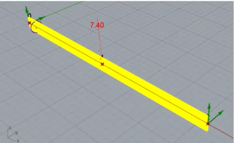
FIGURE 3.7: TIMBER BEAM MODEL WITH MID-SPAN LOAD IN RHINO (GH+K PLUG-INS) ... 41
FIGURE 3.8: TIMBER BEAM MODEL WITH MID-SPAN LOAD IN REVIT ... 41
FIGURE 3.9: TIMBER BEAM MODEL WITH MID-SPAN LOAD IN ROBOT STRUCTURAL ANALYSIS 42 FIGURE 3.10: TIMBER BEAM MODEL WITH MID-SPAN LOAD IN STAAD PRO ... 42
FIGURE 4.1: CROSS SECTION OF THE BUILDING ... 47
FIGURE 4.2: FLOOR PLAN OF THE BUILDING ... 48
FIGURE 4.3: THE WORKFLOW INFORMATION FROM BIM PROCESS TO FEM RESULTS FOR STRUCTURE 3 ... 49
FIGURE 4.4: 3D BUILDING BIM MODELLED IN TEKLA ... 52
FIGURE 4.5: THE 3D STEEL STRUCTURE AFTER EXPORT TO REVIT VIA IFC FORMAT ... 54
FIGURE 4.6: THE 3D STEEL STRUCTURE AFTER EXPORT TO REVIT VIA CIS/2 FORMAT. ... 55
FIGURE 4.7: THE 3D STEEL STRUCTURE AFTER EXPORT TO REVIT VIA DWG FORMAT ... 56
FIGURE 4.8: USING REVIT EXTENSIONS CIS/2 IN EXPORTING 3D BIM MODEL ... 58
FIGURE 4.9: USING AUTODESK ADD-INS TOOL IN EXPORTING 3D BIM MODEL TO REVIT ... 59
FIGURE 4.10: STRUCTURE PERSPECTIVE AFTER EXPORTING TO REVIT VIA CIS ... 60
FIGURE 4.11: STRUCTURE PERSPECTIVE AFTER EXPORTING TO REVIT VIA INTEGRATION ... 60
FIGURE 4.12: SELECTED STUDY BEAM IN 3D BUILDING BIM ... 61
FIGURE 4.13: SELECTED STUDY COLUMN IN 3D BUILDING BIM ... 62
FIGURE 4.14: SELECTED STUDY BEAM TO COLUMN CONNECTION IN 3D BUILDING BIM ... 63
LIST OF TABLES
TABLE 1.1: LIST OF COMMERCIAL SOFTWARE USED IN THE THESIS ... 5
TABLE 3.1: DESIGN CRITERION FOR ANALYSIS STRUCTURE 1 ... 32
TABLE 3.2: LATERAL BUCKLING TEST RESULTS FOR SIMPLY SUPPORTED STEEL COLUMN. ... 34
TABLE 3.3 DESIGN CRITERION FOR ANALYSIS STRUCTURE 2 ... 38
TABLE 3.4: MOMENT RESISTANCE TEST RESULTS FOR SIMPLY SUPPORTED TIMBER BEAM ... 43
TABLE 4.1: DESIGN CRITERION FOR ANALYSIS STRUCTURE 3 ... 51
TABLE 4.2: DESIGN CRITERION FOR ANALYSIS STRUCTURE 3 ... 51
TABLE 4.3: MOMENT RESISTANCE TEST RESULTS FOR 3D STEEL STRUCTURE ... 63
TABLE 5.1 : BIM AND FEA SOFTWARE INTEROPERABILITY WITH S-BIM TOOLS ... 68
LIST OF ACRONYMS
Item Description
2D Two dimensions, length and width
3D Three dimensions, includes depth
4D Three dimensions, includes depth + Cost
5D Three dimensions, includes depth + Cost + Time
BIM Building Information Modelling
S-BIM Structural Building Information Modelling
IFC Industry Foundation Classes
CIS/2 CIMSteel Integration Standards
ISM Integrated Structural Modeling
FEM Finite element method
FEA Finite element analysis
LIST OF COMMERCIAL SOFTWARE USED IN
THIS THESIS
Description
Acronyms Version Release
Date BIM – Commercial software
Autodesk AutoCAD 2016 ACAD M.49.0.0
Autodesk Revit 2015 RVT Build: 20140606_1530 2014
Autodesk Robot Structural Analysis 2015 RSA 28.0.0.5335 2014
Autodesk Dynamo DYN 0.8.2 2015
STAAD Pro V8i SPro 20.07.10.65 2014
Rhinoceros Rhino 5.0 SR11 10/2015
Tekla Structures 20 TEK 20.0 Service Release 1 3/2014
Structural BIM – (S-BIM Tools)
Structural Analysis for Dynamo - 0.2.1 7/2015
Revit Extensions for Autodesk Revit 2015 Extensions 3.0.8.0 2014
CIS/2 Import-Export 2015 for Revit CIS/2 9.0.0 5/2015
ISM Revit Link V8i (SELECTseries 7) ISM 8.11.12.3 8/2015
Grasshopper WIP GH 0.9.0076 8/2014
Karamba 3d K 1.1.0
CHAPTER 1
INTRODUCTION
The construction industry such as automotive and aeronautics is undergoing a revolution. In
recent years, Building Information Modeling1 (BIM) has had an impact on the traditional
construction process (Eastman, 2011; Granroth, 2008) and has played a major role in the transition to more industrial construction methods, which has reduced time and costs based on the digital modeling and management of information. Some countries such as Denmark, Singapore and the United Kingdom have decided and mandate this integrated approach toward the Building Information Modeling and European Parliament has already released a call for proposal with the main objective of the development of “a common European strategy for the introduction and specification of Building Information Modelling (BIM) in Europe’s
public works”2. Member States have until April 2016 to reflect the new rules of the guidelines
related to public procurement (EUPPD3, 2014) into national law. The European Parliament
recommends the use of digital processes such as BIM in public contracts to improve efficiency and quality of the interchanges in the phases of bidding and competitions for public projects.
The use of BIM or information management model for the design and construction of a building is already widely applied in Sweden (mostly in the architectural design process) including the academic support toward providing a platform for the Building Lifecycle
Management (BLM)4. BIM can be described as a process to generate and manage information
on buildings throughout their lifecycle and enables the integration of dynamic information of the building [an integrated approach toward different branches of information such as architectural and structural information in the design phases of a building]. The software
1 (2014). What Is BIM | Building Information Modeling | Autodesk. Retrieved August 14, 2015, from
http://www.autodesk.com/solutions/building-information-modeling/overview.
2 (2015). Support of a common European network aiming at aligning ... Retrieved August 14, 2015,
from
http://ec.europa.eu/DocsRoom/documents/10423/attachments/1/translations/en/renditions/native.
3 (2014). BIM And The New EU Public Procurement Directives: An ... Retrieved August 17, 2015, from
http://www.mondaq.com/x/315484/Building+Construction/BIM+And+The+New+EU+Public+Procu rement+Directives+An+Update.
4 (2010). AIA Guide to Building Life Cycle Assessment in Practice. Retrieved August 14, 2015, from
CHAPTER 1. INTRODUCTION
system is based on a digital 3D presentation of the building (Azhar, 2011). However, it is not necessary that all users apply the 3D digital model and the level of information and detail of the model depends on the projects and context. The implementation of information exchange in construction is not only a technical decision but also a business decision in order to achieve better communication and an improved decision process as well as reduced construction time
and costs (Smith & Tardif, 2012). BIM5 is a new concept in the construction industry and is
defined as a collection of programs with different tools used in the design, production and finally in the management of buildings; it contains the object-oriented models that contain information about the building during the construction process (Shamloo & Mobaraki, 2011). Effective strategy for implementing BIM software must not only be based on adapting the construction design process to the corresponding technology, but also through an extensive technical understanding of the capability of different related software and applications.
The use of BIM in structural design involves the choice of appropriate platform. Beside the BIM softwares’ internal capabilities characteristics, the interoperability, data standards and communication between softwares must also be taken into consideration (Pazlar & Turks,
2008; Grilo & Jardim-Goncalves, 2010). For instance, the IFC6 format (Industry Foundation
Classes) is a data model/standard that describes objects, their characteristics and their relationships. The IFC is a part of the international standard STEP (Pratt, 2001) or "Standard for Exchange of product data" (ISO 10303). Since March 2013, the IFC are certified ISO 16739 (Liebich, 2012). IFC aim to ensure the interoperability of BIM software. As we intend to show in this thesis, the import and export capability of IFC from one application to another is not completely satisfactory.
5 (2009). Building information modeling – BIM software and ... Retrieved August 14, 2015, from
http://www.bim.construction.com/.
6 (2012). Industry Foundation Classes Whitepaper - Bentley. Retrieved August 15, 2015, from
CHAPTER 1.1 RESEARCH AIM AND OBJECTIVES
1.1 RESEARCH AIM AND OBJECTIVES
The aim of this thesis is to illustrate how BIM can be used in structural design and calculations. The objective is particularly to compare some of the available tools for structural analysis and design. This comparison has been done by first establishing a platform of reference cases that could then be used to compare the results as well as the capabilities and interoperability of the software and the different data formats.
According to the literature review, there is not any specific integrated differentiating analytical platform to compare different components in BIM software and the related data standards.
In accordance to the main objective, several structures (2D and 3D) with various serviceability in different software and data standards were used. Ultimately, the results could be used for making a "BIM execution plan" in structural analysis and design.
1.1.1 RESEARCH QUESTIONS
The aim is to describe various aspects of BIM and S-BIM to compare them in a manner that may help improve the structural design process and to describe their strengths and weaknesses. This involves:
The analysis of different structural capabilities of the common BIM software and compare them.
The examination of different data models and standards in accordance with the interoperability.
CHAPTER 1.1.2 HYPOTHESES & EXPECTED CONTRIBUTION TO KNOWLEDGE
1.1.2 HYPOTHESES & EXPECTED
CONTRIBUTION TO KNOWLEDGE
There is a traceable trend of standardization in the international construction industry in both the determination of BIM models and the interoperability of different BIM applications.
We believe that there is a lack of proper communication between different BIM software and the open source file format of IFC containing some practical deficiencies capability. In order to examine this hypothesis, this study compares a selection of current BIM applications through the modeling both simple and more advanced structures. The BIM applications have also been tested with common FEA structural software and their structural add-Ins (plug-ins) tools in both normal BIM (Revit) and algorithm way (Dynamo and Rhino Grasshopper).
Finally, this study attempts to describe the reliability of different BIM software and data standards including the S-BIM, BIM and related data models.
CHAPTER 1.2 THESIS OUTLINE
1.2 THESIS OUTLINE
The first chapter is a general introduction to the study followed by a second chapter that provides a comprehensive literature review on the specifications of different software and data standards, such as IFC, CIS/2, ISM and Revit, STAAD Pro (BIM SOFTWARE & DATA MODELS). Chapters 3 and 4 include the comparative case study of BIM, S-BIM and the related add-ins and data standards with simple and more advanced models. The third chapter describes the applicability of structural BIM for simple 2D structures with different section properties and different materials; various properties and different materials have been investigated in the applicability of the structural BIM and with different materials (steel and timber), geometries (column and beam) and different physical section properties (rectangle and I section). In the fourth chapter the applicability of S-BIM tools are tested with the three dimensional steel structure from.
Dynamo and Rhino Grasshopper software beside the current BIM application such as Revit during these two chapters have also been used to differentiate the subjects and evaluate them. S-BIM (Carrasco & Navarro, 2013) is a new concept of in sense of structural integrity of BIM; for S-BIM the Autodesk RSA (Robot structural Analysis) has been tested to assess the links and capability of RSA in various structural design analysis. Furthermore this study includes the application of a well-known reliable structural design software, STAAD Pro, and compared the results with RSA. The efficiency of data models standards such as IFC, CIS/2 and ISM have also been examined during the third and fourth chapters.
1.3 LITERATURE REVIEW
The term BIM has a contextual meaning the interpretation of which depends on disciplines (Granroth, 2008). According to the literature study of the author, no comparative studies have been done on the reliability of structural BIM and structural add-ins for BIM. The focus of this literature study is on the literature on the specifications of different software and data standards (for example IFC, CIS/2, ISM and Revit, STAAD Pro). The literature used may be categorized according to the following topics:
BIM origins and elements. BIM data standards and models.
CHAPTER 1.3.1 THESIS BACKGROUND LITERATURE STUDY AT A GLANCE
1.3.1 THESIS BACKGROUND LITERATURE
STUDY AT A GLANCE
In general, the theoretical framework of BIM (Lu & Li, 2011), there seems to be a lack of research on the effective integration of sense of technical requirements to facilitate the technology and its application (Singh et al., 2011).
In most of the published studies, BIM models are associated with un-unified data7. BIM and
CAD models were developed in parallel where a productivity improvement of 57% was demonstrated with BIM software (Sacks et al., 2010) concerning the design of a building
facade. However, problems of the study of this thesis emerged in the IFC exchange data
model was incomplete that technically confirmed the need for the data standard improvement. There are also interdisciplinary studies (Aram et al., 2013) to flow the information with BIM.
1.4 RESEARCH METHODOLOGY
The core methodology of the study of this thesis is based on an analytical approach [software capability comparing] by analyzing the key factors of software performance differentiation; the final evaluation relies heavily on the comparison criteria of the performances. All these comparisons would advocate our conclusion about the subjects (software or data model) performances and the results would emphasis the significance of developing such an “analysis platform”.
This research is focused on the comparison on the software and software standards of BIM and structural design and the formalization of the associated results based on the experimental approach to evaluate different common BIM software and interoperability data models mostly by analyzing different criteria and investigate the capabilities of the cases. This research focused on the comparison on the software standards of BIM and structural design, based on the experimental approach to evaluate different common BIM software and interoperability
data models through the modeling simple and more advanced structures. An overview of the
BIM software and structural BIM tools is shown in table 1.1. This study includes:
7 (2014). Re-use of structural elements | S-BIM & Sustainability for ... Retrieved August 20, 2015, from
CHAPTER 1.4 RESEARCH METHODOLOGY
Using indirect link Structural Analysis for Dynamo between DYN and RSA. Using indirect link (CIS/2 Import and Export 2015) from Revit to RSA via CIS/2. Using indirect link (ISM Revit plug-in) from Revit to SPro via ISM.
Using indirect link Karamba between DYN and RSA.
Using Autodesk direct link (Robot Structural Analysis link) from Revit to RSA. Using indirect link (ISM Revit plug-in) from Revit to SPro via ISM.
Table 1.1: List of commercial software used in the thesis.
Description Acronyms Version Release
Date BIM – Commercial software
Autodesk AutoCAD 2016 ACAD M.49.0.0
Autodesk Revit 2015 RVT Build: 20140606_1530 2014
Autodesk Robot Structural Analysis 2015 RSA 28.0.0.5335 2014
Autodesk Dynamo DYN 0.8.2 2015
STAAD Pro V8i SPro 20.07.10.65 2014
Rhinoceros Rhino 5.0 SR11 10/2015
Tekla Structures 20 TEK 20.0 Service Release 1 3/2014
Structural BIM – (S-BIM Tools)
Structural Analysis for Dynamo - 0.2.1 7/2015
Revit Extensions for Autodesk Revit 2015 Extensions 3.0.8.0 2014
CIS/2 Import-Export 2015 for Revit CIS/2 9.0.0 5/2015
ISM Revit Link V8i (SELECTseries 7) ISM 8.11.12.3 8/2015
Grasshopper WIP GH 0.9.0076 8/2014
CHAPTER 1.4.1 STRATEGY OF INQUIRY & STEP ANALYSIS
1.4.1 STRATEGY OF INQUIRY & STEP
ANALYSIS
In general, the main methodic approach is similar to the Grounded Theory (Dick, 2002) except that our categorization does not become a basis of any new theory. Furthermore, this study aims to explain different aspects of BIM and S-BIM with IFC, ISM and CIS/2 with a data gathering strategy in order to develop the needed platform for the hypothesis examination. Since our “substantive area” has been identified (Douglas, 2003), we have collected the needed data through the practical tests (chapters 3 & 4), to eventually link and visualize them and through the final chapter our “theoretical sampling” (Eisenhardt & Graebner, 2007) shapes the structure of a prospect software adaptation policy and an enhancement proposition.
1.4.2 TOWARD A COMPARING PLATFORM OF
ANALYSING
An experimental context based on the comparing processes of different components in BIM software and the related data standards (chapters 3 & 4) is the basis of the assessment of the performance evaluation based on our developed criteria in order to facilitate the structural design agents in the transitional phase to develop a deliverable structural phase design. The lack of interoperability between different software would be recognizable regarding the associated data elements models. This interoperability is necessary for the collaboration of agents working on the same model.
CHAPTER 1.4.2.1 EXPERIMENTAL MAPPING & VISUALIZATION
1.4.2.1 EXPERIMENTAL MAPPING &
VISUALIZATION
The possibility of developing algorithms of BIM structure modelling through Dynamo and Rhino Grasshopper software can bring about a new possibility for visualization and mapping and is discussed in chapters three and four.
1.5 RESEARCH SCOPE AND LIMITATIONS
The BIM software has been becoming more sophisticated by progressively integrating a growing number of features and there are still progresses to be made. A very important part of this progress is related to the software interoperability and data standards and communication between software. As we mentioned in the hypothesis, the import and export in the BIM application need to be more developed in order to make the operations automatic. This study is related to a practical assessment of the common BIM software and their compatibility to data standards for structural design. This thesis is also an attempt to develop a platform for comparison of structural BIM software.
CHAPTER 2
BIM SOFTWARE & DATA MODELS
“CAD helps people to draw. BIM helps people to construct.” - Richard Saxon
Previous studies show that the cooperation between professionals during the process contains the average of seven times re-entering the information (Grosrey, 2013) because the non-unified approaches of different members of a design team; the lack of coherence, effectiveness and interoperability cause waste of time and money. The solution that has been
ordinated since about twenty years ago is the use of BIM1. The construction industry has
shown an increased willingness to apply BIM to reach significant potential gains in projects. As mentioned in the first chapter of this thesis, the European Union has recently applied new
guidelines and “Procurement Directive”2 to encourage member states according to the usage
of digital tools. The definition of BIM varies and often has been explained depending on the activity that uses it (Jongeling, 2008). The “US National Building Information Model
Standard Project Committee”3 has defined BIM as:
“Building Information Modeling (BIM) is a digital representation of physical and functional characteristics of a facility. A BIM is a shared knowledge resource for information about a facility forming a reliable basis for decisions during its life-cycle; defined as existing from earliest conception to demolition.”
BIM improves the processes of design and construction and stage-based operational approach regarding the information exchange; eventually, it is an introduction to the age of information and communications technology in the building sector (Fountain, 2004) at the heart of the
1 (2011). NBS National BIM Library - free-to-use BIM objects. Retrieved August 27, 2015, from
http://www.nationalbimlibrary.com/.
“The National BIM Standard-United States® (NBIMS-US™) provides consensus based standards through referencing existing standards, documenting information exchanges and delivering best business practices for the entire built environment. With open BIM standards we can build detailed models then deliver accurate products that can be used during commissioning and operation to ensure facility functionality throughout the life of the facility and to deliver high performance, carbon neutral, and net zero energy based facilities.”
2 (2014). European Directive Officially Opens Public Procurement to ... Retrieved August 27, 2015,
from http://www.bimtaskgroup.org/european-directive-officially-opens-public-procurement-to-use-bim/.
3 (2015). National Building Information Modeling Standard Version 1 ... Retrieved August 27, 2015,
CHAPTER 2. BIM SOFTWARE & DATA MODELS
technological and economic control revolution (Beniger, 2009) integrating digital tools to the process of construction design and life-cycle and facilitating the market development. However, the effective application of BIM contains the implicit interoperability between the related software and data format standards. In other words, BIM is a working method or a
process4 mostly based on the collaboration around a digital information model (Hading &
McCool, 2015) in which each contributor uses the model, deriving and feeding an updating the information toward a final virtual object. BIM is a collective concept of how to formulate, implement, and store the information in a systematic and quality assured manner (Jongeling, 2008).
There is controversy regarding the influences of BIM as a powerful tool providing a real leap
in terms of quality and productivity in the construction sector5 reducing time, decreasing cost
and contributing to the sustainability values6. As Pontus Bengtson, BIM expert at WSP
(Winroth, 2012), emphasizes, BIM is primarily not about new technology, but about an attitude. The information-based approach would eventually reduce the level of risk (Jannadi & Almishari, 2003) and increase the quality of design and implementation. Moreover, the digital model would have a better economic performance with optimized management costs (Bryde et al., 2013). The mentioned Information-based approach requires the standardization of data formats and interoperability.
In a broader view, BIM is valuable in terms of the generation of reliable and quality
information that preserve the investments in sense of asset management7.
4 (2011). Building Information Modeling (BIM) - InfoComm. Retrieved August 28, 2015, from
http://www.infocomm.org/cps/rde/xbcr/infocomm/Brochure_BIM.pdf.
5 (2013). improving efficiency and productivity in the construction ... Retrieved August 28, 2015, from
http://www.cefrio.qc.ca/media/uploader/Improving_efficiency_and_productivity_in_the_constructi on_sector_final.pdf.
6 (2014). Integration of BIM and Business Strategy - The Whole ... Retrieved August 28, 2015, from
https://www.wbdg.org/pdfs/integratebim_harris.pdf.
7 (2015). Leveraging the Relationship between BIM and Asset ... Retrieved August 31, 2015, from
https://www.ice.org.uk/getattachment/disciplines-and-resources/best-practice/relationship- between-bim-and-asset-management/BIM_Modelling-and-Asset-Management_Position-Paper.pdf.aspx.
“Asset management is defined by ISO 55000 as the ‘coordinated activity of an organisation to realise value from assets’. Asset management translates business objectives into asset-related decisions, plans and actions within a strategic framework using a set of processes, techniques and tools. It seeks to optimise the cost, risk and performance of assets over their life cycle at an individual asset, asset system and asset portfolio level.”
CHAPTER 2.1 BIM, ORIGINS & ELEMENTS
2.1 BIM, ORIGINS & ELEMENTS
“BIM is not CAD. BIM was never meant to be CAD. CAD is a replacement for pen and paper, a documentation tool. By comparison, BIM programs are design applications in which the documentation flows from and is a derivative of the process, from schematic design to construction to facility management.” - Pete Zyskowski, Cadalyst8
The industry demand of an efficient design process and sustainability is favored by new working methods and tools that enable all stakeholders to integrate the knowledge and objectives (Rezgui et al., 2010). The main purpose of Building Information Modeling (BIM) is the development of such a context offering the capacity to manage the corresponding information. As mentioned before, BIM is mainly a methodology based on the use of computable information (Arayici & Aouad, 2010) about the physical and functional characteristics of a building or infrastructure to facilitate interoperability and collaboration between different actors involved in the construction process, providing reliable support and shared decision-making platform (Rezgui et al., 2011). There is currently a high demand for professionals capable of organizing workflows platform (Clevenger et al., 2010) in the sector with a broad view of all the processes that occur in the life cycle of construction.
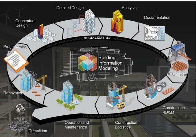
In recent years, the BIM trend has been changing the industry methodical traditions and developing the communicational attitude between the various project-based contributors and stakeholders although there are currently no documental regulative approach in Sweden (Juntikka, 2015). Beside the BIM three dimensional representation models, by definition, it contains 4D and 5D models (Jongeling, 2008) in integration with the so-called 3D model in order to provide the project with the traceable production planning and time and cost visualization (Figure. 2.1).
From architects to developers, actually all the stakeholders, enjoy the benefits of the collaborative method of BIM which uses starts from 3D models and matures into interactive deployment through databases in a dynamic modeling sense and far further than intelligent 3D digital models which integrate all types of construction-related data. Nowadays, “BIM
8 (2009). The World According to BIM, Part 1 | Cadalyst. Retrieved September 7, 2015, from
CHAPTER 2.1 BIM, ORIGINS & ELEMENTS
manager”9 has been started to be defined as a new interdisciplinary branch as a person in
charge of the implementation and coordination of BIM Plan10. BIM could also be considered
as a communication tool (Cerovesk, 2011) in the form of visualization in simulated construction processes (Kamat & Martinez, 2005).
Figure 2.1: An information cycle11 is followable by applying the BIM concept during the building lifecycle.
The following chapters give a review of a comparative matrix12 that has been developed in
order to analyze the flow of associated information for the exchanges between different BIM software focused on the construction design process.
9 (2010). 10 Things Every BIM Manager Should Know - Vico Software. Retrieved September 4, 2015,
from http://www.vicosoftware.com/vico-blogs/guest-blogger/tabid/88454/bid/22833/10-Things-Every-BIM-Manager-Should-Know.aspx.
10 (2012). Facilities BIM Execution Plan - MIT. Retrieved September 4, 2015, from
http://web.mit.edu/facilities/maps/MIT_BIM_execution_plan.pdf.
11 (2013). Why Project Managers are perfect for the role of Information ... Retrieved September 1, 2015,
from http://evolution5.co.uk/bim-why-project-managers-are-perfect-for-the-role-of-information-manager/.
12 (2012). BIM Tools Matrix - BIMForum. Retrieved September 5, 2015, from
CHAPTER 2.1.1 BIM SOFTWARE
2.1.1 BIM SOFTWARE
Currently, the set of tools, techniques and concepts that allow realizing the BIM approach toward general construction design is known internationally as BIM software (Guan-pei, 2010).
2.1.1.1 REVIT BUILDING APPLICATION
Revit13 (Revise Instantly) as an eighteen year old software and more than thirteen releases (2
to 3 releases per year) is mainly developed as an architectural tool by PTC14 (Parametric
Technology Corporation and Charles River Software, patented by Leonid Raiz and Irwin
Jungreis) and since then has become the only15 “completely parametric Building Information
Modeling tool available”. In 2002, Autodesk16 purchased a Revit and developed a family of
tools and applications based on the main concept.
Autodesk Revit17 is capable of 4D level (building's lifecycle traceability) which means that it
is completely suitable for structural design (the thesis scope) in 3D and interoperability using “building model's database”. Autodesk Revit® Structure software integrates a physical model consisting of multiple materials with an independent analytical model that can be edited and used for efficient structural analysis, design and construction description (Figure 2.2). As the design changes made during the analysis automatically update the physical model and the construction documents automatically which is a direct presentation of information from the same underlying database. This key feature of Revit Structure is the reason why it is so easy and flexible to use, while virtually eliminating coordination errors and improve overall quality of descriptions and documentation.
13 (2012). Revit Structure and BIM - i-Theses. Retrieved August 30, 2015, from
https://i-theses.com/nl/images/stories/pdf/revit_structure_bim_mar07.pdf.
14 PTC: Technology Solutions for Ongoing Product & Service ... Retrieved September 5, 2015, from
http://www.ptc.com/.
15 (2014). Building Design Software | Revit Family | Autodesk. Retrieved September 5, 2015, from
http://www.autodesk.com/products/revit-family/overview.
16 (2008). Autodesk to Acquire Revit Technology Corporation. Retrieved September 5, 2015, from
http://investors.autodesk.com/phoenix.zhtml?c=117861&p=irol-newsArticle&ID=261618.
17 (2015). Building Design & Construction | Revit Family | Autodesk. Retrieved September 5, 2015,
CHAPTER 2.1.1.1 REVIT BUILDING APPLICATION
Figure 2.2: The integration of a physical model with an analytical model that can be edited for structural analysis.
Figure 2.3: Revit Structure offers all the tools for structural design as walls, columns, beams, trusses, concrete, rebar, steel connections, and more.
CHAPTER 2.1.1.1 REVIT BUILDING APPLICATION
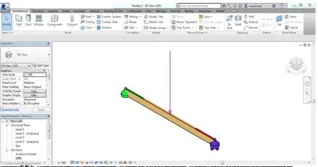
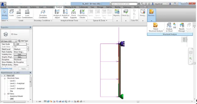
Figure 2.4: The analysis process through Revit based on provided specific analysis tools.
CHAPTER 2.1.1.1 2.1.1.2 RHINOCEROS & RHINOBIM
2.1.1.2 RHINOCEROS & RHINOBIM
The Rhino Software (Rhinoceros18) is a 3D surface modeler with an engine of NURBS
(Non-Uniform Rational Basis Splines19) as a curve generator (Farin, 1999) by defined control points
on a coordinated basis which are compatible with the majority of visual projections. Rhino opens with four windows XY, XZ (front view), YZ (to the right) and prospective and can enlarge one of its windows by clicking the left button of the window in a single large window and reduce by the same method; there is a simultaneous visualization of the movement of the pointer in the 4 windows in (Figure 2.6).
Figure 2.6: RhinocerosBIM software main interface.
18 (2013). Rhinoceros. Retrieved September 9, 2015, from https://www.rhino3d.com/.
CHAPTER 2.1.1.3 DYNAMO REVIT + GRASSHOPPER RHINO, NEW TECHNIQUES
As an additional expansion of Rhino, RhinoBIM is developed by “Virtual Build
Technologies20” and “Robert McNeel & Associates21” to adapt Rhino more to the concept of
BIM. As it has been mentioned in the developer’s website RhinoBIM22 is a “plug-ins that
enhances Rhino”; the “first module” includes: Structural Design & Editor.
Clash & Clear Analysis.
Quantity take offs in BIM Reporter. IFC & CIS2 Translators.
User Definable database.
2.1.1.3 DYNAMO REVIT + GRASSHOPPER
RHINO, NEW TECHNIQUES
Dynamo23 is an open-source plugin for Revit (and now Robot Structural Analysis24),
described as visual programming to which adds an icon to the “complements” as "Dynamo 0.X". Dynamo, the visual integration of data modification, is mostly helpful in
Complex and Parametric Modelling, Additional features to the software, Automating tedious tasks,
Exporting data and results to Excel.
In this thesis, the main purpose of application is “transforming computational design in
functional structures in Revit”25. Dynamo is also considered as the Grasshopper for Revit.
20 (2010). Virtual Build Technologies. Retrieved September 12, 2015, from http://www.vbtllc.com/.
21 Robert McNeel & Associates - North America. Retrieved September 12, 2015, from http://www.mcneel.com/.
22 (2015). RhinoBIM - Tools for Design through Construction. Retrieved September 12, 2015, from
http://rhinobim.com/page/download-3.
23 (2014). Learn | Dynamo BIM. Retrieved September 17, 2015, from http://dynamobim.com/learn/. 24 (2014). Structural Software | Robot Structural Analysis | Autodesk. Retrieved September 17, 2015,
from http://www.autodesk.com/products/robot-structural-analysis/features/all/list-view.
25 (2013). Transforming computational design in functional structures ... Retrieved September 17,
CHAPTER 2.1.1.3 DYNAMO REVIT + GRASSHOPPER RHINO, NEW TECHNIQUES
The Grasshopper26 plugin for Rhino is also working with a possibility of “visual scripting
interface”27 (Fig. 2.6) although there are some operational differences.
If we consider the Rhino's ability in developing “complex geometries” and consistently the Grasshopper becomes a form-generating plugin which could not be considered as the Dynamo’s main concern as Revit is not mainly developed as a “freeform geometry” software.
Eventually in accordance with the basic concept of BIM of “the management of building information”, the Dynamo and Revit are more fitted to the procedure.
Figure 2.7: The visual scripting interface in Grasshopper.
26 (2010). Geometry Gym BIM - Grasshopper. Retrieved September 17, 2015, from
http://www.grasshopper3d.com/group/geometrygym.
27 (2015). Dynamo: More Than Grasshopper Lite | CASE. Retrieved September 17, 2015, from
CHAPTER 2.1.2 STRUCTURAL BIM (S-BIM) TOOLS
2.1.2 STRUCTURAL BIM (S-BIM) TOOLS
As mentioned before, BIM could be considered as a design methodology for the information of a building through its lifecycle. Structural BIM (S-BIM) literally collects the information
of the structural28 part of the design based on the concept of collaborative approach and
develops the related digital representation. Consequently, S-BIM (Carrasco & Navarro, 2013) increases the efficiency and the overall quality of the building and the corresponding software.
Basically, the referred information includes all the structural29 elements and the related
analysis and detailing. The workflow effectiveness in BIM is based on the information sharing and exchange, which efficiently influence the collaboration and, by applying the S-BIM technology (Zhang & Hu, 2011), it would even be possible to analyze the structural behavior during construction and safety during the construction process through simulation.
2.2 BIM & DATA EXCHANGE STANDARDS &
MODELS
“Drawing is Dead – Long Live Modelling” - CPIC30 There is no doubt that the contemporary construction industry is the result of a complex process involving multiple actors; the collaborative value is difficult to achieve since the coordination of the produced information must be unified and integrated with a sense of control of the processes that generate the deliverables enabling the design development and contributing to the procedure as a whole (Grilo & Jardim-Goncalves, 2010).
Basically, BIM is a digital file format (not only a virtual one) which integrates all of the technical information of a building. This file contains every building component object and its characteristics and the relationships between objects that mostly are described as the junctions; the provided information is far beyond the simple geometric shapes.
28 (2012). BIM Integrity in Structural Engineering - i-Theses. Retrieved August 30, 2015, from
https://i-theses.com/nl/images/stories/pdf/bim_integrity_in_structural_engineering_feb07%5B1%5D.pdf.
29 (2013). The Power of BIM for Structural Engineering. Retrieved August 30, 2015, from
http://www.cadac.com/nl/brochures/Documents/autodesk-revit-2013-structural-engineering-brochure-en.pdf.
30 (2013). CPIC » Drawing Is Dead – Long Live Modelling. Retrieved September 7, 2015, from
CHAPTER 2.1.2 STRUCTURAL BIM (S-BIM) TOOLS
The construction digital information must be enhanced in accordance with the collaboration among stakeholders through the design process and lifecycle; it must be shared, reliable and durable. On the traditional process of design beside the issue of information documentation, the similar data has been being applied for several time using non-compatible agents which the BIM and unified data models would completely avoid these kind of problems; the new approach toward databases such as “cloud” (Jiao, et. al, 2013) would facilitate the process even more.
BIM is not a file format or a data pattern31; the standards listed here, such as IFC and CIS/2
standard, are mechanisms to transfer data from one software application to another, but are
not themselves BIM project models32.
2.2.1 THE INDUSTRY FOUNDATION CLASSES
(IFC)
The Industry Foundation Classes (IFC) format is the data model (Isikdag et al., 2007)
developed by the buildingSMART33 and is a part of the international standard STEP (Standard
for Exchange of Product data, ISO 1030334) (Pratt, 2001). Since 2013, IFC is certified as ISO
1673935 in accordance with the interoperability of BIM software data exchange. Most software has adopted this standard to some extent but the inter-software data exchange is not
yet flawless. The importance of sharing information36 in BIM context emphasizes the
significance of IFC standards (or the other models) facilitating the procedure of interoperability and enabling project members to participate, regardless of the software they use.
31 (2011). Data Exchange Standards in the AEC Industry - Autodesk. Retrieved September 14, 2015,
from
http://images.autodesk.com/adsk/files/data_exchange_standards_in_the_aec_industry_final.pdf.
32 (2014). AEC (UK) BIM Protocol. Retrieved September 14, 2015, from
https://aecuk.files.wordpress.com/2012/09/aecukbimprotocol-v2-0.pdf.
33 (2005). Home | buildingSMART | buildingSMART |. Retrieved August 26, 2015, from
http://www.buildingsmart.org/.
34 (2002). ISO 10303 STEP Standards - STEP Tools, Inc. Retrieved August 26, 2015, from
http://www.steptools.com/library/standard/.
35 (2011). ISO 16739:2013 - Industry Foundation Classes (IFC) for ... Retrieved August 26, 2015, from
http://www.iso.org/iso/catalogue_detail.htm?csnumber=51622.
36 (2014). Solibri | About BIM and IFC. Retrieved August 26, 2015, from
CHAPTER 2.2.1 THE INDUSTRY FOUNDATION CLASSES (IFC)
The IFC is the information that describes the designed objects throughout its lifecycle37
(design, construction, and operation) and from different points of view (architecture, structure, thermal, Management, etc.) providing the form, characteristics, relationships with other
objects regardless the software based file format38. The international standard STEP (ISO
10303-2139) does guarantee the stability, universality, and independence of the IFC data
model format. Eventually, the IFC standard would prepare the needed communication and operation platform for all BIM applications based on a unified database.
The IFC could be considered as a standard, neutral, and independent language which has been being developed under the vision of “the development and adoption of interoperable standards
for openBIM” by buildingSMART40 with the main goal to evolve the IFC standard and
promote the concept of BIM in the construction sector. Within BuildingSMART, each country contributes as volunteers to advance the concept and the results have been reflected in
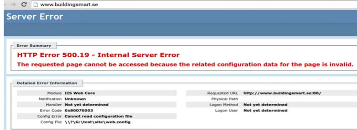
the “Standards Library, Tools and Services”41. It is interesting that the Swedish division of
buildingSMART has not been activated.
Figure 2.8: buildingSMART.se website internal server error message.
37 (2014). Exporting to Industry Foundation Classes (IFC) | Revit ... Retrieved August 26, 2015, from
http://knowledge.autodesk.com/support/revit-products/learn- explore/caas/CloudHelp/cloudhelp/2015/ENU/Revit-DocumentPresent/files/GUID-6EB68CEC-6C17-4B16-A509-30537F666C1F-htm.html.
38 (2012). Industry Foundation Classes Whitepaper - Bentley. Retrieved August 26, 2015, from
http://ftp2.bentley.com/dist/collateral/docs/bentley_institute/White_paper_IFC.pdf.
39 (2010). Reading and Writing STEP Data Sets - STEP Tools, Inc. Retrieved August 26, 2015, from
http://www.steptools.com/support/stdev_docs/roselib/read_write.html.
40 (2005). Home | buildingSMART | buildingSMART |. Retrieved August 30, 2015, from
http://www.buildingsmart.org/.
41 (2005). Home | buildingSMART | buildingSMART |. Retrieved August 30, 2015, from
CHAPTER 2.2.2 THE CIMSTEEL INTEGRATION STANDARDS (CIS/2)
2.2.2 THE CIMSTEEL INTEGRATION
STANDARDS (CIS/2)
The plug-in of CIS/2 (CIMsteel Integration Standards version 242), available for Autodesk®
Revit® Structure, is a good example of the promotion of standard formats by Autodesk. CIS/2 is an open standard for the exchange of engineering data structure (Crowley & Watson, 2000), dedicated to steel structures (Lipman, 2006). The management of import and export operations in Autodesk Revit Structure in CIS/2 format is provided by the related extension in Revit® and offered to customers who bought Revit Structure. As Reed (2003) emphasizes:
“Successful integration of an automated process into a project delivery system depends on the ability to describe the desired result of the process in a manner understandable to its automation technology. Similarly, it depends on the ability of the automation technology to describe the actual result of the process in a manner understandable to subsequent processes.”
2.2.3 INTEGRATED STRUCTURAL MODELING
(ISM)
Some cooperation between different software solution developers and data standard companies have an ongoing cooperation in order to enhance the interoperability. As an
example Bentley Systems43, Autodesk Company, and Tekla Corporation44, the digital
information model provider has developed a “collaboration to advance the interoperability of
software within Building Information Modeling”45. The Bentley's workflows Integrated
Structural Modeling (ISM)46 provides the “structural practitioner” with the following:
42 (2003). CIS/2 -- CIMsteel Integration Standard - STEP Tools, Inc. Retrieved September 14, 2015,
from http://www.steptools.com/support/stdev_docs/express/cis/.
43 Bentley: Architecture, Engineering, Construction Design ... Retrieved September 15, 2015, from
http://www.bentley.com/.
44 (2008). Tekla | Model-based software for construction, infrastructure ... Retrieved September 15,
2015, from http://www.tekla.com/us.
45 (2012). Bentley Systems and Tekla Advance Interoperability of ... Retrieved September 15, 2015,
from
http://www.bentley.com/en-US/Corporate/News/News+Archive/2011/Quarter+2/tekla+advance+ilnteroperability.htm.
46 (2010). Integrated Structural Modeling - Bentley. Retrieved September 15, 2015, from
CHAPTER 2.2.3 INTEGRATED STRUCTURAL MODELING (ISM)
Interoperability among all ISM-compatible software; Common structural data model;
Trackable and comparable results;
Visually and textuality during the changes of the model; Publishing collaborative features;
Extra integrative visualization tools, facilities, and open source capability.
Figure 2.9: ISM enabled products (Revit, STAAD Pro, IFC…etc.) 47
CHAPTER 3
ANALYSIS OF S-BIM FOR AUTODESK AND
RHINOCERS PRODUCTS FOR SIMPLE 2D
STRUCTURES
In this chapter, several BIM commercial software and their structural BIM tools have been studied through the modeling of two simple structures in steel and timber materials as well as beam and column physical structures.
3.1 ANALYSIS METHODS
In this thesis, the applicability of structural BIM is investigated by testing it on two, relatively simple, 2D structures. Firstly, a simply supported steel column that is a widely used element of building construction is investigated. Secondly, a simply supported timber is of interest in order to clarify whether S-BIM tools would be enabled to handle an anisotropic timber construction material as simple supported.
Furthermore, the capabilities of transferring the analytical model from and to S-BIM and commercial BIM software have been studied. The implemented workflow used in the tests has been illustrated in Figure 3.1-3.2 respectively.
In the first case, different software applications for Revit and Dynamo have been applied:
Using indirect link Structural Analysis for Dynamo between DYN and RSA.
Using indirect link (CIS/2 Import/Export 2015) from Revit to RSA via CIS/2.CHAPTER 3.1 ANALYSIS METHODS
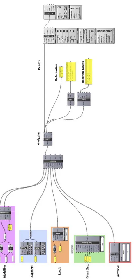
The second structure is also modelled by Revit and Rhinoceros BIM commercial software. The new S-BIM (Karamba) is used as FEM software beside SPro and RSA for analysis processes, which applied via S-BIM tools:
Using indirect link Karamba between DYN and RSA.
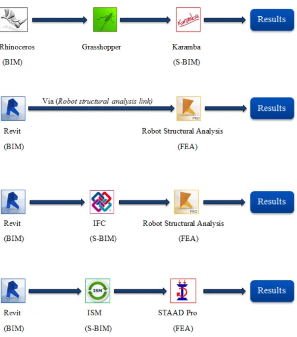
Using Autodesk direct link (Robot Structural Analysis link) from Revit to RSA.Figure 3.1: The workflow information from BIM process to FEM results for Structure 1 Figure 3.1: The workflow information from BIM process to FEM results for Structure 1 Figure 3.1: The workflow information from BIM process to FEM results for Structure 1
CHAPTER 3.1 ANALYSIS METHODS
Using indirect link (ISM Revit plug-in) from Revit to SPro via ISM.CHAPTER 3.2 STRUCTURE-1 SIMPLY SUPPORTED STEEL COLUMN (LATERAL TORSIONAL BUCKLING TEST)
In order to analyze different structures modelled with BIM software, S-BIM tools should be able to handle a number of specific parameters.
The input parameters in order of workflow are as follows:
1. Section properties (dimensions, area, moment of inertia, etc.). 2. Geometry (length, and effective length).
3. Material properties (yield stress, elasticity, density, and shear modulus). 4. Loads (load magnitude, and load position).
5. Boundary conditions (fixed, pinned, and roller).
6. Design data (moment capacity, shear capacity, design factor, etc.).
7. Results (deflections, section forces, and Euro code check by employing FEM).
The final results from FEM software are compared with correct hand calculations which performed according to Eurocode.
CHAPTER 3.2 STRUCTURE-1 SIMPLY SUPPORTED STEEL COLUMN (LATERAL TORSIONAL BUCKLING TEST)
3.2 STRUCTURE-1 SIMPLY SUPPORTED STEEL
COLUMN (LATERAL TORSIONAL
BUCKLING TEST)
The first structure in this chapter is extracted from course handouts from the course AF2213, Steel and Timber Structures given at KTH 2015. A pure flexural column buckling test is performed, is 2.85 m simply supported steel column (pinned – roller ends). The structure is free to deflect in the stiff direction and the column is subjected to an axial load PEd = 371 kN
in combination with transverse uniformly distributed load WEd = 3.32 kN/m. The column is
made a H-section, HEB100 of steel type S235. The static system of the steel beam and the cross section are shown in figure 3.3.
b tw h tf r y WEd L PEd z x HEB 100 Z
Figure 3.3: Left: Simply supported column. Right: Cross section (HEB-profile)
Both applied loads (arbitrary load and distributed uniformly load) and the chosen HEB100 cross section provide sufficient bending and shear strength but insufficient lateral column buckling resistance. This model is used in order to ensure that the structural BIM software and its tools meet the design requirements [not according Eurocode 3 through different software environment]. Relevant design criteria for Eurocode (EC3) of the steel column are found by:
CHAPTER 3.2 STRUCTURE-1 SIMPLY SUPPORTED STEEL COLUMN (LATERAL TORSIONAL BUCKLING TEST)
Table 3.1: Design criterion for analysis Structure 1
All the parameters that need to be evaluated and the lateral column buckling design criteria are presented in Appendix A.
Design Criteria Hand calculations Robot Structural
Analysis STAAD Pro
Bending moment EC3: 6.2.5 EN 1993-1-1:2003 EN 1993-1:2005/AC:2009 EN-1-1:2005
Shear resistance EC3: 6.2.6 EN 1993-1-1:2003 EN 1993-1:2005/AC:2009 EN-1-1:2005
CHAPTER 3.2.1 RESULTS OF TEST (1)
3.2.1 RESULTS OF TEST (1)
The applicability of modelling and structural BIM (S-BIM) tools are tested by applying simply supported steel column through different BIM software based on design criteria and the design parameters in Appendix A and the results are shown in Table 3.2. The calculation procedures are shown in Appendix A (A.2 Procedures of Test 1). The procedures demand different choices according to the modelling and analyzing process.
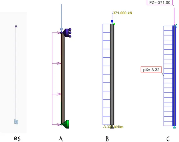
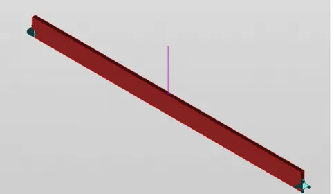
(A) (B) (C) (D)
Figure 3.4: Screen dump of Structure 1 representations in different BIM software (A) Dynamo (B) Revit (C) Robot structural analysis (D) STAAD Pro
CHAPTER 3.2.1 RESULTS OF TEST (1)
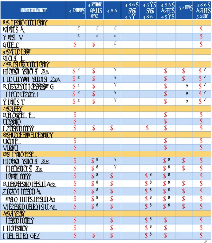
Table 3.2: Lateral buckling test results for simply supported steel column.
refers to no problem or error occurs while refers to feature does not work or parameter is not available
Description Dyn (Plug-Dyn
In) RVT RVT ↓ RSA RSA ↓ RVT RVT ↓ / RSA SPro RVT ↓ SPro 1. Section properties Class classification (1,2,3,4)
2
2
Height (h)
1
3
Width (b)
1
3
Web thickness (tw)
1
3
Flange thickness (tf)
1
3
Radius (r)
1
3
Area (A)
3
Shear area (Ay, Az)
2
Moment of inertia (Iy, Iz)
Elastic section modulus (Wel,y)
2
Plastic section modulus (Wpl,y)
2
Radius of gyration (i)
2
2. Geometry
Length (L)
Effective length (Leff)
2
2
3. Material properties
Yield stress (fy)
Modulus of elasticity (E)
Shear modulus (G)
Weight (W)
4. Loads Magnitude (P, q)
Position
5. Boundary conditions Pinned
Roller
5
6. Design dataCritical bending moment (Mcr)
2
2
Resistance moment (Mb.Rd)
2
2
Slenderness parameter (λLT)
2
4
2
Imperfection parameter (αLT)
2
4
2
Reduction factor (χLT)
2
4
2
7. Results Deflection
2
2
Section forces
2
2
CHAPTER 3.2.2 TEST (1) NOTES
Notes for table 3.2:
1) Sections properties standards in Dynamo are not available for any type of material; however, the user can create any cross section dimensions and extrude the length (L) in depth.
2) This parameter is not available in Revit.
3) Revit does not provide European steel sections as its defaults. The user must either (a) add a UK library to Revit Library Content, where UK library has European steel sections such as IPE, HEA, HEB, etc.; or (b) install Revit Extensions database tool to Revit for more standard sections.
4) Slenderness parameter (λLT) in Robot is 0.65, but it is 0.73 from the hand calculations.
Thus, the imperfection parameter (αLT) and reduction factor (χLT) and thereby the final
member stability check (0.76) is deferent with no influence with compared to hand calculations (0.97).
5) Dynamo package Structural Analysis for Dynamo contains limited supports function, only fixed, pinned, free options are given. Roller and other supports types are not available.
Notes for figure 3.4:
1) The coordinate system differs for different software.
2) In Revit, the analytical line is in placed in the top surface of the column, but the analytical representation of the column is convergent to the centerline of the section, i.e. there is no influence to the final performed results for test steel column simply supported. However, the coordinate system should be taking into considerations with complex structures especially where connections located.
3) Coordinate system in both Revit and Robot is different compared to STAAD Pro, thus,
it should take into consideration variation degree of freedom (DOF) xxxfff 1 i.e. Revit
coordinates DOF is defined as fxxfff corresponding to xxffff in STAAD Pro.
1) (x) refers to a fixed degree of freedom while ( f ) refers to free degree of freedom. First
three marks are related to translations in (X, Y, Z) and rest are related to rotations around (X, Y, Z).
CHAPTER 3.2.3 EVALUATION OF TEST (1)
3.2.3 EVALUATION OF TEST (1)
The first evaluation of simply supported steel column performed tests with BIM model is given depending on Table 3.11 tests results:
Dynamo Result 1/5
In the first test, the Dynamo obtains one credit (1/5 rating) because many parameters are missing, since sections properties standards in Dynamo are not available for any type of material, however the user can create any cross section dimensions and extrude the length (L)
in depth. Analytical performed properties area (A), section moment (Wel,y, Wpl,y) and moment
of inertia (Iy, Ix) can only be performed by adding operation functions individually to calculate the specific parameter. No section forces and deflections can be obtained through Dynamo, consequently neither design parameters nor design calculations can be determined.
Dynamo Plug-In (structural analysis for dynamo) Result 3/5
Dynamo plug-ins tool structural analysis for dynamo drives Dynamo through Robot directly, thus it allows using any common sections i.e. material properties are given, nodes may be support, section forces can be evaluated and deflections can be calculated. On other hand, there is no availability to assess the design criteria, where no design parameters could be found, and it is not possible to evaluate cross section resistance according to Eurocode.
RVT Result 2.5/5
In Revit the cross section dimensions, specifications, boundary conditions and load can be defined, while the structural stability cannot be analyzed.