Use of a rock ramp for grade control - Dueñas Bridge case
10
0
0
Full text
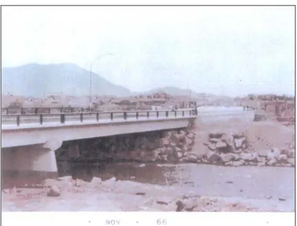
(2) Kuroiwa et al.. Figure 1. View of the Dueñas Bridge in 1966. This photograph was taken from the left bank. Notice that river flows underneath the two openings of the bridge.. 2.. Background Information The Dueñas Bridge is a two-span crossing structure supported by abutments in the right and left banks and a central pier. At first, the river flowed underneath the two openings of the bridge as seen in Figure 1. Since its construction, finished in 1966, the river morphology has undergone major changes due to the construction of other bridges, accumulation of sediment of foreign origin (mainly garbage) and the construction of remedial works. The so called remedial works not only did not solve the problem at hand, but accelerated the rate of incision of the river.. Figure 2. View showing the bed level in 2001. Notice that the river flows underneath one opening. Also notice scour in the right bank (left) and leftovers of a remedial work.. The El Ejercito Bridge is located 2.1 km (1.3 miles) upstream of the Dueñas Bridge. The bed has lowered by 18.5 m (60.70 feet) at that location. 134.
(3) Use Of A Rock Ramp For Grade Control – Dueñas Bridge Case. At the Dueñas Bridge the river level had descended 8 m (26.7 feet) approximately. At the time the Dueñas Bridge had been designed, the designers considered that the width of the river was 60 m (196.9 feet), but the occupants of both banks have been pouring garbage and waste to narrow the stream and add land to their properties. The narrowing of the stream has caused deepening of the river. Officers of the Ministry of Transportation and Communication (MTC) were hired by INVERMET to rebuild the foundation and reinforce the river bed in 1978. The original right abutment of the bridge is not compromised because due to the incision of the left opening of the bridge it does not flow water underneath the right opening. Even a two-lane road has been built underneath the right opening. Scour of the river bed has continued even after the remedial works where conducted. The foundation has been undermined below the bottom of the reconstructed foundation. Because safety of the bridge users was endangered motorized traffic was interrupted in October 2001, increasing the traffic load in the other bridges. The collapse of the bridge would have catastrophic consequences because the bridge deck could dam the Rimac River. The pressure might eventually destroy the deck, producing a dam break phenomenon that could rapidly erode both banks, leading to the destruction of houses located near the cliffs formed by the incision of the river. Several bridges located downstream, such as Faucett Bridge or Emisor Bridge could also collapse, when shear stresses induce the removal of their foundation materials. This document presents the temporary solution that allowed scour mitigation at the Dueñas Bridge during the 2001 – 2002, 2002 – 2003 and the current wet seasons. Although this erosion control work was considered as an emergency measure, it is still in service. 3.. Evolution of the Rímac River morphology The Rimac River has undergone a process of incision caused by the construction of civil works and human activity that have induced the narrowing of the stream. The existing morphology indicates that Peru Avenue, located 200 m from the river axis, might have been the right floodplain of the river in prehistoric times, and the Morales Duarez Avenue had been built on the ancient left floodplain. In addition, conglomerates formed by alluvial deposits left by the paleo Rimac River mainly compose most of Lima´s soil. Any inspection hole or trench shows that a deep conglomerate exists underneath the surface. This conglomerate is mainly composed by round pebbles, cobbles, boulders, and fine material. According to personal communications, old aerial photographs show that in reach of interest, the Rimac used to be a braided river. The Dueñas Bridge, built in 1966 is 70 m (229.7 ft) long and 20.60 m (67.5 ft) wide. 135.
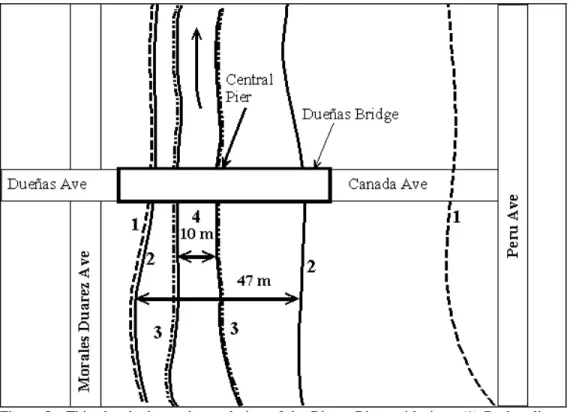
(4) Kuroiwa et al.. Riprap protection had been built to train the river upstream of the bridge. At the time of the construction of the bridge, the stream was 50 m (164 ft) wide. Narrowing of the stream, together with the training of the river and the construction of civil works has caused significant changes in the stream morphology. The incision of the stream was more pronounced in the left opening of the river, exposing the foundation of the central pier and left abutment, so that additional footing was placed underneath the existing foundations of the central pier and the left abutment. A grade control structure was built in 1977. It consisted mainly of a concrete drop with a stone embedded in concrete apron built downstream of the drop for scour protection. This structure merely protected the bed upstream of the bed temporarily, but regressive erosion occurred downstream of the apron, leading to cracking of the structure because no major reinforcement was included.. Figure 3. This sketch shows the evolution of the Rimac River with time. (1) Broken lines show the limits of the Paleo Rimac River. (2) Limits of the river in 1966. (3) River bottom when remedial works had been built. (4) Width of the river in 2001.. 4.. Design Considerations The grade control structure was designed as a temporary measure against erosion. Therefore, a low return period was used. The 2-year return period and 5-year return period discharges were used. This structure has not yet been replaced.. 136.
(5) Use Of A Rock Ramp For Grade Control – Dueñas Bridge Case. The closest gauging station is R-2, located in Chosica, 40 km (25 miles) from the bridge. Although such station is far from the point of interest, its information is useful, because most of the basin is arid below 1000 meters above sea level (3280 ft) and when rainfall occurs in the lower reaches, it does not necessarily coincides with rain in the upper reaches. In addition, the Rio Blanco basin, a large sub-basin within the Rimac river basin, has been regulated by the Yuracmayo Reservoir. The two-year return period discharge is 129 m3/s (4555.6 ft3s-1) and the five-year return period discharge is 198 m3/s (6992 ft3s-1). As a reference, during the occurrence of the last ENSO (El Niño Southern Oscillation), the maximum discharge in the Rimac river was 200 m3s-1 (7062.9 ft3s-1 ). A large intake structure also exists upstream of the Dueñas bridge. It is owned by SEDAPAL, Lima´s municipal water company, and usually takes between 13 and 21 m3s-1 (459.1 – 741.6 ft3s-1). The river bed is mainly composed by cobbles and boulders so that infiltration is high in this reach. The river bed, as well as the banks needed to be protected against scour. Because the river bed cannot be lowered to place the erosion protection layers, the final rock level of the ramp will be accommodated approximately following the leveled ground (see figure at the end of the paper). A gradual change in slope is allowed from approximately 50 m (164 ft) upstream so that the critical cross section is covered with a layer 1.5 – 2 the calculated typical rock size. To compensate this change in level, the second portion of the ramp is made steeper. Two methods were used to calculate the typical rock size for protecting the river bed: the moment stability method proposed by Stevens and Simons (1971), which was developed using a theoretical framework, and Abt and Johnson (1991) developed experimentally at Colorado State University (CSU). The method by Stevens and Simons is thoroughly described in Richardson et al (1990). The expression developed by Abt and Johnson follows:. D50 = 5.23S 0.43 q d0.56 In the previous equation D50 is the equivalent rock size in inches; S is the slope of the bed to protect, and qd is the unit discharge in ft2 s-1. The unit discharge has been corrected to avoid failure of the rock elements by multiplying the unit discharge by 1.35. An additional correction factor is included due to the flow concentration that occurs in a riprap layer. In experiments conducted at CSU, it was noticed that flow had a tendency to form “rills” in which flow concentrated and the unit discharge could vary between 1 and three times the nominal unit discharge. This is due to the nature of riprap, which is composed by loose particles of variable size. When water flows through the interstices, smaller particles tend to be eroded away and rills are formed. The rock layer thickness is twice the calculated rock size (2 D50). The river width is approximately 9.5 m ( 31.2 ft) and the 137.
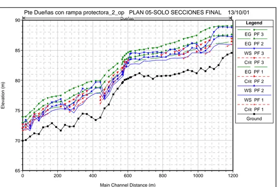
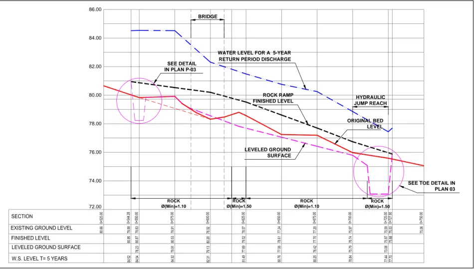
(6) Kuroiwa et al.. approximate slope is 0.023 or 2.3 %. The next tables summarize the calculations and results for designing the rock layer that will protect the bed. With the data gathered at the site, a first simulation was conducted to estimate the water levels for the 2-year and 5-year return period discharges. A second simulation, in which the rock ramp was included, was carried out as well. The rock ramp covers a reach starting 60 m upstream of the bridge axis to 115 m downstream of the axis. At the downstream end a deep toe has been considered to prevent removal of the particles. At the downstream end a hydraulic jump is expected The rock ramp is divided in two reaches. From section 0 + 550 to 0 + 620 it has a 1.33 % slope. From the latter section to 0 + 725 it has a 3.65 % slope until it intercepts the natural terrain. (See Figure 6 at the end of paper). The profiles of the backwater curves corresponding to the two-year flow discharge (129 m3s-1) and five-year flow discharge (198 m3s-1) are shown in Figure 4. This output was obtained using USACOE´s HEC-RAS 2.2b. The hydraulic simulations showed that the shear stress distribution was very uneven. Just downstream of the slope change the maximum shear stresses are produced. A summary of the results is presented below in Table 1. Table 1. Maximum shear stress and calculated rock size using stability of moments method.. Cross section. T Maximum shear Rock (years) stress (N/m2) diameter (m) 620 5 716.88 1.50 620 5 596.37 1.10 The rest 5 450 1.10. Safety factor. 1.51 1.34 1.75. In general, the safety factor is 1.5. Therefore, 1.10 m rock have been used, except in critical cross section were 1.5 m rocks were used. The critical reaches are located between sections 615 and 625 and 715 and 725 (until the downstream end of the toe). In this zone, a hydraulic jump is expected, so that large energy dissipation is expected. Partial calculations are included in Table 3 using the Abt and Johnson methodology. Rock size mainly depended upon unit discharge and bed slope. Downstream of the bridge, rocks were accommodated using a 2H: 1 V slope where possible (z= 2). Upstream of the bridge, rocks were following the contours of the terrain. A filter was not used in the placement of rock because the bed is mainly composed by cobbles and boulders. 5. Behavior of the Rock Ramp during the 2001 – 2002 and 2002 – 2003 wet season. The grade control structure was built by ICCGSA, a local contractor, in 2001. The construction was finished just before the beginning of the wet season. During the 2001 – 2002 wet season (December to April) the peak 138.
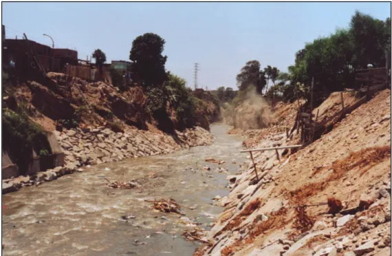
(7) Use Of A Rock Ramp For Grade Control – Dueñas Bridge Case Table 2. Rock size calulated using Abt and Johnson´s method.. Return Period 2 años 5 años. Discharge (m3/s) 129 198 Q (m3/s) b (m) q (m2/s) Failure factor Concentration factor qf (m2/s) qf (cfs/ft) S D50 (pulg) D50 (m). Nominal Diameter (m) 1.03 1.31. 197.55 9.50 20.80 1.35 2.50 70.18 755.45 0.0365 51.53 1.31. Pte Dueñas con rampa protectora_2_op PLAN 05-SOLO SECCIONES FINAL. 13/10/01. Dueñas. 90. Legend EG PF 3 EG PF 2. 85. WS PF 3 Crit PF 3. Elevation (m). EG PF 1 80. Crit PF 2 WS PF 2 WS PF 1 Crit PF 1. 75. Ground. 70. 65 0. 200. 400. 600. 800. 1000. 1200. Main Channel Distance (m). Figure 4. Graphical output of the hydraulic simulation using USACOE´s HEC-RAS 2.2b.. discharge was 94 m3s-1 (3319.6 cfs) at station R2 and during the 2002 – 2003 the peak discharge was 124 m3s-1 (4379 cfs). The behavior of the rock ramp was videotaped and it will be presented at the session. Upstream of the structure the flow is mild, but at the slope break the flow becomes very turbulent. Water impacts the rocks, angular in nature, and energy tends to dissipate. Figure 5 shows the Rimac River downstream of the Dueñas Bridge in January 2001. The authors have visited the area several times and no movement of rocks has been detected. The rock ramp is still in service and has not been replaced so far. 139.
(8) Kuroiwa et al.. Figure 5. This photograph shows the rock ramp downstream of the Dueñas bridge. This picture was taken from the right bank of the river.. 6. Conclusions and Recommendations a) The rock ramp has effectively protected the river bed against scour for almost two years. The river bed is stable and no major changes have occurred. b) The protective elements, measuring 1.1 m in most of the structure, and 1.5 m (5 ft) in the critical areas have remained in place. They could withstand unit discharges c) Although the design discharges have not been attained, it is expected that the structure will effectively protect the stream in the short term. Because a major sub basin has been regulated, lower peaks are expected at the site. d) The calculation methods for rock sizing presented in this paper produce similar results. e) The temporary works have become permanent. The city government has no intention of replacing the structure, because its behavior is satisfactory, although the measure was supposed to be temporary. f) It is advisable to analyze energy dissipation and aeration of rock. This structure may help aerate water allowing the release of dissolved gases. g) This work could have been an integral project, which included treatment of the surroundings. It is the authors´ opinion that the city missed an opportunity to produce a comprehensive treatment of the area. Acknowledgements The author acknowledges the support of the School of Civil Engineering of the National University of Engineering who made possible this presentation at Hydrology Days. The approval of the Dean of the 140.
(9) Use Of A Rock Ramp For Grade Control – Dueñas Bridge Case. School, Francisco Coronado, C.E, and the Board of Trustees of the School is gratefully acknowledged. The engineering study was funded by INVERMET. The authors wish to thank this agency for trusting them in the study of the remedial works presented in this paper. References Abt, S.R. y Johnson, T.L. (1991). Riprap Design for Overtopping Flow. Journal of Hydraulic Engineering. 117 (8). American Society of Civil Engineers. E.E.U.U. Julien, P.Y.(1995) Erosion and Sedimentation. Cambridge University Press. Cambridge, MA. E.E.U.U. Richardson, E; Simons, D.B.; Julien, P.Y. (1990) Highways in the River Environment. Federal Highway Administration. E.E.U.U. Rodríguez, E; Mansen, A; Kuroiwa, J; Abanto, G. (2001) Labores de Emergencia para la Mitigación de Socavación del Puente Dueñas. Para INVERMET.. 141.
(10) Kuroiwa et al.. 86.00 BRIDGE. 84.00. SEE DETAIL IN PLAN P-03. 82.00. WATER LEVEL FOR A 5-YEAR RETURN PERIOD DISCHARGE. 80.00. ROCK RAMP FINISHED LEVEL. HYDRAULIC JUMP REACH. ORIGINAL BED LEVEL. 78.00. LEVELED GROUND SURFACE. 76.00. 74.00. 72.00. SEE TOE DETAIL IN PLAN 03 ROCK Ø(Mín)=1.10. ROCK Ø(Mín)=1.50. Figure 6. Profile of the rock ramp at the Dueñas Bridge.. 142. ROCK Ø(Mín)=1.10. ROCK Ø(Mín)=1.50.
(11)
Figure
+2
Related documents
Furthermore The Rock and the River is written in the target language and is not adapted to a classroom for second language learners; one can therefore say that the book is
46 Konkreta exempel skulle kunna vara främjandeinsatser för affärsänglar/affärsängelnätverk, skapa arenor där aktörer från utbuds- och efterfrågesidan kan mötas eller
Both Brazil and Sweden have made bilateral cooperation in areas of technology and innovation a top priority. It has been formalized in a series of agreements and made explicit
The increasing availability of data and attention to services has increased the understanding of the contribution of services to innovation and productivity in
Av tabellen framgår att det behövs utförlig information om de projekt som genomförs vid instituten. Då Tillväxtanalys ska föreslå en metod som kan visa hur institutens verksamhet
Generella styrmedel kan ha varit mindre verksamma än man har trott De generella styrmedlen, till skillnad från de specifika styrmedlen, har kommit att användas i större
Re-examination of the actual 2 ♀♀ (ZML) revealed that they are Andrena labialis (det.. Andrena jacobi Perkins: Paxton & al. -Species synonymy- Schwarz & al. scotica while
Place Lalla Yeddouna / Liisa Gunnarsson Introduction / Exterior View From The Square Tutour: M.Aerni / Spring 2011.. 789
