Automated Computer Systems for
Manufacturability Analyses and
Tooling Design
Applied to the Rotary Draw Bending Process
JOEL JOHANSSON
Department of Product and Production Development
CHALMERS UNIVERSITY OF TECHNOLOGY
Göteborg, Sweden 2011
Automated Computer Systems for
Manufacturability Analyses and
Tooling Design
Applied to the Rotary Draw Bending Process
JOEL JOHANSSON
Department of Mechanical Engineering SCHOOL OF ENGINEERING
JÖNKÖPING UNIVERSITY Jönköping, Sweden
Department of Product and Production Development CHALMERS UNIVERSITY OF TECHNOLOGY
Automated Computer Systems for Manufacturability Analyses and Tooling Design Applied to the Rotary Draw Bending Process
Joel Johansson
ISBN 978-91-7385-510-5
© Joel Johansson, 2011
Doktorsavhandlingar vid Chalmers tekniska högskola Ny serie Nr 3191
ISSN 0346-718X
Department of Product and Production Development Chalmers University of Technology
SE-412 96 Gothenburg Sweden
Telephone + 46 (0)31-772 1000 Chalmers Reproservice
ABSTRACT
Intensive competition on the global market puts great pressure on manufacturing companies to develop and produce products that meet requirements from customers and investors. One key factor in meeting these requirements is the efficiency of the product development and the production preparation processes. Design automation is a powerful tool to increase efficiency in these two processes.
The benefits of automating the manufacturability analysis process, a part of the production preparation process, are shortened led-time, improved product perfor-mance, quality assurance, and, ultimately, decreased costs. Further, automation is beneficial as it increases the ability to adapt products to new product specifications with production preparations done in a few or in a single step. During the automation process, knowledge about the manufacturability analysis process is collected and stored in central systems, thus allowing full control over the design of production equipments.
Topics addressed in this thesis include the flexibility of design automation systems, knowledge-bases containing alternative design rules, the automation of the finite element analysis process, manufacturability analysis over several productions steps, and the determination of production limits by looping the automated manufacturabili-ty analysis process. These topics are discussed in connection with the rotary draw bending of aluminum profiles.
It is concluded that the concept of design automation can be applied to the manufactu-rability analysis process at different levels of automation depending on the characte-ristics of the implemented knowledge. The concept of object orientation should be adapted when implementing a knowledge-base and when developing the geometrical representations of the products. This makes a design automation system flexible enough to edit underlying knowledge and to extend the targeted design space. It is possible to automate the process of setting up, running, and interpreting finite element analyses to a great extent, enabling the design automation system to evaluate its own design proposals. It is also possible to enable such systems to consider sequences of manufacturing steps and loop them to develop decision support guiding engineers early in the design process, saving time and money while still assuring high product quality.
Keywords: Design For Manufacturability, Design Automation, Rotary Draw
AUTOMATED COMPUTER SYSTEMS FOR
MANUFACTURABILITY ANALYSES AND TOOLING DESIGN
ACKNOWLEDGEMENTS
The research presented through this thesis has been conducted in a cooperative study between Jönköping University, Sapa Group, Faurecia, and Ekenäs Mekaniska Verkstad. I am very grateful for the funding by Sapa Group and the Knowledge Foundation (in Swedish, KK-stiftelsen). It has allowed me to concentrate on this specific research area that is close to my passion for mechanical engineering and computer programming. I also express my gratitude to Chalmers University of Tech-nology, Department of Product and Production Development and Professor Rikard Söderberg, for kindly accepting me as a PhD student, making this work possible. I also express my gratitude to my supervisor, Professor Staffan Sunnersjö, for his enthusiasm and belief in my ideas and guidance in my research efforts. I also thank Mikael Cederfeldt, Fredrik Elgh, Dag Raudberget, and Roland Stolt for support and interesting discussions on the subject of design automation and research in general. Finally, I thank my family, especially my beloved wife, Synnöve Johansson, and my friends who have always stood by me, giving me their support and comfort.
Jönköping, 2011-02-07
_________________________________ Joel Johansson
AUTOMATED COMPUTER SYSTEMS FOR
MANUFACTURABILITY ANALYSES AND TOOLING DESIGN
PUBLISHED PAPERS
This thesis is based on the following published and appended papers:
Paper A – J. Johansson and S. Sunnersjö (2006). Automated Design of Rotary
Draw Bending Tools – An Approach Based on Generic CAD-Models Driven by Heuristic and Algorithmic Knowledge. EDMMP 2006, Wroclaw, Poland.
Paper B – J. Johansson (2007). A Flexible Design Automation System for Toolsets
for the Rotary Draw Bending of Aluminium Tubes. IDETC 2007, Neva-da, USA.
Paper C – J. Johansson (2008). Manufacturability Analysis Using Integrated KBE,
CAD and FEM. IDETC 2008, New York, USA.
Paper D – J. Johansson (2009). Automatic Producibility Analysis of the Draw
Bending of Aluminium Tubes with Several Bends. NAFEMS World Congress 2009, Hersonissos, Greece.
Paper E – J. Johansson (2009). Automated Manufacturability Analysis of the Draw
Bending of Complex Aluminum Profiles. IDETC 2009, San Diego, USA.
Paper F – J. Johansson (2011). Determining of the Manufacturing Limits for the
Draw Bending of Aluminum Profiles by Automated FEM-simulations. Submitted to the special issue of Journal of Manufacturing Science and Engineering: Advances in Plastic Forming of Metals.
AUTOMATED COMPUTER SYSTEMS FOR
MANUFACTURABILITY ANALYSES AND TOOLING DESIGN
TABLE OF CONTENTS
Chapter 1 Introduction ... 1
1.1 The importance of design automation for manufacturability analyses ... 1
1.2 Realization of design automation ... 1
1.3 Research objective and case of application ... 2
1.4 Research questions ... 4
1.5 Thesis outline ... 5
Chapter 2 Research Method ... 7
2.1 Applying the research method ... 8
Chapter 3 Frame of Reference ... 11
3.1 Design automation ... 11
3.2 Manufacturability analyses ... 13
3.3 Draw bending – a short introduction ... 14
3.4 Existing systems for the automated design of draw bending toolsets ... 16
3.5 Identified knowledge gap ... 19
Chapter 4 Design Automation Systems With a High Degree of Flexibility ... 21
4.1 A modular structure of the knowledge-base ... 21
4.2 Adapting object orientation to the product structure ... 25
4.3 Stand-alone and CAD-integrated KBE-systems ... 27
Chapter 5 Knowledge-bases Containing Alternative Design Rules ... 31
5.1 Different sources of knowledge and meta-knowledge ... 31
5.2 Enabling knowledge adaptability ... 32
5.3 Evaluating knowledge adaptability ... 36
Chapter 6 Flexible Automation of the Finite Element Analysis Process ... 41
6.1 FEA in the manufacturability analysis process ... 41
6.2 Evaluating the automation of FEA ... 42
Chapter 7 Automated Evaluation of Simulated Production Outcome ... 45
7.1 Wrinkling ... 45
7.2 Wall thickness ... 47
7.3 Developed length ... 47
7.4 Section collapse for circular tubes ... 48
Chapter 8 Manufacturability Analyses over Several Process Steps ... 49
8.1 Parsing product specification from the customer ... 49
8.2 Generating design proposal ... 50
8.3 Simulating the production process ... 51
8.4 Analyzing the simulated production outcome ... 52
Chapter 9 Generalizing Product Geometry ... 53
9.1 Parsing product specification from the customer ... 53
9.2 Generate a design proposal ... 53
9.3 Simulating the production process ... 55
9.4 Analyzing the simulated production outcome ... 55
Chapter 10 Determination of the Design Space ... 57
AUTOMATED COMPUTER SYSTEMS FOR
MANUFACTURABILITY ANALYSES AND TOOLING DESIGN
APPLIED TO THE ROTARY DRAW BENDING PROCESS
10.2 Searching for valid tool configurations ... 58
Chapter 11 Discussion ... 61
11.1 Scientific Contributions ... 61
11.2 Industrial Contributions ... 61
11.3 How general are the results presented in this thesis work? ... 61
11.4 Different research cycles ... 62
11.5 Verification of results ... 62
11.6 Validation ... 64
Chapter 12 Conclusions and Future Work ... 65
12.1 Answering the research questions ... 65
12.2 Future work ... 66
Appendix A Implementation of the Rotary Draw Bending Knowledge-base ... 67
Appendix B Examples of Specialist Knowledge Within Rotary Draw Bending ... 71
CHAPTER 1
INTRODUCTION
This chapter provides an introduction to the thesis, points out the research questions dealt with, and defines the contents of the thesis.
1.1 The importance of design automation for
manufactu-rability analyses
For a manufacturing company to survive on a competitive market, it has to produce products at low cost, in a short time, with high quality, and still meet customer speci-fications [1, 2]. Hence, high pressure is put on the product and the production devel-opment processes to efficiently develop demanded products that are producible. The product and the production development processes are tightly interconnected so that decisions made during the design of a product might have significant effects on the cost, quality, and lead time when producing the product. Since the producibility aspect of the product strongly depends on its manufacturing process, it has proven to be successful to consider manufacturing aspects parallel to the design process, referred to as Concurrent Engineering [3]. During the 1990s, this led to the idea of identifying design elements potentially causing problems for manufacturing and quality control, and providing feedback to the designer so that the designer could change the design to improve its manufacturability [4]. These ideas changed the view of the design process, as is represented in Figure 1.1, referred to as Design For Manufacturability [5].
The following reasons for automating manufacturing activities have been stated: to increase labor productivity, reduce labor cost, mitigate the effects of labor shortages, reduce or eliminate routine manual and clerical tasks, improve worker safety, improve product quality, reduce manufacturing lead time, and accomplish processes that cannot be done manually [6]. With the exception of improved worker safety, all of these reasons are true for the automation of engineering design activates as well. The automation of manufacturability analyses specifically enhances the concept of concur-rent engineering and design for manufacture, making it possible to feed back precise predictions of production outcome to designers at an early stage of the design process.
1.2 Realization of design automation
Design automation has been defined as:”Engineering IT-support by implementation of information and knowledge in solutions, tools, or systems, that are pre-planned for reuse and support of the progress of the design process. The scope of the definition encompasses computerized automation of tasks that directly or indirectly are related to the design process in the range of individual components to complete products.” [7] Hence, a design automation system is a computerized system developed to support engineers in the design process. In order to make such systems available, theories from the field of artificial intelligence in computer science are adapted and utilized in the field of product development. Since design automation systems are intended to work within corporations, organizational aspects need to be considered as well (they are not considered in this thesis).
INTRODUCTION
Automation has a strong potential to cut lead-time for routine-like work. Engineers in the situation of doing routine-like work often implement some kind of automation, commonly by using spreadsheets, databases, or algorithmic programs. In all these files, a significant amount of knowledge is stored. The knowledge stored in these files has probably been used for a long time and has thus evolved over time and been proven to work in practical applications. Hence, this knowledge is highly valuable for the corporation and should be captured and secured (in other words, individual know-ledge is transferred to corporate knowknow-ledge). The systems built containing the corpo-rate knowledge should be transparent and easy to understand for users and future developers. This means that it should be easy for the user to understand not only how the system is built, but also the knowledge itself. Thus, there are high requirements for documentation on the system architecture, the knowledge it contains, and the processes it automates. In addition to this, the following requirements a design auto-mation system should meet have been pointed out: low effort of developing, low level of investment, scalability, flexibility, longevity and ease of use [8].
1.3 Research objective and case of application
It has been stated that if designers were constrained to work only with designs that can be analyzed easily and quickly by simple tools it would lead to shorter design times, as well as designs that are superior in manufacturability, quality, and cost [9]. The reason for the proposed strategy is that the analysis process itself is often complicated and time consuming, especially when the analysis itself is so complex that it requires
Figure 1.1: The Design For Manufacturability approach according to [5]. The research pre-sented in this thesis has concerned the dashed connections and concepts, of which computer-aided analysis was added to the manufacturing requirement in the original model.
specialists in the organization. It takes a long time to do the analysis, and that process removes the analysis from the designers. One way of solving these problems is to provide designers with good tools which are easy to use, provide results quickly, and answer key design questions. The objective of the research presented in this thesis has been to investigate how engineering design automation can be utilized to provide designers with such easy to use tools to analyze the manufacturability of the products they are designing.
Many different types of manufacturing processes exist (See Figure 1.2 for an over-view), and several of them are utilized when manufacturing a product. The work presented here has focused on the automation of tool design and the manufacturability analysis of deformation processes, and the process of draw bending aluminum pro-files* has served as a case of application.
The rotary draw bending process is representative for other metal deformation processes, making them plausible applications for design automation using methods similar to those presented in this thesis. Rotary draw bending is a common forming process in industry, and adding knowledge regarding how to automate the design of toolsets for that process is of great importance itself. The focus on the bending of aluminum profiles is beneficial from an environmental point of view, since the auto-mation of manufacturability analysis of these parts will make them more available when designing light-weight vehicles.
* In this thesis, the term aluminum profiles refers to extruded sections of aluminum.
Manufacturing processes Processing operations Shaping processes Solidification processes Particulate processes Deformation processes Material removal Property enhancing Heat treatment Surface processing Cleaning and surface treating Coating and deposition Assembly operations Joining processes Welding Brazing and soldering Adhesive bonding Mechanical fastening Threaded fasteners Permanent fastening
Figure 1.2: Manufacturing-process taxonomy [6]. Rotary draw bending is one of the deforma-tion processes and has been targeted for design automadeforma-tion in the research work presented in this thesis.
INTRODUCTION
1.4 Research questions
The main research question for the work presented in this thesis has been:
How should the concept of design automation be applied to the tooling design and manufacturability analyses of plastic forming processes, exemplified by the rotary draw bending of aluminum profiles?
During the project, this question has been divided into the following six sub-questions:
1. How should design automation systems be built to allow a high degree of flex-ibility? (discussed in Chapter 4)
This question has been addressed since the need for a high degree of flexibility has been pointed out as a key factor for success for design automation systems [8].
2. How should design automation systems be made able to handle the situation when multiple types of knowledge coexist for a single phenomenon? (discussed in Chapter 5)
This question was raised since alternative or even contradicting design rules might occur when developing the knowledge-base.
3. How may design automation systems be built enabling automatic but also flex-ible finite element analyses of the manufacturing process? (discussed in Chap-ter 6)
The deformation of material is frequently simulated using the finite element method. To have an automated system for manufacturability analyses calls for automating the finite element analysis process. Updating FEM and analyzing models are examples of the routine-like activities suitable for automation. 4. How may one enable design automation systems to do manufacturability
ana-lyses of products that are put through several manufacturing process steps? (discussed in Chapter 8)
Products are often processed in several manufacturing processes before they are finally ready. It is necessary to simulate all these steps in order to analyze the final product.
5. How may one enable design automation systems to do manufacturability ana-lyses of a wide range of the design space? (discussed in Chapter 9)
The shape (cross-section) of the material put into a deformation process highly affects the resulting product. To enable designers to elaborate with design pro-posals, the automated system has to be able to correspond to a wide range of inputs that might vary parametrically and topologically.
6. How may one loop a design automation system to explore different areas of a design space in order to generate decision support for tooling layout, includ-ing component selections? (discussed in Chapter 10)
By looping a system for automated manufacturability through sequences of design proposals, easy-to-use-guidelines can be developed and brought to the designers for quick responses.
In the thesis work, the proposals presented are viewed as hypotheses. They are also described in the chapters along with the prototype systems.
Finally, the manufacturing process and associated tooling for the rotary draw bending of aluminum profiles has served as the case of application for the discussion of all research questions.
1.5 Thesis outline
Chapter 2 describes the research method used to conduct the research presented in this thesis. Chapter 3 then provides an introduction to the design automation, which is the research topic; it introduces rotary draw bending, which is the case of application; and it describes manufacturability analysis. After that, Chapter 4 discusses how to achieve a high degree of flexibility of design automation systems. Chapter 5 later describes how to make it possible for a knowledge-base to contain alternative design rules. Chapter 6 then examines the automation of the FEA process. Directions concerning how to automate the evaluation of the simulated production outcome of the draw bending process are provided in Chapter 7. Chapter 8 discusses how to automate the manufacturability analyses to include several process steps. Chapter 9 then discusses how to extend a system for manufacturability to respond to a wider range of inputs. Chapter 10 shows how to loop automated manufacturability analyses to develop decision support. A discussion is presented in Chapter 11. Finally, Chapter 12 con-cludes the research work and suggestions on future work are presented. In addition, there are two appendices. Appendix A contains two tables showing an implemented knowledge-base for the case application. In Appendix B, a knowledge-base developed for the design of toolsets for rotary draw bending is partly presented.
CHAPTER 2
RESEARCH METHOD
This chapter describes the research method used during the research project.
It has been stated that research conducted on computer systems needs to be empirical [10]. This is especially true for large computer systems, since they are too complex to build mathematical theories around without first building the systems and observing them. A method to conduct empirical research is described by Groot as: Observation
→ supposition → expectation → testing → evaluation [11]. This method has been
adapted in the fields of design and design automation. The adapted process is shown in Figure 2.1, and is taken from [12]. The process starts with a problem definition, is followed by observations and results in a collection of facts. The facts are used to make an induction, resulting in a hypothesis. The hypothesis is then used to deduce a prediction. To evaluate the level of truth in the hypothesis, the deduced prediction is tested against the real world. New and proven knowledge results from the process of minimizing the difference between the real world and the prediction.
RESEARCH METHOD
2.1 Applying the research method
Adapting the mentioned research method into the research project presented here resulted in the process shown in Figure 2.2. As seen, the first step of the process is the problem definition, which in this case is the selection of the research topics. Draw bending specialists are interviewed, and literature surveys are also done, to determine what activities, rules, and methods are suitable to be automated in the design process. Knowledge about how to create the knowledge-base is then induced using the obser-vations of the design process. The induced knowledge, together with background knowledge about design automation systems, is used to plan a design automation system for the selected product development sub-processes. That step can be viewed as stating a hypothesis and deducing the system plan.
The subsequent step is to build and test the system in order to establish some value of truth of the hypothesis. This is not a trivial step. How would a perfect test of a design automation system be designed and executed? One first thought might be to imple-ment a prototype system and comparing the system output to the output from the observed product development sub-process. That test would show if the system calculates correctly compared to the original way of doing things. This will give an indication of the accuracy of the system. However, it does not tell how well the system will perform in a big-scale solution within the organization and how it con-nects to other processes and systems. Another thought could be to let the engineers give their opinion. However, that often leads to user-interface discussions. To do the ultimate test, two parallel design processes, one traditional and one automated, should be initiated at the same time with the same people and the same environment to see the real performance of the automated system. This is, of course, not possible. Hence, we have to draw conclusions from how good the system mimics the original process to answer the question of how true the hypothesis is.
Finally, the results are evaluated with respect to the research questions. The process is reflected upon in order to see if there are any mistakes or if anything could be done better, or why the trial succeeded. The documentation, evaluations, and reflections are added to the background knowledge of design automation systems and used in the next cycle of empirical research.
The results have been validated through close collaboration with industry partners throughout the research work and also through the research community via publica-tions. Verification of a single system is based on experts’ acceptance of knowledge put into the system. Over time, a system is also verified through the acceptance of the design proposals generated by the system. In other words, if the engineers using the system seldom change the generated design proposals, it is verified. Otherwise, it is falsified.
The loop has been completed once for each of the research sub-questions, resulting in the corresponding appended papers.
Figure 2.2: The applied research method was adapted from Roozenburg and Eekels [12].
Observe how design is carried out in the development process
Induce knowledge about how to create the
knowledge base
Deduce principles for design automation systems in current problem domain
Build and test the prediction to reality
Evaluate, reflect and publish
Observe existing design automation systems Problem
New knowledge about design automation systems
Level of truth System plan (prediction)
Activiteis, rules, and methods to automate
Background knowledge about design automation systems
CHAPTER 3
FRAME OF REFERENCE
The aim of the presented research work has been to apply design automation to manufacturability analyses of deformation manufacture processes, especially the draw bending process. Hence, there are three supporting fields that need to be reviewed: design automation, manufacturability analyses, and draw bending. Design automation is the research topic of this thesis. The manufacturability analyses and rotary draw bending sections are added to give the reader the necessary background information.
3.1 Design automation
Design automation can be divided into three areas: design synthesis, design analysis, and plan for manufacture [13]. When developing systems for automating tool design and manufacturability analyses, all three of these areas have to be supported. The manufacturing process has to be generated, the design of the tool components has to be synthesized, and the production outcome has to be simulated and analyzed. Know-ledge based systems can be utilized in the product and production development to achieve this support.
3.1.1 Artificial intelligence and knowledge-based systems
Artificial intelligence can be defined as that branch of computer science concerned with the automation of intelligent behavior. Creative thinking is not the scope of design automation. Rather, design automation involves the automation of routine work in order to free humans to do creative thinking. Anyhow, some of the methods found in artificial intelligence have proven to be successful when applied to different routine-like tasks. One example is the design of production tooling layouts. The same types of components are used in every tool-setup for a specific manufacturing process, and the layout is controlled by a set of rules. But creating a computer implementation that designs quality tooling layouts is a hard task when using traditional procedural programming. To solve the problem, several solutions are generated according to implemented rules and searched through using a search method.
Another problem well-suited for methods from the artificial intelligence is the diagno-sis of systems through logical reasoning. For instance, in automating the diagnodiagno-sis of why a car does not start, it is possible to define a rule base and search that base for possible failures. In the two examples, knowledge is stored in a knowledge-base searched through by an inference engine; the complete system is called a knowledge-based system. The knowledge-knowledge-based system is a sub-category of the more general category intelligent systems (See Figure 3.1), and is a result of research in artificial intelligence. The knowledge-based systems can further be divided into sub-sections including agent-based systems, expert systems, and fuzzy logic systems [14-16]. In Figure 3.1, the research presented in this thesis is positioned by the hatched field.
FRAME OF REFERENCE
3.1.2 Knowledge-based Engineering
Knowledge-based engineering aims to automate engineering tasks by means of knowledge-based systems. The fact that the concept of KBE has many definitions might be due to the wide area of the knowledge-based systems and their many sub-categories. The definition of KBE adopted in this thesis work is the one stated by Stokes [17]: “The use of advanced software techniques to capture and re-use product and process knowledge in an integrated way.”
A general structure of a knowledge-based system is shown in Figure 3.2, adapted from [18]. As seen in Figure 3.2, the two keystones in a knowledge-based engineering system are the knowledge-base and the inference engine. The knowledge-base is comprised of facilities to store knowledge in the sense of information in context. This means that structuralized data is stored with its context in a way that makes it possible for the inference engine to make use of it. Hence, the knowledge is separated from the routines (the inference engine) that make use of the knowledge.
It is possible to define the knowledge-base in different ways, using different know-ledge representations. The knowknow-ledge-base must be machine-readable. This means that the knowledge-base is designed to make the system able to automatically reason based on the knowledge. It would of course be highly beneficial if a machine-readable knowledge-base were also human-readable.
It is possible to search the knowledge-base in different ways, referred to as search methods. In this thesis work, the forward chaining (the tooling layout example men-tioned in the previous section) and the backward chaining (the diagnosis example mentioned in the previous section) search methods are interesting and described in
Figure 3.1: A categorization of the intelligent systems as presented in [18]. The knowledge-based systems category is a big share of the intelligent system domain and is broken down into several sub-domains. The hatch was added to position the research described in this thesis.
detail in Chapter 4.1.2. Further information on knowledge representation and infe-rence engines in the scope of engineering is found in [18, 19].
The following terms are used in this thesis in connection with KBE-systems: a trig-gered object is an object with all its input parameters known, but with at least one output parameter unknown; a solved object is an object with all its output parameters known; the conflict set is the collection of all the triggered objects; and, to fire a knowledge object is to execute the method a knowledge object points to.
3.1.3 Integrating knowledge for analysis applications
Knowledge-based engineering is about integrating automated knowledge. The integra-tion of KBE and finite element analysis (FEA) is especially interesting in the scope of this thesis. Some examples of knowledge-based engineering systems exist where the finite element analysis process has been integrated. Sellgren developed a framework for simulation-driven design [20], in which simulation models were extracted based on the CAD-model relationships. Chapman and Pinfold described how to use KBE and FEA for the design automation of a car body [21], and a system was presented by Hernández et al. that automatically designs distribution transformers and uses FEM automatically [22]. The design process of different jet engine components has also been the subject for design automation using KBE (or KEE) integrated with FEA [23, 24]. Stolt developed methods to automatically develop FEM-models for die-cast components [25]. The benefit of integrating the FEA to KBE-systems is that the natural synthesis and analysis process is captured (See further Chapter 6).
3.2 Manufacturability analyses
The responsibilities of design engineers encompass all aspects of design. They have to produce designs that meet requirements on function, durability, appearance, and cost [26] and that are still producible. As mentioned in the introduction, concurrent engi-neering has proven to be a fruitful way to enhance the product development process
Figure 3.2: The main components in a knowledge-based system are the knowledge-base and the inference engine. Techniques for how to build the inference engine and how to represent the knowledge in the knowledge-base are adapted from the field of artificial intelligence [18].
FRAME OF REFERENCE
by considering manufacturing early during the design work. Hence, manufacturability analysis is an important component in a concurrent engineering environment, and its role is shown in Figure 3.3 [27].
The main goal of a manufacturability analysis is to estimate the possibility of manu-facturing a design proposal, given manumanu-facturing requirements. If proved possible, the next question is how well the design requirements are fulfilled. If the design proposal is not feasible to manufacture or the estimated production outcome is not within design requirements, a new design proposal has to be developed and/or manufacturing requirements changed and/or design requirements relaxed.
Manufacturability analysis is the realization of the two bidirectional arrows (dashed in Figure 1.1) that connect the design requirements, manufacturing requirements, and product or part geometry in Hannam’s model of design for manufacturability. Since the product geometry is central, geometry processing is central to manufacturability analyses.
3.2.1 The automated manufacturability analysis process
The automated process of analyzing manufacturability of a part includes the specifica-tion of the product to be produced; developing a proposal of tool-set design according to corporate knowledge, simulating the proposal, and making decision support from the simulated production outcome (See Figure 3.4). These tasks have more or less complicated sub-tasks, and are presented in Chapters 6, 8, and 9.
Figure 3.4: The automated manufacturability analysis process.
3.3 Draw bending – a short introduction
Since rotary draw bending is the application of the research presented in this thesis, a short introduction of that subject is merited and given in this section.
A rotary draw bending tool is usually built from five different main components. Three of these components (form die, clamp die, and pressure or follower die) are necessary for making a bend. The two other components, mandrel and wiper, are used
when there is a risk of wrinkling and/or section collapse. These components come in different variants. In figure 3.5, a schematic tool-setup is shown where a form die with insert and a flexible mandrel with regular pitch are used.
When designing a toolset for rotary draw bending, a few typical phenomena have to be considered. Circumferential decrease means that the tube diameter has a tendency to decrease. Wall thickness distortion means that the wall thickness on the inner side of the bend will be increased, while on the outer side, it will be decreased. The wall thickness distortion displaces the section neutral axis affecting the feed preparation. When releasing the clamp after bending, elastic deformations in the material make the tube spring back both in radial and in angular direction.
The mentioned phenomena have been studied to varying extents; Table 3.1 shows the results of a survey on the subject. When searching the literature (handbooks and scientific publications), it is clear that duplicates of rules for some of the phenomena exist. In Appendix B, the spring back and the wall thickness distortion are described in detail addressing heuristic, analytical, numerical, and experimental rules and data for these two phenomena.
Figure 3.5: A tool-setup for tube bending can contain up to five main components that exist in many variants.
Phenomenon Heuristic rules Analytical rules
Angular spring back [22] -
Circumferential decrease - [28]
Developed length [22, 29, 30] [28]
Radial spring back - [29-31]
Wall thickness distortion [22, 29, 30, 32] [28]
Follower Mandrel Clamp
Form die Wiper
Table 3.1: Several works have been reviewed to find rules for designing rotary draw bending toolsets. Sometimes multiple rules exist for a phenomenon.
FRAME OF REFERENCE
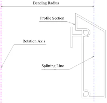
Draw bending of aluminum profiles differs from draw bending of tubes made from steel or other metals in the sense of shape and material properties. Due to the profiles having different shapes (one of the advantages of extrusions), there is no use in developing standardized mandrel and wiper parts. On the other hand, the material properties of aluminum make it many times possible to use plastic tools, and the support can hence be made from plastic rectangular sticks. See Figure 3.6 for an example profile and governing factors for profile bending.
Figure 3.6: Governing factors of the rotary draw bending process of a general section extrusion.
3.4 Existing systems for the automated design of draw
bend-ing toolsets
When it comes to the automation of the design of rotary draw bending toolsets, three different systems have been developed and described in the scientific literature. They are briefly described and commented upon below.
3.4.1 A rule-based system
Abdel-Malek et al presented a work where theories from seamless design to manufac-ture (SDTM) were used to build a system for manufacturability analysis [31]. That work presented an automated system for design-to-manufacture which can perform post-fabrication operations concerning bending and other processes. The system is a rule-based system integrated with a CAD-system (See Figure 3.7). The system enables the automatic design of the toolset assembly and generation of drawings and NC code for appropriate mechanical parts. To make it possible to create and edit rules, a user interface was developed using three different types of “nodes” for dis-playing/retrieving data to/from the user, for performing calculations, and for branch-ing to other “nodes”. The user interface was developed usbranch-ing the development tool
Profile Section
Rotation Axis
Symbologic Adept, the rule base was developed using AutoLisp, and routines for the generation of drawings and the NC-code were developed using the C language. Programmers skilled in AutoLisp and the C language can change the knowledge-base in the described system, having competence in knowledge-based systems. Since the knowledge-base is difficult for humans to interpret, documentation is essential. The same is true for the in-house developed routines.
Figure 3.7: An overview of the system described in [31], from which the picture is taken. 3.4.2 A goal-driven system
Jin et al. described the design automation of toolset for the rotary draw bending, using an object-oriented approach combined with a goal driven inference engine [33]. The objects created to build the knowledge-base were collections of rules as they appear in a rule-based system. Semantic networks were used to describe the objects' internal rule-set. The development language LEVEL5 OBJECTS was used to build the sys-tem. Figure 3.8 shows an example of the internal rule-set of an object for determining whether the final wall thickness will meet product requirements. Figure 3.9 shows how the inference mechanism in LEVEL5 OBJECTS connects different objects.
Figure 3.8: An object consisting of a set of rules described by a semantic net. The system is described in [33], from which the picture is taken.
FRAME OF REFERENCE
Figure 3.9: The system developed by Jin et al was implemented using object-oriented program-ming to build the knowledge-base and user interfaces. The picture is taken from [33].
Since the declarative language LEVEL5 OBJECT was used to implement the know-ledge, changes in the knowledge-base can be done in a straight forward manner by a programmer skilled in that language. Since the objects can be cumbersome to read even to skilled knowledge engineers*, documentation is essential.
3.4.3 A fuzzy logic system
Strano described a system for the automation of toolset design for rotary draw bend-ing [34]. That work presents a system usbend-ing fuzzy logic to select correct tool compo-nents. The system is executed in two steps, where two different knowledge-bases are used. In the first step, calculations are done to get values on variables to feed the knowledge-base used in the second step. The second step is a fuzzy logic system. The approach when building the knowledge-base for the fuzzy logic system was to trans-form all acquired knowledge into decision tables and in which selections are done using production rules (if … then … else). Figure 3.10 shows a section of the rule-block used to select the appropriate type of mandrel. Figure 3.11 shows the structure of the fuzzy logic system. Further, a module for self-learning was added to make the system able to improve its selections.
Figure 3.10: A part of a rule-block implemented in the system developed by [34], from which the picture is taken.
Figure 3.11: An overview of the fuzzy logic system described by Strano [34] , from which the picture is taken.
The system described by Strano is difficult to maintain, since predicting what a change in the knowledge-base would do is not a straightforward task. This is due to two facts. First, it is hard to make global changes when decision tables are used the way they are in the first knowledge-base. Second, the knowledge stored in the fuzzy logic structure (that is actually doing the design proposal) and in the self-learning module is far from human-readable. Making changes in these knowledge-bases is very complicated.
3.5 Identified knowledge gap
The systems reviewed are difficult to maintain due to their complex knowledge-bases or due to the knowledge being transformed into something humans are not able to read. The systems are inflexible and it is hard to edit the knowledge because in such cases major parts of the system need to be changed. This is also true when the targeted design space is extended. None of the systems are able to verify the generated design proposals, and only one manufacturing step is considered. Additionally, it is found that alternative rules can be used for a single problem when reviewing the knowledge used by engineers in the observed development process. Further, the design proposals in the manual process are most often analyzed using the finite element method.
This implies the development of methods for building design automation systems that have a high degree of flexibility, both to edit the underlying knowledge and to extend the targeted design space. The automated design system should also have the ability to select from alternative design rules, be able to simulate and evaluate the production outcome from their own design proposals using FEM, and account for several manu-facturing steps. It is also found valuable to develop methods to utilize such systems to give quick responses to queries early on in the design process.
CHAPTER 4
DESIGN AUTOMATION SYSTEMS WITH A HIGH
DEGREE OF FLEXIBILITY
The complexity of an artifact may be measured in two dimensions – its physical realization and the knowledge required to comprehend it. There are artifacts that cannot be made from a single person, and there are artifacts that cannot be compre-hended by a single person [35]. The former calls for decomposing the product into modules, and the latter calls for dividing the knowledge into chunks. Two ways of achieving flexibility are shown in this chapter. One is by applying object orientation to the knowledge-base. The other is by applying object orientation to the product structure. Finally, guidelines are stated telling when to implement the knowledge using a CAD-integrated KBE-system and when to use a stand-alone KBE- system. This chapter is based on results from appended papers A and B.
4.1 A modular structure of the knowledge-base
Knowledge change over time and a knowledge-base needs to be flexible so that pieces of knowledge can be easily added, updated, or deleted without disrupting the opera-tion of the system. To make a system flexible in that sense, all the parts building it must be autonomous. Hence, to make the knowledge-base flexible, all the chunks of knowledge must be autonomous. A procedural programming approach is not practical in this case, since changing the knowledge-base would mean changing, compiling, and subsequently distributing the programming code. Instead, a declarative way of implementing the knowledge-base has proven to be fruitful.
In a declarative system, the knowledge-base is separated from the functions that make use of the knowledge-base. Consequently, changing the knowledge-base in a declara-tive system can be performed without any changing of programming code.
Since the knowledge that engineers use when designing manufacturing tools is highly connected to various calculations, the use of object-oriented knowledge bases has proven to be successful. The objects are called knowledge objects, and the routine that deals with knowledge objects is called the inference engine.
4.1.1 Knowledge objects
Object-oriented programming offers the possibility to develop highly flexible soft-ware. Objects are closely related to frames. The difference is that a frame is passive in the sense that it does not perform any tasks itself. An object, on the other hand, stores information about itself and performs certain tasks [18].
A class of objects called knowledge objects is proposed (See Figure 4.1). A know-ledge object contains a list of input parameters, a list of output parameters, and a method for processing input parameters to output parameters. Other fields may be added to a knowledge object. Proposed additional fields are constraints, owner, categories, precision, and comments. Owner is used to trace who is responsible for the knowledge object and its method (the task it performs). The field categories can be
DESIGN AUTOMATION SYSTEMS WITH A HIGH DEGREE OF FLEXIBILITY
used to sort knowledge objects into groups. Comments are used to add information usable for explanation extractions and debugging facilities. Finally, the list of con-straints and the precision value is used to allow knowledge-bases to contain alterna-tive knowledge objects (See further in Chapter 5.2.1).
When implementing the knowledge objects, they should be defined in a way that makes them autonomous. Since the methods used to process information preferably are external software applications, the applications should be selected keeping in mind the list of requirements imposed on the design automation system. They are the following: low effort of developing, user readable and understandable knowledge, longevity, and ease of use [8]. The benefits of developing knowledge objects that are autonomous using common wide-spread applications as methods are two-fold: the knowledge can be used manually without the design automation system, and it is easy to find people skilled enough to use the very same knowledge the design automation system does - it makes the knowledge more human-readable (See Section 3.1.2).
Figure 4.1: In the proposed method, the keystone to achieving a high degree of flexibility in design automation systems is a class of objects called knowledge objects.
The anatomy of the knowledge used when designing toolsets for the rotary draw bending implies the use of knowledge objects. Several distinct tasks have been identi-fied and automated using knowledge objects.
4.1.2 Inference engine
An inference engine is needed in order to automate the knowledge stored in the knowledge-base. The inference engine arranges the knowledge in the knowledge-base in an executable order. Two main types of search-based inference engines exist: forward and backward-chaining (See Figure 4.2). A forward-chaining (also called data-driven) mechanism uses the information initially presented to fire all applicable rules. The method has two steps. In the first step, triggered rules are listed. In the second step, an appropriate rule from the triggered ones is selected and fired. After firing the selected rule, all triggered rules are listed again and so on, until no triggered rules are found. If knowledge objects are used to build the knowledge-base, the inference engine searches for knowledge objects with all input parameters known. It then selects one of the found knowledge objects to execute the method defined in that knowledge object to calculate output parameters using the input parameters. When the
Knowledge Object Name Type Precision Cost Inputs Outputs Constraints Implementations Input/Output Name Type Value Comment Constraint Name Type Expression Comment Method Application File Arguments Comment Argument Value
method has run, the stock of known parameters is updated, and a new search for executable knowledge objects is initiated (See Figure 4.3).
Figure 4.2: Two main types of search-based inference engines exist: forward- and backward-chaining.
A backward-chaining mechanism (also called goal-driven) is fed with queries con-cerning which variables to determine. The mechanism then searches backward to see how to end up at that state. When knowledge objects are used, the knowledge-base is searched through to see what objects to fire to find the queried parameters. The user is later asked to put in required information.
The backward-chaining mechanism is more effective at runtime than the forward-chaining one. This is because executions of unnecessary methods are avoided. Since all the design parameters need to be calculated when designing toolsets for the rotary draw bending, the use of a forward-chaining mechanism is suitable.
The knowledge objects communicate with external applications through a connection layer. The connection layer is based on API-dependent routines that can be added in a flexible way.
DESIGN AUTOMATION SYSTEMS WITH A HIGH DEGREE OF FLEXIBILITY 4.1.3 Event-driven inference engines
Event handling is available in today’s operating systems. Here, it is proposed that the inference engine should make use of these advanced functions in the operating sys-tems. That gives an event-based, forward-chaining search mechanism that works as follows. When a parameter is changed, an event is raised in the system notifying that a change has occurred. This triggers an update of the conflict set. If there still are knowledge objects left in the conflict set, one of them is selected to be executed, in accordance with implemented rules for selection. When the object is executed, its output parameters are changed, and the conflict set is updated, and so on (See Figure 4.4). The benefits of using events are the following: when implementing the inference engine, a significant amount of loop algorithms are avoided; when running the sys-tem, the inference engine is triggered automatically on change; and, no extra button clicks are needed (unless functionalities for avoiding automatic updating are imple-mented and activated in the system).
Figure 4.4: Using event handling when implementing an inference engine means that routines are run whenever the knowledge-base is changed.
4.1.4 Global and local automation
To allow design automation systems to have a high degree of flexibility, the proposed method is a modular knowledge representation interpreted by an inference engine. The modules themselves might be local design automation systems, though. A know-ledge module could, for instance, contain an algorithm for finding the shortest path using simulated annealing, and another module could connect to a configuration system getting a product structure. The global design automation system contains local design automation systems. It can be a semi-automatic system containing local islands of fully automated design automation systems connected by graphical user interfaces. The global system can also be a fully automated system containing islands of fully automated design automation systems that are fully integrated. This means that different levels of automation can be achieved. It also means consideration has to be given to what extent and in what steps the design process should be automated and to what cost.
4.1.5 Evaluating the flexibility when using knowledge objects
To evaluate the flexibility when using knowledge objects, a prototype system was developed. The prototype uses the class of knowledge objects, as described in this chapter, and an event-driven, forward-chaining inference engine. The production preparation for rotary draw bending was the application. Since additional features
were added in connection with the other research questions, the prototype system is described in Chapter 5.3.
4.2 Adapting object orientation to the product structure
The other way to achieve a high degree of flexibility in a design automation system is to adapt the object orientation approach to the product structure. Doing so is especial-ly beneficial when appespecial-lying the concept of design automation systems to production toolsets. When it comes to modeling production tools using CAD-integrated KBE-systems, it is difficult to decide where to put the knowledge and the parame-ters/variables. To illustrate this, we can take the example of toolsets for rotary draw bending where some parameter might be needed in several or all of the components. In Figure 4.5, all five bending tool components are shown with associated parameters. It is clear that some parameters appear in several or all of the components. This indicates that coupled relationships exist. In other words, changing the outer tube diameter will affect all components and trigger a sequence of dependent rules and calculations. An object-oriented view of the product is proposed to solve some issues. All components are viewed as objects with attributes (input parameters, in this case). This can be achieved in any parametric CAD-system.
Figure 4.5: All parameters that a single component is associated to are viewed as attributes of objects. Since several parameters can be related to several components, parameter instances are made from the top-level of the product structure to which governing rules are applied.
Form Die: Outer_tube_diameter Form_die_type Compensated_bend_radius Maximal_bend_angle Tool_height Grip_length Clamp Die: Outer_tube_diameter Tool_height Grip_length Mandrel: Outer_tube_diameter Wall_thickness Mandrel_type Pressure/follower Die: Outer_tube_diameter Tool_height Follower_length Wiper: Outer_tube_diameter Compensated_bend_radius Tool_height Grip_length
DESIGN AUTOMATION SYSTEMS WITH A HIGH DEGREE OF FLEXIBILITY
When using the object-oriented view of the components, the parameters are put on an appropriate level in the product structure. In the case of rotary draw bending toolsets, the parameters represented in several components are put at the top level in the product structure (See Figure 4.6). All rules and calculations concerning these top-level parameters are also put at the top of the structure. When changing parameters at top-level, they are passed down to sub-level components, either using connections in the CAD-system or using macro programming (See further Section 3.2 in Appended Paper A). The key idea is to make all the components in the system autonomous, leading to a robust geometric product model where replacement of components without failure is possible.
Figure 4.6: Top-level parameters are inherited by sub-assemblies and components in the product structure. (In the figure, top-level parameters are shown at the bottom.)
4.2.1 Evaluating flexibility when adapting object orientation to the product structure
In order to try the object-oriented approach on the product structure in a CAD-inte-grated KBE-system, a generic geometric model of a toolset for rotary draw bending was created in CATIA and knowledge was added in CATIA/Knowledgeware.
The main idea when building a design automation system for rotary draw bending in CATIA/Knowledgeware was to use the internal programming language to build methods executing external software applications to calculate different design va-riables (similar to the approach described in Chapter 4.1.1). The system contains methods for executing spread sheets to select correct types of components, material data, and bending machines. It also includes methods for executing algorithmic programs to calculate developed length, minimal wall thickness after bending, angular
spring back, and section modulus. Some factors were calculated using functionalities in CATIA/Knowledgeware.
The knowledge implemented in the CATIA\Knowledgeware system are heuristic rules and rules analytically derived from fundamental physical laws as found in the literature, and from interviewing draw bending experts. More details are found in Appended Paper A. Examples of specialist knowledge used in the applications are presented in the Appendix B. Figure 4.7 shows two examples of output.
Parameter Example 1 Example 2
Outer_tube_diameter 45 mm 60 mm
Tube_wall_thickness 5 mm 2 mm
Wanted_bending_angle 180° 180°
Section_modulus 4.74 cm3 3.965 cm3
Tube_material Sapa 6063-T4 Sapa 6063-T4
Wanted_bendradius 80 mm 80 mm
Results Heuristic Analytic Heuristic Analytic
Mandrel_type Plug N/A* Regular Pitch N/A*
Bending_moment 434 Nm 618Nm 363 Nm 584Nm
Minimal_wall_thickness 3.9 mm 4.3mm 1.5 mm 1.6mm
Developed_length 251mm 239mm 251mm 228mm
Figure 4.7: Two examples of output from the prototype system. Total time to configure a tool-set-up is a few minutes, where most of the time is spent typing in parameter values. In the heuristic rules, different factors are used when mandrel types are changed (1.3 for plug and 1.6 for mandrel). (*Was not implemented)
4.3 Stand-alone and CAD-integrated KBE-systems
It is possible to implement the knowledge-base in stand-alone KBE-systems or into integrated KBE-systems. In Figure 4.8, an implementation using a CAD-integrated KBE-system is shown. Figure 4.9 shows a KBE-system that is stand-alone and that connects to a CAD-system when a geometric representation is needed.
When using a CAD-integrated KBE-system to implement the knowledge-base, the rules will be listed in the model-tree among the different features. This can be valua-ble since it is easy to see what geometries the rules are connected to. It also makes the user feel familiar with the user interface. But the knowledge-base in such a system will be cumbersome to understand when the knowledge-base contains a vast number of rules compared to the number of geometry features. This is especially true if many of the rules do not deal with geometry. If this is the case, a stand-alone KBE-system should be used.
Another issue to consider is that when using a CAD-integrated KBE-system, the knowledge is bound to the CAD-system. This means the knowledge-base will be difficult to translate to other CAD-systems. In stand-alone KBE-systems, knowledge
DESIGN AUTOMATION SYSTEMS WITH A HIGH DEGREE OF FLEXIBILITY
is managed and design proposals can be generated in native or neutral CAD-formats. It can be hard to implement a knowledge-base containing mostly geometric relation-ships into a stand-alone KBE-system, though. In Figure 4.10, an overview of when to use a CAD-integrated or a stand-alone KBE-system is presented. One benefit of the stand-alone KBE is the distinct interface between CAD and KBE. It is usually a set of parameters, and it helps clarify which parameters the governing ones of the design are.
Figure 4.8: To evaluate the flexibility when using a CAD-integrated KBE-system, CATIA was used to create a generic model of a toolset for rotary draw bending. Knowledge was added to that model using CATIA\Knowledgeware.
Figure 4.9: To evaluate the flexibility when a stand-alone KBE-system is employed, an inference engine was developed that allowed the use of knowledge objects.
Embedded formulas
Excel-sheets
MathCAD-sheets Any external program
f(x)=ax +bx+c2 CAD-system CAD-system δ1 0 π 2 α 2 π cosα( ) 2 k 2 k+3−2 cos( )α 4 k+1+cos( )α 8 8 8 888 8 8 8 d := d 1−δ1 δ2+2 8 8 8 8 8 8=0.079 m MathCAD-sheets Stand-alone KBE application
Stand-alone KBE application
Bendingtool Wall_thickness Radial_Springback Angular_Springback Developed_length Type Inputs Output Implementation Spread-sheets Algorithmic programs
Figure 4.10: A stand-alone KBE-system is proposed when the number of geometrical relation-ships compared to the total number of rules in the knowledge-base is low and when the number of geometry features compared to the total number of rules is low. Otherwise, a CAD-integrated system is suitable for the implementation of the knowledge-base.
CAD-integrated KBE-systems proposed Stand-alone KBE-systems proposed Geo m et ri c re la tions hi ps / N umbe r of r ul es 0 1 0 1
CHAPTER 5
KNOWLEDGE-BASES CONTAINING
ALTERNATIVE DESIGN RULES
Often, several sources of knowledge exist, and sometimes there are interferences between these sources. Developing methods for handling such situations will make the design automation systems more adaptable to different situations. This chapter shows how such interferences in a knowledge-base might occur and presents a proposal for how to solve these situations. Finally, a prototype system is described.
This chapter is based on results from append paper B and it forms a basis for the subsequent chapters.
5.1 Different sources of knowledge and meta-knowledge
In the scope of metal forming processes, it is often possible to calculate a single vari-able in different ways. Sometimes a heuristic rule can be used, or rules analytically derived from the fundamental laws of physics. But it is also possible to do FEM-calculations or experiments to evaluate a design variable. In addition to these four types of knowledge, an engineer also needs to have the capability to decide when to use what knowledge; this is called meta-knowledge, or knowledge about knowledge. When more than one type of knowledge source is available in a knowledge-base, the question of when to use what source arises. In one state, the system may be executed in order to make a quotation calculation with only a small set of input parameters available. In the next step, detailed design is the purpose of running the system, with high accuracy as the main focus and with a larger set of input parameters available. Different kinds of knowledge are used in these different contexts, and implementing meta-knowledge would allow for the flexible use of the system. A description of the different types of knowledge is presented below.
5.1.1 Rules of thumb, heuristics
Heuristics is generally found in different handbooks or company standards and is based on skilled engineers' experiences. Usually they are easy-to-use relationships that are valid for a small range in the design space. Heuristic rules seldom explain why things happen. The benefit of heuristics is that they have often proven to be correct enough and that they enable fast computer implementations. In reality, many design processes and design automation systems are built on this kind of knowledge.
5.1.2 Knowledge analytically derived from the fundamental laws of physics
Rules analytically derived from the fundamental laws of physics tend to be more complex than heuristics. However, they have the benefit of explaining why things happen and are more general. One benefit of analytical rules is that they are fast to execute when finally implemented in a computer system. Even though analytical rules are built on fundamental physical laws, they still are idealizations of complex prob-lems.
KNOWLEDGE-BASES CONTAINING ALTERNATIVE DESIGN RULES
In many situations, it is not economical or even possible to develop analytical expres-sions. In such cases, numerical methods might be utilized or experiments can be performed.
5.1.3 Finite element analysis
A number of numerical methods exist for solving different engineering problems. Probably the most common method is the finite element method (FEM). FEM can be used to solve many engineering problems. However, the results depend greatly on what assumptions are made in the simulations.
Using FEM appropriately will give highly reliable data. The drawback is that, com-pared to heuristic and analytical knowledge, FEM is costly to use both in money, competence, and time. In addition, it does not explicitly answer the question of why things happen. The benefit of FEM, however, is that it allows full control over the process so it is easy to scroll in time and space, doing sections and plotting different parameters.
Worth mentioning in this context is that simulation-tools are comparable to instru-ments for measureinstru-ments (in other words, they must be calibrated). This calibration is done via result feedback. Over time an accurate model is developed.
5.1.4 Experimental data
Reality is the truth. Thus, making trial manufacturing will give reliable data. The drawback is that experiments are expensive, have limited range, and do not answer the question of why things happen. To make empirical data usable, experiment planning has to be done beforehand to isolate targeted parameters.
5.2 Enabling knowledge adaptability
In this section, a proposal is made regarding how to solve the situation of when multiple sources of knowledge co-exist for a single phenomenon. The proposal is based on the extension of the knowledge objects and the usage of a global parameter list within the system.
5.2.1 Extending the knowledge objects
In Section 4.1.1, knowledge objects were introduced to represent the knowledge in the knowledge-base. A list of constraints and a precision value need to be added to the knowledge object class in order to make it possible to have multiple knowledge objects pointing to the same parameter in the knowledge-base. The constraints dictate when the knowledge object is applicable, and the precision value tells how good the outputs are. The precision value ranges between 0 and 1 and might be changed in the design space.
5.2.2 A global parameter list
Knowledge objects use external applications as methods. To pass information to the external applications, meta-data is needed (not to be confused with meta-knowledge). That meta-data is locally stored within the knowledge objects. The calculated parame-ter values are stored in a global list of parameparame-ters.
Such a system can be described as a classroom with experts in draw bending tool design (the knowledge objects). All the experts have a specific task and watch the whiteboard (the global list of parameters). In addition, they have their own pieces of paper to carry out their own calculations. The expert might name parameters diffe-rently on their papers (meta-data). Whenever an expert can see enough information on the whiteboard to solve his/her task, he/she will ask the moderator (the inference engine) to be allowed to calculate some of the unknowns on the whiteboard. Based on opinions (meta-knowledge) about the expert, the expert might be refused. If approved to perform the calculation, the expert will write the new information on the white-board when finished, which might cause other experts to ask the moderator to com-plete their task.
Figure 5.1: The knowledge objects can be viewed as experts, the inference engine as a moderator, and the global list as a whiteboard.
5.2.3 Knowledge adaptability
When a knowledge object writes a value to a parameter, the precision value of that knowledge object can be stored together with the parameter in the global list. That will make a history of what precision a parameter value has. A rule is proposed saying that a knowledge object may only overwrite a parameter if its precision value is strictly bigger than the current precision value of that parameter in the global para-meter list. When using constraints together with precision values in the global list, the system will run in the following sequence:
Do until the conflict set is empty:
1. List all triggered objects not violating any constraints, exclude solved objects. Sort the list by precision.
2. Execute the knowledge object with highest precision (“first come, first served” if several objects with the same precision exist).
3. Clear all output parameters in knowledge objects dependent on the outputs from the fired knowledge object. This can cause rules to fire more than once, but is done to make sure that the output with the highest precision is the final result.
![Figure 1.1: The Design For Manufacturability approach according to [5]. The research pre- pre-sented in this thesis has concerned the dashed connections and concepts, of which computer-aided analysis was added to the manufacturing requirement in the origi](https://thumb-eu.123doks.com/thumbv2/5dokorg/5404866.138519/14.892.178.718.116.567/manufacturability-approach-according-research-concerned-connections-manufacturing-requirement.webp)

![Figure 2.2: The applied research method was adapted from Roozenburg and Eekels [12].](https://thumb-eu.123doks.com/thumbv2/5dokorg/5404866.138519/21.892.265.687.125.843/figure-applied-research-method-adapted-roozenburg-eekels.webp)
![Figure 3.1: A categorization of the intelligent systems as presented in [18]. The knowledge-based systems category is a big share of the intelligent system domain and is broken down into several sub-domains](https://thumb-eu.123doks.com/thumbv2/5dokorg/5404866.138519/24.892.229.667.125.498/figure-categorization-intelligent-systems-presented-knowledge-category-intelligent.webp)


![Figure 3.11: An overview of the fuzzy logic system described by Strano [34] , from which the picture is taken](https://thumb-eu.123doks.com/thumbv2/5dokorg/5404866.138519/31.892.304.618.126.413/figure-overview-fuzzy-logic-described-strano-picture-taken.webp)

