V¨
aster˚
as, Sweden
Thesis for the Degree of Master of Science in Computer Science
-Embbedded systems 15.0 credits
A COMPARISON FRAMEWORK FOR
THE VEHICULAR MODELING
LANGUAGES ON ENABLING
PRE-RUNTIME TIMING ANALYSIS
Igli Jasharllari
iji19001@student.mdh.se
Examiner: Saad Mubeen
M¨
alardalen University, V¨
aster˚
as, Sweden
Supervisors: Alessio Bucaioni
M¨
alardalen University, V¨
aster˚
as, Sweden
Mohammad Ashjaei
M¨
alardalen University, V¨
aster˚
as, Sweden
Abstract
Handling the software complexity of modern vehicle functionalities has become very challenging due to their non-centralized nature and real-time requirements that they impose. These functionalities are usually developed as distributed real-time embedded systems composed of several nodes (Elec-tronic Control Unit) and multiple communication protocols. Among many software development paradigms for these systems, the model-based approach excels mainly for two reasons. First, it handles the software complexity by separation of concerns through the use of models. Second, it en-sures the timing predictability of these systems by adopting the timing analysis techniques proposed by the research community. They are pre-runtime timing analysis techniques that provide shreds of evidence whether all the timing requirements will be met during the execution of the system. In this thesis work, we propose a comprehensive framework that captures the timing related information needed for the modeling languages to facilitate these timing analyses. The framework is compre-hensive in such a way that it identifies the generic timing properties for the nodes and network respectively. What is more, the system’s timing model generated by the modeling languages requires tool support for extracting and interpreting this information. Hence, we validate the applicability of the framework by comparing two modeling languages and their respective tool-chains such as Rubus-ICE and APP4MC used in the vehicular industry.
Table of Contents
1 Introduction 1 1.1 Problem Formulation . . . 2 1.2 Thesis Contribution . . . 2 1.3 Thesis outline . . . 2 2 Background 3 2.1 Embedded systems . . . 32.2 Real-time Embedded systems . . . 3
2.3 Real-time distributed Embedded systems . . . 4
2.3.1 Real-time scheduling algorithms and policies . . . 4
2.3.2 Timing Analysis . . . 5
2.4 Model-based development and software engineering of automotive systems . . . 7
3 Related Work 8 4 Research Method 9 5 The Comparison Framework 10 5.1 Timing Model . . . 10
5.1.1 Timing Properties . . . 10
5.1.2 Timing Requirements . . . 12
5.2 Timing Verification . . . 15
6 Case Study 16 6.1 Rubus Component Model . . . 16
6.2 Amalthea model and APP4MC . . . 16
6.3 Timing Model . . . 17 6.4 Timing Constraints . . . 19 6.5 Timing Verification . . . 21 7 Conclusions 23 8 Future Work 24 9 Acknowledgments 25 References 30
1
Introduction
Over the last decades, the development of automotive embedded software has faced several chal-lenges related to its size and quality [1]. Modern vehicles employ software systems composed of more than 100 million lines of code running on more than 100 Electronic Control Units (ECUs) [2]. What is more, modern Advanced Driver Assistance Systems (ADASs) as, e.g., pedestrian protec-tion system, autonomous parking system, impose strict quality requirements such as safety and timing requirements. Accordingly, vehicle functionalities not only need to be correct, but they must be performed in a timely manner hence at a time that is suitable for the environment they interact with [3].
To cope with the increasing complexity of automotive software and its development, researchers and practitioners have successfully adopted emerging software development paradigms including model-based software development [4]. Model-based software development promotes abstraction and separation of concerns principles through the use of models. Models are artifacts which provide for focused representations of the system under development by highlighting relevant information while abstracting less relevant one [5]. The adoption of this approach concedes for a flexible and more automated development process. Hence, giving several benefits such as early revealing of design flaws, automatic code generation, and overall development costs minimization. In particu-lar, it provides means that can serve as the basis for timing verification during the development. For example, the definition of timing properties and requirements for the tasks and messages that compose the application. This is crucial in the automotive industry where the objective is to have available timing-related information and shreds of evidence that guarantee the system timing pre-dictability as soon as possible [6]. If these pieces of evidence prove that all the timing requirements will be satisfied during the run time, then the system is considered as time predictable [7].
The software timing verification is performed using different timing analysis techniques [8], [9], [10]. In recent years, several modeling languages and methodologies supporting timing analyses have been defined [11], e.g., the Rubus Component Model (RCM) [12], Amalthea [13]. Despite several languages support the timing analysis of automotive software, they are characterized by different approaches towards the modeling of timing related information, hence having different expressiveness on timing properties and constraints. For instance, the real time properties such as deadlines, period jitter and offset of the application tasks are linked with properties of Software Circuits (SWC, basic unit of RCM hierarchical elements) [12]. In Amalthea, the real time properties are distributed among 3 different elements called task, stimuli and runnable [13]. The abstraction level in describing the development of the embedded software is higher in Amalthea. For instance, a RCM SWC could be paralleled more with the Runnable entity which is only a part of the Amalthea SWCs. To this end, the languages have different levels of expressiveness in supporting the modeling of timing information. As a result, the timing information that a timing analysis tool requires as an input may be partially or fully extract-able from the software architectures that are modeled with the languages. Consequently, timing analysis of the software architectures that are modeled with the languages that have limited expressiveness for timing information cannot be supported without making over-estimated assumptions.
To date, few researches have focused on characterizing and comparing modeling languages with respect to timing perspective as most of them focus on other extra-functional requirements. In this context, it would be beneficial to both researchers and practitioners to have means for classifying and categorizing modeling languages with respect to timing support. Based on such a classifica-tion, one could easily identify which of the modeling languages would be more appropriate for a specific application. For example, distributed applications which require nodes to communicate with different real-time protocols, applications which require particular functionalities to run in parallel or with precedence relations, functionalities developed with multi-rate or single-rate trans-actions. What is more, the framework could establish a basis for the timing modeling capabilities comparison of the languages.
1.1
Problem Formulation
A real-time embedded system application might be described by different timing constraints, differ-ent tasks activation patterns and differdiffer-ent target architectures. In the literature, numerous state-of-the-art timing analysis methods have been introduced for considering such various scenarios. They have also been implemented in either commercial or academic tools and engines. However, their applicability is highly dependent on the level of timing information extracted by the timing model composed by a particular modeling language. Hence, given the problem of categorizing and comparing different modeling languages based on the timing information and analyses they enable, in this thesis, we address the following Research Problem (RP):
RP How can we categorize and compare modeling languages based on a theoretical framework considering their timing expressiveness?
Starting from the above-mentioned RP, we foresee the following Research Challenges (RCs): RC1 Which are the timing properties and related information for categorizing and comparing
different modeling languages with respect to various types of timing analysis that they enable? RC2 Can we use the framework for characterising and comparing two languages being Amalthea
and RCM?
1.2
Thesis Contribution
The main contribution of this thesis work is to develop a comprehensive framework for charac-terising modeling languages supporting timing analysis. In order to show the applicability of the proposed framework, we will use the framework for categorizing two industrial modelling languages widely used in the automotive domain being the Rubus Component Model [12] and Amalthea [13] and their respective tool-chains Rubus-ICE [14] and APP4MC [15].
1.3
Thesis outline
The rest of the thesis is organized as follows: Section 2 introduces concepts and definitions needed to understand the work presented in this thesis. In Section 3 state-of-the-art research and related work is investigated. Section 4 describes the research method accommodated and followed for achieving the objective of the thesis. In Section 5 we present the classification framework as the main contribution of this work. A case study validating the proposed framework is discussed in Section 6. Finally, in Section 7 and 8 conclusions and future work are discussed.
2
Background
2.1
Embedded systems
Every day we are surrounded by thousands of ’undercover’ computers working silently to make our life easier. Unlike the general-purpose computers like a laptop, they are hidden inside the applications that they control or are part of, e.g., an automatic coffee machine. These computers are known as embedded systems and are microprocessor-based systems constructed to perform dedicated functions [16]. Embedded systems are usually integrated into larger systems and interact with the outer environment via sensors and actuators. In particular, actuators apply the output which is produced by processing the information coming from the sensors according to the software instructions flashed in its memory. In many application domains, the size and complexity of the software operating embedded systems have drastically increased due to the advanced functionalities these systems are expected to provide [1]. An example of this comes from the automotive domain. According to a recent study from Jaguar Land Rover [17], the size of the the software running in the embedded systems used for realising autonomous vehicles will soon reach 1 billion lines of code.
2.2
Real-time Embedded systems
Often embedded systems must comply to timing requirements meaning that, for delivering a cor-rect functionality, they must produce the corcor-rect behavior within a given time often known as deadline [18]. These embedded systems are known as real-time embedded systems. According to the tolerance allowed in missing the deadline, real-time embedded systems can be divided into two types: soft real-time embedded systems and hard real-time embedded systems. The result of the former is considered acceptable even though an occasional deadline is missed within a tolerable margin. Hard real-time embedded systems, instead, have zero-tolerance on missing the specified deadline as failing to meet it might result in the system failure that could cause severe damages to the humans or the environment. Examples of soft and hard real-time embedded systems from the automotive domain are the in-vehicle infotainment and airbag systems, respectively.
Usually, the function that an embedded system is required to produce is accomplished by a set of tasks. A task is defined as a software routine programmed to perform a particular func-tion [18]. Real-time tasks are characterized by several parameters and timing constraints. The main parameters and constraints [18]:
• Arrival time is the point in time when the task instance gets ready to be executed. • Worst case execution time (WCET) is the time needed for the CPU to execute the task
without any interference or interruptions.
• Start time is the point in time when the task starts to be executed. If no interference or preemption are experienced by the task, then this time is equal to the arrival time.
• Finishing time is the point in time when the task finishes its execution.
• Response time is defined as the time between the arrival and finishing time of the task. • Absolute Deadline - Deadline when it is specified according to the zero time of the system. • Offset is the time interval between the start of the period and the arrival time of the task. • Period is the time interval between two successive arrivals of task instances.
• Jitter is the execution time variations of tasks caused by high priority task interference. Based on the inter-arrival times of tasks instances, we can have different kind of tasks. Periodic tasks are those tasks for which the inter-arrival time if fixed and known. Sporadic tasks have only the minimum inter-arrival time fixed and known(but not the exact arrival time of the next task instance). Aperiodic tasks have the worst execution time and deadline constraints known, but not their period.
2.3
Real-time distributed Embedded systems
In many domains, embedded systems applications are developed by using non-decentralized ar-chitectures. The overall application functionality is distributed among several nodes that are interconnected by one or more communication networks [19]. Each node is a sub-system dedicated to specific functionalities. In the vehicular domain, a node is often known as Electronic Control Unit (ECU).
Nodes and the network have an impact on the overall system performance in terms of power consumption, reliability, scalability and timing behavior [19]. The timing requirements on the information that should be delivered from one end to the other end of the network dictate the timing behavior. This information is usually encapsulated and transmitted as message frames through the network. The properties of such message frames are different and determined by the communication protocols. However, the real-time communication can be divided into two main categories based on the communication triggering method [20], as follows.
• Time-Triggered. Nodes are synchronized and operate based on a common clock refer-ence. Messages can be transmitted at fixed points in time following a predefined schedule developed in advance. This enables the designer to ensure low collision rate communication. This method is preferred for functionalities where periodicity matters such as periodic data acquisition and actuation.
• Event-Triggered. Nodes deliver messages based on signals coming from the occurrence of different events. For instance, a node might put a message for transmission upon the moment it receives an interrupt signal from a task which finished its execution. This method is more suitable for functionalities with sporadic nature.
In some applications, a combination of both methods is used to ensure the timing correctness and guarantee the desired results. In literature, many real-time communication protocols based on these techniques have been proposed [21].
There exist some similarities between the network and nodes regarding the timing behavior. Messages and tasks might share similar activation patterns, similar scheduling policies, or analogous scheduling analyses [22]. They are discussed in details in Section 2.3.1. Despite these similarities, differences are also present. For example, the network scheduler takes decisions based on a lack of full-timing information in some cases [23]. What is more, messages are fragmented in packets. The transmission of the packets via the communication link is usually non-preemptable. However, interrupts can be present in message level [22].
2.3.1 Real-time scheduling algorithms and policies
Besides timing constrains, real-time tasks are usually characterized by mutual exclusion constraints and precedence relations [18]. As a consequence, developing a feasible schedule for tasks to meet the deadlines and other constraints is not a trivial assignment.
Time-driven and Priority-driven Scheduling
In the literature, many scheduling algorithms have been proposed [18]. Offline and online real-time scheduling algorithms are the two fundamental categories where these algorithms fit in. Offline scheduling manages the tasks according to a pre-defined schedule constructed before the system start. Online scheduling also known as priority-driven scheduling takes run-time decisions about which task is going to be executed and when. The task priority indicates the importance of a functionality in a particular application. Task priorities assigned before run-time and not changed in the meantime is a property of fixed-priority online scheduling. Alternatively, when task pri-orities change it is considered dynamic online scheduling. A classical example of static priority scheduling is the Rate-Monotonic(RM) algorithm [24] while the Earliest deadline first (EDF) [18] is a dynamic online scheduling algorithm. What is more, tasks can experience preemptions due to several reasons e.g., allowing a higher priority task to execute when it becomes ready. Hence, the system is considered as a pre-emptive system. In contrary, when a task is not allowed to be interrupted in the middle of its execution the system is called non-preemptable.
Share-driven scheduling
Another alternative scheduling technique based on the principle of allocating a fraction of a re-source to a task is presented in paper [25]. Share of the resource is usually provided by servers. A server is a periodic or sporadic task responsible for handling aperiodic tasks execution requests. The main objective is to reduce the aperiodic task average response time. In literature, many server types have been introduced. Most common ones for dynamic-priority category of systems are Constant Bandwidth Servers(CBS) and Total Bandwidth Servers, while for static-priority are Sporadic Servers, Polling Servers and Deferrable servers [26].
Multi-core scheduling algorithms
The demand for more computing power, less power consumption and single-core physical limi-tations led processor engineers to switch to multi-core architectures [27]. Ensuring the real-time performance while getting the most out of this enhanced power dictates the need for effective scheduling algorithms aided by solid schedulability analysis methods. Two of the most common scheduling techniques are described in the following section.
Partitioned scheduling is one of the main multi-core scheduling approaches where each core has its task queue and scheduler. Tasks are pre-assigned before run-time to one of the cores and are not allowed to migrate. Single-core scheduling algorithms can also be used, but allocating tasks to cores is not trivial. Global scheduling, contains only one global task queue and scheduler for all the cores. Tasks are assigned to cores based on scheduler decisions made during run time. A detailed survey on multi-core scheduling algorithms is presented by Davies et al [28].
2.3.2 Timing Analysis
Real-time embedded systems correctness does not depend only on correct functionality, but on timing correctness, too. The reliability and timing predictability of these systems must be ensured via trustful pieces of evidence. There exist different approaches in the literature concerning this problem. One approach to providing the timing evidence is the schedulability analysis based on the CPU utilization factor. CPU utilization factor is defined as the time needed for the processor to execute all tasks of a task set. For a comprehensive overview of utilization-based tests, the reader might refer to [29]. The demand-based test is another approach that indicates how much computation time a task set requests for an arbitrary amount of time [30] [31] However, these tests give no information about the task response times.
Response-time analysis
An alternative approach is to iteratively calculate the worst-case execution time of tasks or mes-sages and compare them with the respective deadlines. This technique is referred to as Response Time Analysis(RTA) and the theoretical foundation was set by Liu & Layland for systems sched-uled by fixed-priority algorithm policies [32]. Interference which might come from higher priority tasks is also considered. During recent years, it has been extended by the researchers to increase the test precision and its ability to analyze complicated system behaviors [33] [34] [35] [36]. As we previously discussed, the same algorithms can be applied to network messages. Hence, similar response time calculation techniques are used. However, the calculation of blocking and inter-ference is calculated based on protocol-specific characteristics. For instance, different worst-case response times have been presented, RTA for CAN messages [37], RTA for mixed CAN messages with FIFO and priority queues [38] [39] [40] [41], RTA for mixed CAN messages with offsets and priority-ordered queues [42], RTA for FlexRay messages [43], RTA for AVB Ethernet messages [44], RTA for Switched Ethernet messages [45].
End-to-end timing analysis
Many real-time applications are modeled with data chains, trigger chains, or a mix of both [46]. However, timing requirements on these chains are different. For instance, we are interested in the end-to-end or holistic response time of the trigger chain. They calculate the time between the
trigger of an event and the finishing response time of the last task in the chain [47]. These event-chains might also be distributed among several nodes e.g., response-time of the task responsible for the actuation signal on the engine corresponding to the input coming from throttle pedal in the sensor node. System schedulability is ensured when all the holistic response times of trigger chains are less or equal to the respective deadlines.
Figure 1: Chain activation patterns a) Event-triggered b) Time-triggered
In multi-rate chains, holistic response time does not give a complete timing behavior of the system that is modeled. This is due to the fact that tasks are activated independently and in most cases with different properties e.g, different periods [46]. What is more, we might have inputs that may have not a corresponding output or duplicate outputs corresponding to a single input due to data transmitted between tasks and messages are exchanged using non-consuming buffers. Hence, comparing the holistic response time with the corresponding chain deadline does not give a complete complete information about timing predictability of the chain. In the automotive domain, most requirements on data chains are focused on the first reaction to input or the age of the data obtained at the output [8].
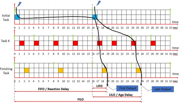
Figure 2 illustrates a multi-rate real-time system modeled with trigger chains. Tasks are activated independently with periods 16, 4, 8 respectively and WCET 1 time units. The task set can be seen as a functionality in a node where the initial task reads data from a particular sensor while finishing task provides the actuating signal.
Figure 2: Data chain delays
• Last In First Out (LIFO). The delay between the current release of initial task that is not overwritten and the first corresponding response of the finishing task
• Last In Last Out (LILO). The delay between the current release of initial task that is not overwritten and the last corresponding response of the finishing task. It is also known as data age and is crucial for control systems where the actuating signal should not surpass a maximum age [8].
• First in First out (FIFO). The delay between the previous release of the initial task that is not overwritten and the first corresponding response of the finishing task to the current release of the initial task that is not overwritten. It should be noted that here ”just miss” effect is taken into consideration. Assume that a new input value is in the initial task buffer just after the release of the task, this input would be missed and it should wait for the next task instances to be consumed. For example, first output corresponding to input coming at 4 time appears at 17 which makes it a 13 time units delay. It is also known as Data Reaction Delay and is important for applications where first reaction to input is valuable [8].
• First in Last out (FILO). The delay between the previous release of the initial task that is not overwritten and the last corresponding response of the finishing task to the current release of the initial task that is not overwritten. ”Just miss” effect is also considered here.
Data chains might also be distributed among several nodes in distributed real-time embed-ded system applications. However, end-to-end delays are formulated similarly due to the similar activation patterns of tasks with those of single-node systems. [46].
2.4
Model-based development and software engineering of automotive
systems
As vehicles transition from being mechanical-based to software-driven systems, the complexity of automotive software systems is constantly increasing. Many techniques have been developed to overcome the problem of designing and developing complex software systems including Model-based Software Engineering (MBSE) [48].
Model-based Software Engineering focuses on raising the abstraction of software development by using models rather than code [49]. Models represent an abstraction of the system which highlights the characteristics of interest and hides the non-relevant ones. For example, the modeling of the system timing behavior while the hardware-specific details are hidden. In this paradigm, the system is developed through constant model manipulation until no more refinements appear obtainable [49]. Then automatic code is generated. Despite handling software complexity, it also offers many advantages such as reducing time to market and development costs or increasing the scalability and flexibility of the software.
There exist many modeling languages such as SysML [50], AADL [51] that also support the modeling of timing information, but this thesis work focuses mainly on developing a comprehensive classifying framework for the automotive modeling languages such as Rubus Component Model (RCM) [12], Amalthea [13]. Moreover, the tools supporting these modeling languages concerning timing analysis will also be discussed.
3
Related Work
There have been numerous studies investigating differences and similarities between different mod-eling languages and tools supporting the timing analysis.
The research conducted in [11] and [52] present an overview of the current modeling languages and their respective tool support in the vehicular domain. A comprehensive description regarding the timing modeling and timing analysis is given. The modeling languages and tools are grouped based on the four levels of abstractions for vehicular embedded systems development. Although we also target the vehicular modeling languages in this thesis work, we aim to compare the languages based on their timing-related information comprehensiveness and timing analysis they enable. What is more we aim to establish a comparison framework for the existing languages and those that will arise in the future.
A framework for comparing real-time modeling languages based on different aspects is presented in [53]. For example, the scope of modeling languages argues that if either they are suitable for system engineering in general or embedded real-time software. Because the modeling languages have often different semantics, the formalism aspect contributes in clarifying these differences. Moreover, architectural coverage is thoroughly discussed. Two other comparison characteristics are the extension capabilities and tool support. Despite we believe that these properties are very important when choosing a modeling language, in this thesis we aim to develop a comprehensive framework with in-depth investigation of their capability for describing the timing behavior of real-time systems.
Another classification and comparison framework developed in [54] takes into consideration mainly the functional, but also non functional aspects of the modeling languages. However it focuses only in Architecture Description Languages(ADLs). It aims to give an answer on which aspects of the architecture should be modeled by an ADL and which of many ADL languages is the best for a particular problem. An extended version of framework presented above was developed in paper [55]. The author added several features of hardware architectures and non-functional characteristics such as timing and dependability typical for safety-critical software-intensive systems. Even though the framework is extended, timing aspect is not the primary focus. As a consequence with this thesis work, we focus on filling this gap by providing the minimal criteria for a modeling language to describe the timing behavior of a real time system and enable their timing analysis.
In [56] Crnkovi´c et. al present a survey of component-based modeling languages and a clas-sification framework. Authors identify the minimal criteria for these modeling languages to be considered as component-based. This is done by not including technology-specific unique solution elements. Specific-domain modeling languages in different domains are taken in consideration. This goes beyond the scope of our thesis as we are trying to classify and compare modeling languages regarding timing behavior description and analysis in the vehicular domain only.
Similarly, the work conducted in paper [57] goes a little further as it puts in comparison the whole tool chain based on the AADL and EVENT-B modeling languages. The latter followed by the supporting synthesis and analysis tools should be featured to a particular extent level. Although the framework gives a complete detailed overview of component, connectors, architectural configuration modeling and tool support, but not to the same degree non-functional requirements information, e.g, timing. However, in our work we focus on developing a framework without considering the modeling languages solutions for being able to provide the timing information.
The work in [58] drew our attention because a set of features and capabilities are defined with respect to timing analysis. Modeling languages should satisfy such system and design oriented features in order to enable timing analysis. If so, this timing analysis can be done in different abstraction levels and with an adequate precision, the authors believe. Although this is closer to our thesis work scope, we still need means to further evaluate the modeling languages who support the timing analysis. Moreover, the accompanying tools and their capability of supporting what modeling languages can express should also be investigated. The latter is what we also aim to provide as a part of our thesis work contribution.
In particular no study, to the best of our knowledge, has considered for categorising and compar-ing vehicular modelcompar-ing languages based on timcompar-ing expressiveness which is responsible for enablcompar-ing timing analyses with different characteristics such as efficiency and precision.
4
Research Method
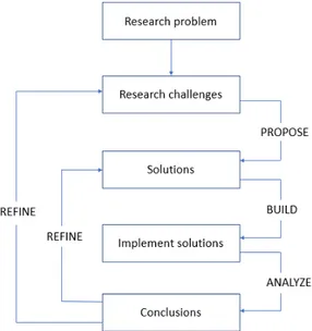
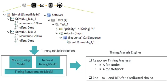
In this thesis, we have followed a research method which is and adaptation of the engineering method proposed in paper [59] defined as ”observe existing solutions, propose better solutions, build/develop, measure and analyze, and repeat the process until no more improvements appear possible”. Figure 3 provides for a graphical representation of the adopted research method. We have started from investigating the problem of classifying and comparing modelling languages based on their support to timing and timing analysis. Such an investigation has helped us in defining concrete research challenges and in providing insights on already documented similar approaches, their strengths and weakness.
Figure 3: Research methodology
For each elicited research challenge, we have performed an exhaustive study of the state-of-the-art and the state-of-the-practice related work attempting to come with a potential solution in case none already existed. After a solution was developed, we have evaluated its applicability on use cases. Based on the results of the evaluation, the proposed solution could be refined. This is the case of the framework, which has been refined several times prior to its final version. What is more, we have used the findings acquired during the elicitation, implementation and evaluation for the solution for adding or updating a research challenge. This was the case of RC2, which was added as a way of validating the proposed framework.
5
The Comparison Framework
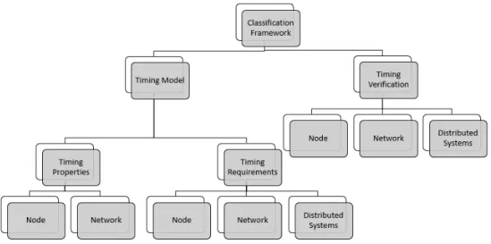
Most of the automotive functionalities are developed using non-centralized architectures with real-time safety requirements e.g ISO 26262 - 1: 2018 - (Road vehicles - Functional Safety Standard [60]). Researchers have developed pre-run time analyses for providing evidence that these functionalities comply with their timing requirements. A pre-run time analysis is performed at the design time prior to running the system. Usually, these analyses are enabled and supported by modeling lan-guages and accompanying tools. Modeling lanlan-guages allow specifying the software architecture and real-time information of automotive functionalities. Accompanying tools interpret the information specified using the modeling languages and execute the algorithms of pre-run time analyses. Differ-ent modeling languages might support differDiffer-ent timing properties and pre-run time analyses while having different tool support. In the following section, we describe a framework, which can be used for categorizing and comparing different modeling languages based on their timing expressiveness. The framework is graphically illustrated in Figure. 4.
Figure 4: Classification Framework
• Timing Model contains all the real-time properties and requirements concerning the overall timing behavior of the system.
– Timing Properties contains the real-time properties of nodes and network communi-cations.
– Timing Requirements contains real-time requirements expressed on the timing model. • Timing Verification contains the techniques for validating the timing requirements on the
timing model.
5.1
Timing Model
Modeling languages help in building a timing model that serves as an input for the timing analysis engine. In real-time distributed embedded systems, the timing model of the system should consist of timing-related information of each node and network, separately. In Section 5.1.1, we describe the timing properties of nodes and network while in Section 5.1.2, we describe the timing requirements which can be specified on the node, network and distributed systems, respectively.
5.1.1 Timing Properties
Node Properties. We identify the timing properties of a node based on the model proposed in [61]. There are several reasons for that. First, the model considers the offset of the task, which is the time interval between the start of the period and the arrival time. Second, there are no restrictions put to the deadline or offset concerning the period of the task. They can be smaller,
greater, or equal to the period. What is more, the model is transaction-based, which means that tasks might have precedence constraints and allows for activation based on a fixed point on time (time-triggered) or events (event-triggered). In the case of multi-core node architectures we may have transactions running only in a particular core or distributed among cores. There may be one or more transactions where each transaction has more than one task. A task is the run-time entity representing the timing behavior of the software. Hence, we refer to the timing properties of the component in the modeling language responsible for the timing behavior of the software at the design phase. Usually they are one to one mapped to a task during the run time. The identified properties are the following:
• Worst Case Execution Time (WCET) - It is the maximum time a task could take to finish execution in a particular hardware platform without considering any interference.
• Priority (P) - It indicates the importance of the task. It is defined manually or according to a priority assignment policy e.g., the shorter the period the higher the deadline.
• Offset (O) - It is the time interval between the arrival of the task and the point in time when it starts to execute.
• Deadline (D) - It is the fixed point in time where the execution of the task should finish in order to not cause any damage to the system.
• Period (T) - It is the fixed time interval between two successive arrivals of task instances. • Release Jitter (J) - It indicates the difference between the earliest and latest point in time
within the task should start to execute.
• Blocking Time (B) - It is the maximum time a task is allowed to wait for a shared resource occupied by a lower priority task.
• Response Time (R) - It indicates the worst case response time of the task denoted as the difference between the finishing time and the arrival time of the task taking into consideration all the interferences.
Most of vehicular real-time embedded systems applications are distributed among several nodes. What is more, each functionality in a node might be developed with one or more transactions. Transactions can be time-triggered or even-triggered and they might contain two or more tasks. Hence, additional information should be provided regarding which transaction, or node the tasks belong to. In multi-core architectures, where nodes are partitioned in two or more cores, the basic properties for nodes remain the same [62] [63]. However, additional run-time information is needed for example task affinity properties.
Network Properties. Real-time distributed embedded systems might have one or more networks. A network is usually characterized by a data transmission speed and the communication protocol. The timing properties of the component responsible for the data transmission between nodes (message) might be independent or specific to the protocol. We note here that we are taking into consideration a generic message model and protocol-independent basic timing properties that are part of every protocol e.g. every message has a priority, transmission type, worst case transmission time [62]. However, timing properties which are specific to a protocol should also be expressed by the modeling language e.g. AVB messages of class A and class B [44] or properties of TSN messages [64]. Since our aim is to develop a generic framework, we focus only on the generic timing properties of a message and refer the reader to Section 2.3.2 for detailed protocol-specific properties required by the respective timing analysis techniques. To this end, we identify the following protocol-independent timing properties.
• Pattern Type (F) - A message could be sent in the communication medium with different pattern types (F ) such as periodic, sporadic or mixed [46] [39].
• Worst Case Transmission Time (WCTT) - Worst case transmission time of a message when no interference is considered.
• Payload (S) - It denotes data size encapsulated in the message. • Priority (P) - It denotes the importance of the message.
• Offset (O) - It is the time interval between the time when message is ready to be transmitted and the time when it actually enters the network.
• Deadline (D) - It is the fixed point in time where the transmission of the message should have finished. Failing to do so might cause system de-stabilization or even damages to the environment.
• Period (T) - It is the fixed time interval between two successive arrivals of messages. • Inter arrival time (IAT) - It represent the minimum time between the transmission of two
consecutive message instances.
• Release Jitter (J) - It indicates the difference between the earliest and latest point in time within the message should be transmitted.
• Blocking Time (B) - Indicates the maximum allowed blocking time of a high priority message by lower priority messages.
• Response Time (R) - It indicates the worst case response time of the message denoted as the difference between the finishing of transmission time and the arrival time of the message considering all the interferences.
5.1.2 Timing Requirements
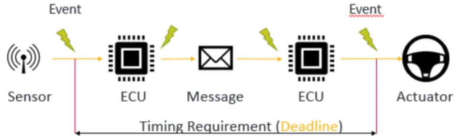
In the vehicular domain, timing requirements are translated as timing constraints on events or event chains [6]. For instance, Figure 5 illustrates an example of a distributed functionality timing requirement put between the event coming from the sensor detecting road obstacles and the event responsible for the actuating of the steering wheel.
Figure 5: A distributed vehicular functionality timing requirement example
An event could be defined as state change in a running system. It might occur at any distinct point on time which is also know as an occurrence of the event. There might be one ore more occurrence of the event. Events are used as a triggering method for a software function. Software functions might be time-triggered, too. Timing constraints are specified on the occurrences of a single event or a set of events. In the first case, the timing constraints are valid for any sub-sequence of the occurrences otherwise the constraints are valid for the occurrences of the set of events. Timing constraints are usually specified using two attributes representing lower and upper bounds. A constraint is said to be satisfied when the occurrences of the events happen within these limits. For more information about constraints and their interpretation, the reader can refer to [65]. In this framework, we group timing constraints in node and network constraints. We also note here that these constraints are in line with the AUTOSAR standard [66]. AUTOSAR is a software architecture standardization in the automotive domain whose main objective is to enable the implementation of the software functionalities independently from the hardware architecture [67].
Node constraints are:
• Delay Constraint - It constrains the time distance between the source triggering event and target response event, but the occurrence of target response event does not matter if it corresponds to the source triggering event or not. Hence, the period of activation for these two events can be different or equal.
• Strong Delay Constraint - It is similar to the previous constraint, but the occurrence of the target response event should match the occurrence of the source triggering event. In contrary to Delay Constraint this indicates the obligation of events for having an equal period. • Order Delay - It is a minor instance of the Strong Delay Constraint where the low attribute
limit is set to zero and the high one is set to infinite. What is more, the occurrence of the two events are not allowed to coincide.
• Repetition Constraint - It constrains the activation pattern of the occurrences of a single event where Jitter might also be present. Jitter indicates the maximum time that the activation of an event can be delayed.
• Repeat Constraint - It is a minor instance of the Repetition Constraint where an event is not allowed to experience any Jitter.
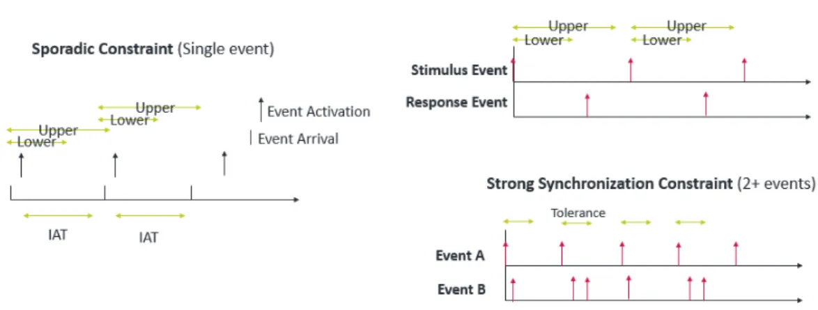
• Sporadic Constraint - It constrains the activation pattern of two consecutive occurrences of a single event to be sporadic. Additionally, the time distance between the two occurrences must be equal or higher than a minimum inter-arrival time. A maximum value of the inter-arrival time can also be specified.
• Periodic Constraint - It is a special instance of the Sporadic Constraint where the minimum and maximum inter-arrival times are equal. This is also referred as the period of the event. • Burst Constraint - It is also a special instance of the Sporadic Constraint where Jitter is not allowed. Also, in a particular time interval there is a fixed amount occurrences of the event and the time distance between two consecutive occurrences is higher than a minimum inter-arrival time.
• Pattern Constraint - It constrains the occurrences of the event to be activated following a specific pattern where fixed periodic points are pre-defined. Fixed periodic points are considered with respect to the starting reference point of the respective period also known as offset. Jitter might also be present.
• Arbitrary Constraint - It constrains the activation pattern of the occurrences of the event to be random and irregular.
• Execution Time Constraint - It constrains the execution time of a function where the pre-emptions or blocking during execution are not considered. For a function there are usually Best case execution time (BCET) and Worst case execution time (WCET) specified. • Synchronization Constraint - It constrains the way how occurrences of a group of events
follow each other. Every occurrence of every event in the event set should occur within a time limit margin known as window tolerance. Windows must have at least one occurrence from every event and they may overlap also.
• Strong Synchronization Constraint - It is similar to Synchronization Constraint but in a window there must exist at most one occurrence of every event. Moreover, overlapping windows is not allowed.
• Output Synchronization Constraint - It constrains the way how occurrences of events follow each other corresponding to a stimulus. Also applicable for event chains and distributed event chains .
• Input Synchronization Constraint - It constrains the way how occurrences of stimuli events follow each other corresponding to a response event. Similar to Output Synchronization Constraint it can be specified on chain of events or distributed chain of events also.
• Reaction Constraint - It constrains the time distance that a response event corresponding to a stimuli event must occur. It is applicable for event chains and distributed chains, but not applicable for individual events.
• Age Constraint - it is defined as ”“how long before each response the corresponding stimulus must have occurred”” [68] In other words, the maximum data age allowed from the input to the output of the chain. Similar to Reaction constraints it is applicable to event chains, distributed chains, but not individual events.
.
An illustration of Sporadic Constraint, Strong Delay Constraint and Strong Synchronization Constraint is shown in Figure 6.
Figure 6: An illustration of a subset of node constraints
Some of the node constraints valid for nodes are applicable to network and messages, too. This is because of the similarities, we have previously mentioned, between tasks and messages. In particular, the applicable constraints are those on the frequency and occurrence of a message and those put on the time distance between the occurrence of the message triggering event and the occurrence of event indicating finishing of the transmission. Hence, Network Constraints are:
• Repetition Constraint • Periodic Constraint • Sporadic Constraint • Pattern Constraint • Strong Delay Constraint
• Execution (Transmission) Time Constraint
We note here that in passive communication protocols some of the constraints might not be of interest. For instance, a CAN message might inherit the period from the task queuing it. Hence, verifying the periodicity constraint of the task will automatically ensure the periodicity of the message. However, messages can also be triggered by the network himself in case of active protocols e.g. HaRTES [69]. As a consequence, constraints on the frequency and occurrence of a message should be specified. Execution time constraint could be used for bounding the maximum transmission time of the message.
5.2
Timing Verification
After the system has been modeled, its timing information should be extracted and evidences on the system timing predictability provided. To this end, timing analysis are used to check whether or not the constraints described in Section 5.1.2 are satisfied. Researches have come up with pre-run time analysis techniques for different task models, scheduling policies or communication protocols. To this end, we group the timing verification as follows:
• Verification of timing constraints put on the frequency and occurrence of a single event or message such as Repetition, Repeat, Period constraints.
• Verification of synchronization timing constraints put on a group of events.
• Verification of timing constraints put on the time distance between the occurrence of the source triggering event and the occurrence of target response event. It can be either for tasks or messages.
• Verification of timing constraints put on event chains or distributed event chains (Distributed Systems).
We note here that pre-run time timing analysis techniques are used to verify constraints such as Delay, Age, or Reaction Constraints. An illustration of the phases towards timing verification of the constraints is shown in Figure 7.
6
Case Study
In order to validate the applicability and suitability of the proposed framework, we use it for cate-gorising and comparing two industrial modelling languages which are RCM [12] and Amalthea [13].
6.1
Rubus Component Model
Rubus Component Model (RCM) is a modelling language, core of the Rubus approach, which consists of several methods and tools for model-based software development of real-time embedded systems. It is developed by Arcticus Systems1 in co-operation with partners from academia and industry. RCM has been used in the vehicular domain for more than 25 years for the development of in-vehicle control functionalities [46]. Rubus-ICE is the RCM accompanying tool suite and consist of modeling and analysis tools, code generators as well as infrastructure for the run-time of application. Within Rubus-ICE, the applications are developed and described graphically as inter-connected components [46]. In RCM, a Software Circuit is the most basic component. SWCs are characterized by run-to-completion semantics meaning that, upon triggering, a SWC reads the input data, processes it according to the inner logic and provides an output. Figure 8 illustrates a multi-rate data chain in RCM which consists of 3 Software Circuits.
Figure 8: Multi-rate data chain modeling in RCM
6.2
Amalthea model and APP4MC
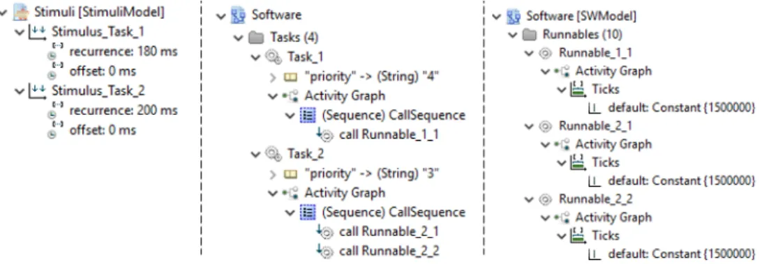
APP4MC is an open-source European project under Eclipse Public License whose objective is to provide a tool-chain for the engineering of real-time multi-core embedded systems [15]. It originates from the Amalthea and Amalthea4Public ITEA2 research projects [70]. It is still under develop-ment as it aims to cover all developdevelop-ment cycles of software starting from design to verification and validation of these systems [15]. To date, it provides the design and run-time infrastructure of real-time embedded systems applications. Systems are designed based on the Amalthea model [13] where the basic hierarchical element is called Runnable. A Runnable encapsulates the basic func-tions. They might be grouped in clusters and mapped to a task which is activated by Stimuli. Systems are designed as interconnected components, but yet not graphically supported. Figure 9 illustrates how this is concretely done in Amalthea.
Figure 9: Runnables and Tasks modeled with Amalthea
What is more, Amalthea is mainly focused on the automotive industry, but not strictly. How-ever, it is seen as an extension of the AUTOSAR [66] standard in different aspects and believed to
be a standard for multi-core real-time embedded systems in the vehicular domain [71].
6.3
Timing Model
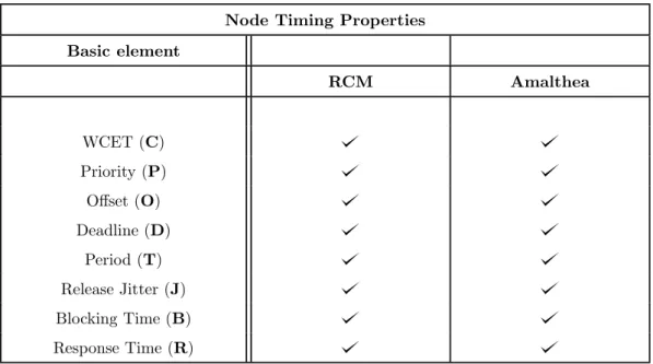
According to the proposed framework we study to what extent languages comply with it. First, we consider the basic node timing properties:
Node Timing Properties Basic element RCM Amalthea WCET (C) Priority (P) Offset (O) Deadline (D) Period (T) Release Jitter (J) Blocking Time (B) Response Time (R)
Table 1: Timing properties of element responsible for run-time behavior and communication. Since the very first steps of both modeling language development, the handling of the system’s timing properties and requirements has been one of the main focuses. As a consequence, the com-ponents responsible for the run-time behavior of the software facilitate many timing properties. Both languages express the timing properties identified in Table 1 and required by the pre-run time analysis such as Response-Time analysis. However, they do not support it at the same level of abstraction. For instance, timing properties are linked to a software component in RCM while in Amalthea to a Runnable which is a schedulable part of a software component [15]. What is more, a Runnable can be mapped to more than one task during run-time unlike RCM which is based on one-to-one mapping of SWCs to Tasks. In both cases, the respective components can be part of transactions (chains) of event-triggered or data-triggered nature. Single or multi-rate data-chains are also a feature of both. There is also a separation of signal flow and data flow between software components [9] [13]. What is more, timing properties identified in Table 1 are also valid for multi-core processor architectures. Both languages can enable modeling of multi-core applications theoretically. Practically, only Amalthea supports it as enabling RCM with multi-core support is still an under-going work [62].
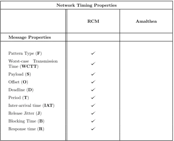
The second part of timing properties is related to the Network and protocols used for the communication between nodes.
Network Timing Properties
RCM Amalthea Message Properties Pattern Type (F) Worst-case Transmission Time (WCTT) Payload (S) Offset (O) Deadline (D) Period (T)
Inter-arrival time (IAT) Release Jitter (J) Blocking Time (B) Response time (R)
Table 2: Timing properties of the element responsible for data transmission between nodes. Inter-communication between nodes is one of the most essential parts when modeling distributed embedded systems. Components responsible for data transmission should express properties iden-tified in Table 2 to bound the delays and enable their timing analysis. The first obvious observation is that Amalthea does not facilitate any of the properties. It comes as a consequence of its scope that focuses on the optimization of applications developed for a single node with multi-core ar-chitecture [15]. Amalthea started as a project in 2011 for filling the gap of automotive standards lacking multi-core support. Hence, it is seen as a complement regarding multi-core to AUTOSAR, which itself supports the development of real-time distributed embedded systems [67]. On the contrary, RCM is capable of supporting the development of distributed embedded systems. It makes a distinction between intra and inter-node communication [9]. Inter-node communication is made through the use of messages and hence expressing the properties identified in Table 2. The identified properties are generally in a way that adding specific-protocol properties could easily make the modeling language to support that specific protocol. To this end, in RCM cur-rently, it is supported the modeling of CAN protocol and its higher protocols [9], modeling of TSN (IEEE 802.1Qbv-2015, IEEE 802.1Qbu2016) [64]. Flexray is not supported, but as we previously mentioned due to supporting of the general message properties, its implementation would not be difficult to be implemented [43].
6.4
Timing Constraints
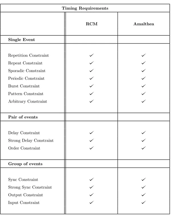
In this section we investigate how capable are the modeling language of translating the timing requirements in timing constraints on the developed software architecture.
Timing Requirements RCM Amalthea Single Event Repetition Constraint Repeat Constraint Sporadic Constraint Periodic Constraint Burst Constraint Pattern Constraint Arbitrary Constraint Pair of events Delay Constraint Strong Delay Constraint Order Constraint
Group of events
Sync Constraint Strong Sync Constraint Output Constraint Input Constraint
Table 3: Timing constraints put on a single event, pair of events and chain of events We borrowed the timing constraints from Timing Augmented Description Language that provided the AUTOSAR standard with a timing model. What is more, TADL2 is capable of modeling the timing information in various abstraction levels [6]. Amalthea obtains most of the timing constraints concepts for events, group of events and event chains exactly from TADL2. Hence, it is able to support timing constraints put on Table 3. Similarly, RCM is also capable of specifying these timing constraint. The work in paper [65] conducted a comprehensive refinement of all the TADL2 timing constraints (18 in total) aiming to support high precision timing analysis at higher
abstraction levels [46]. Both languages are also capable of constraining all the activation patterns of a single event occurrences. They permit the activation of events periodically, sporadically, or following a certain pattern [15] [65]. In the following table we identify the timing constraints put on a chain of events and distributed chain of events. Moreover, we also identify the timing constraints which could potentially be put on the network as well.
Timing Requirements
RCM Amalthea
Chain of events
Reaction Constraint Age Constraint Input Sync Constraint Output Sync Constraint
Distributed chain of events (Distributed Systems)
Reaction Constraint Age Constraint Input Sync Constraint Output Sync Constraint
Network
Repetition Constraint Periodic Constraint Sporadic Constraint Pattern Constraint Strong Delay Constraint Execution (Transmission) Time Constraint
Table 4: Timing constraints put on event chains and distributed event chains.
As we previously mentioned, RCM is capable of supporting all the timing constraints. As a consequence of having special components for doing this, it is capable of specifying these timing constraints on distributed event chains and on network. For instance, due to having a clear
separation of signal and data flow, a message could be easily stand-alone triggered periodically by attaching the special component responsible for periodic activation to its signal port. In contrary, we remind here that Amalthea does not support the distributed event chains, nor messages as a consequence also the timing constraints regarding them. However, regarding event chains within a node it is possible to specify all constraints identified in Table 4. However, the way how you can specify these timing constraints are different. For example, RCM has 2 special components for specifying delay and strong delay constraint while in Amalthea Strong Delay Constraint can be derived from Delay Contraint by configuring Mapping Type option to OneToOne [15] [65]. Besides timing constraints, Amalthea provides additional support for the mapping constraints of Runnables and Tasks to cores. Mainly for supporting multi/many core scheduling and timing analysis.
6.5
Timing Verification
The last part of the framework investigates the tool support for these modeling languages regarding the verification of the timing behavior. However, this is not done to a very detailed extent due to the thesis main focus on identifying the timing properties and constraints for enabling such tool support.
Timing Verification
Rubus-ICE APP4MC
The occurrence of a single event The occurrence of a message
Time distance between the occurrence of triggering event
and response event Synchronization Constraints put
on a group of events Constraints put on event chains
Constraints put on distributed event chains
Table 5: Timing verification on various events, event chains or group of events.
Rubus-ICE consists of a dedicated run-time analysis framework and also a real-time operating system Rubus RTOS. The timing analysis is developed as standalone plugins which are applied in the extracted timing model from RCM developed software architecture [46]. To this end, the repetition constraint on task could be easily verified if the tasks were being implemented at the user level of RTOS. Also, execution time constraints could be verified by construction as Rubus RTOS does not allow a particular task to run more or lower than the respective bounds. It is capable of ensuring all types of single event occurrence patterns. Input synchronization constraints are guaranteed by the offline scheduler which works on top of the fixed priority scheduling [65] while output synchronization constraints, delay, strong delay, age, and reaction could be verified by the end-to-end timing analysis. The end-to-end timing analysis is performed on the timing model extracted from software architecture modeled with RCM. The technique used for the extraction of the timing related information was developed keeping RCM in mind. However, it could be also applicable in other component modeling tools where pipe-and-filter is used as a technique for soft-ware components communication. Redundant timing information can be filtered and identify and
the information coming from the user, that from the modeled application, from the transactions, distributed transactions, mixed chains can be extracted in an unambiguous way [46].
On the contrary, APP4MC is an open-source development platform that aims to have open interfaces to create extensions for other tools regardless they are of the same nature or commer-cial [72]. Today, APP4MC covers only the design of real-time multi-core vehicular embedded sys-tems and provides the run-time framework for the mapping of software components and runnable to tasks, tasks to cores, and schedulers to cores. The verification of the timing model coming from these two processes has to be performed by third-party tools as APP4MC lacks a tool for the validation of timing requirements. However, commercial tools do not expose many details regard-ing the modelregard-ing techniques or timregard-ing analysis that they enable. In contrast, Rubus-ICE although being commercial the analysis techniques and methods has always been transparent to the research community [9] [46] [65] [73]. Some of the timing analysis tools supporting Amalthea models and APP4MC are Timing Architects [74], Symta/s [75], ChronSIM [76], MAST [77]. The first three tools do not expose much from their timing analysis techniques and methods. However, the latter exposes more information on what are its capabilities as of being an open-source academic tool. For instance, APP4MC support several scheduling algorithms including fixed-priority, dynamic-priority, or server based. MAST is capable of supporting different timing for analysis techniques uniprocessors, multiprocessors, and fixed priority or dynamic priority. Despite supporting them, MAST has also its designing tool whose timing analysis could be directly interpreted by the timing analysis tools. When Amalthea is the case, a model transformation should be made for MAST to interpret the timing information of the system. However, because of transformation some of the information might loose due to MAST not having corresponding components for covering all aspects of the software that Amalthea does. This was pointed out in [78]. Hence, timing analysis might be performed based on pessimistic assumptions. However, because most of the tools support the modeling transform, Amalthea has a greater range of timing analysis techniques that can be performed.
7
Conclusions
In this thesis work, we developed a comprehensive framework for capturing the timing properties that modeling languages should express to verify the timing predictability of vehicular real-time embedded systems. It is comprehensive mainly because of two reasons. First, it targets the distributed real-time vehicular embedded systems which are a composition of nodes and networks. Second, it identifies timing properties based on general models that are effortlessly extendable for specific vehicular timing analysis or communication protocols respectively. Additionally, timing constraints were borrowed from the timing model of an automotive standard and grouped on sub categories such as single events, chain of events, and messages. Being able to specify them would make the modeling languages compliant to the standards and easier to be transformed in a proper format for vehicular timing analysis engines. To this end, we elaborated the answer to the first RC being ”Which are the timing properties and related information for categorizing and comparing different modeling languages regarding the various types of timing analysis that they enable?”
However, timing models generated through the specification of timing-related information for different artifacts require interpretation to make use of them. The third part of the framework targets to what extent tools support the interpretation and verification of the timing model. Hence, to validate the applicability of the whole framework and the elaboration of the second Research Question being ”Can we use the framework for characterising and comparing two languages being Amalthea and RCM?” we took these modeling languages into consideration and their respective tool support. According to the observations and their framework compliance we came into several conclusions.
• Besides allowing for software architecture development of automotive software, both mod-eling languages allow for timing analysis during this process by expressing timing-related information such as timing properties and constraints for different artifacts. However, they have different scopes where Amalthea targets applications on single nodes with multi-core architectures while RCM focuses on distributed embedded systems with ongoing work for supporting single node multi-core architectures besides uniprocessor. Hence, a comparison could be made only if considering Single Node single-core architectures due to RCM not supporting Multi-core and APP4MC not supporting distributed systems. Both modeling languages are capable of triggering software components either event or data wise. They can also be part of transactions which can be multi-rate or single rate in case of data chains. Ad-ditionally, RCM supports generic message model which can easily be re-modeled according to some specific protocol properties.
• Modeling effort and learning curve for RCM and Rubus-ICE is minimal due to the designing approach for abstracting implementation details and explicit modeling of timing properties such as Jitter, Period of software circuits. Similarly, Amalthea model relies on sub-models for each aspect of software architecture increasing its understand-ability and usability. • APP4MC which is Amalthea’s tool support does not facilitate a timing analysis engine yet.
Hence, third party tools should be used for this matter. Amalthea is characterized by a high degree of timing expressiveness regarding single node applications of different architectures. To this end, having several tool-support enables a rich amount of timing analysis for dif-ferent scenarios. However, this comes with a drawback since timing model transformations appropriate for the third party tool should be made. In case, when it is not possible to fully translate the timing model due to lack of specific properties or components assump-tions are made. This might result in increasing the pessimism of timing analysis precision and results. However, commercial tools which supports Amalthea models such as Timing Architects [74] complement the development cycles that APP4MC lacks. Hence, precise timing analysis especially for multi-core applications can be performed. On the other hand, Rubus-ICE is upgraded continuously through several projects in collaboration with academia and end-users. New components are added to adopt state-of-the-art research timing analysis proposed by academia and meet the needs of end-users. The extendability of the tool-suite was kept in mind since the first steps of its development. First covering only single Node uniprocessor architectures and now resource constrainted real-time embedded systems with several network communications and on-going work for multi-core node architectures.
8
Future Work
The main direction for future research includes extending of the framework by identifying the timing properties based on state-of-the-art timing analysis techniques for many-core and heterogeneous processor architectures. Also, modeling languages and their tool support might expresses different timing properties, might implement complex analysis techniques, might be upgraded to cover more aspects of a system, but this should be abstracted as much as possible to minimize the learning curve for the practitioners and engineers. Hence, adding additional information in the framework for this matter could be added to help one see the trade-off between the understand-ability, ease of use, and the capability of the languages for enabling timing analysis.
Another interesting research direction could be the investigation of real-time embedded systems modeling languages regardless of their scope. For instance, the scope of this thesis was narrowed towards the modeling languages used in the vehicular domain. However, real-time embedded systems applications in different domains such as aerospace, medical, the chemical industry might share common timing properties and requirements. Hence, a refinement of the framework and a more comprehensive classification could be established.
9
Acknowledgments
This thesis work has been one of the most challenging journeys that I have had so far. A journey whose end I could not have reached without the continuous support and guidance of my two supervisors Alessio Bucaioni and Mohammad Ashjaei. I would like to express my deepest gratitude to them for believing in me and for the positive vibes during the weekly meetings. I would also like to thank my examiner Saad Mubeen for his revisions and detailed technical feedback. Last but not the least, ....
References
[1] P. Liggesmeyer and M. Trapp, “Trends in embedded software engineering,” IEEE Software, vol. 26, no. 3, pp. 19–25, May 2009.
[2] C. Ebert and J. Favaro, “Automotive software,” IEEE Software, vol. 34, no. 3, pp. 33–39, May 2017.
[3] S. S. Amberkar, B. J. Czerny, J. G. D’Ambrosio, J. D. Demerly, and B. T. Murray, “A compre-hensive hazard analysis technique for safety-critical automotive systems,” SAE transactions, vol. 110, pp. 282–292, 2001.
[4] P. Liggesmeyer and M. Trapp, “Trends in embedded software engineering,” IEEE Software, vol. 26, pp. 19–25, May 2009.
[5] B. Sch¨atz, A. Pretschner, F. Huber, and J. Philipps, “Model-based development of embedded systems,” in International Conference on Object-Oriented Information Systems. Springer, 2002, pp. 298–311.
[6] TIMMO Methodology , Version 2. TIMMO (TIMing MOdel), Deliverable 7, October 2009. The TIMMO Consortium.
[7] S. Mubeen, E. Lisova, and A. V. Feljan, “Timing predictability and security in safety-critical industrial cyber-physical systems: A position paper,” Applied Sciences–Special Issue ”Emerg-ing Paradigms and Architectures for Industry 4.0 Applications”, vol. 10, no. 3125, pp. 1–17, April 2020.
[8] N. Feiertag, K. Richter, J. Nordlander, and J. Jonsson, “A Compositional Framework for End-to-End Path Delay Calculation of Automotive Systems under Different Path Semantics,” in International Workshop on Compositional Theory and Technology for Real-Time Embedded Systems, CRTS 2008, December 2008.
[9] S. Mubeen, J. M¨aki-Turja, and M. Sj¨odin, “Support for end-to-end response-time and delay analysis in the industrial tool suite: Issues, experiences and a case study,” Computer Science and Information Systems, vol. 10, no. 1, 2013.
[10] M. Becker, D. Dasari, S. Mubeen, M. Behnam, and T. Nolte, “End-to-end timing analysis of cause-effect chains in automotive embedded systems,” Journal of Systems Architecture, vol. 80, pp. 104 – 113, 2017.
[11] L. Lo Bello, R. Mariani, S. Mubeen, and S. Saponara, “Recent advances and trends in on-board embedded and networked automotive systems,” IEEE Transactions on Industrial Informatics, vol. 15, no. 2, 2019.
[12] K. Hanninen, J. Maki-Turja, M. Nolin, M. Lindberg, J. Lundback, and K. Lundback, “The rubus component model for resource constrained real-time systems,” in 2008 International Symposium on Industrial Embedded Systems, June 2008, pp. 177–183.
[13] Amalthea: Deliverable: D 3.4 Development of Scheduling Analysis and Partitioning/Mapping Support Tools. Work package 3. April 2014.
[14] S. Mubeen, H. B. Lawson, J. Lundb¨ack, M. G˚alnander, and K. Lundb¨ack, “Provisioning of predictable embedded software in the vehicle industry: The rubus approach,” in 2017 IEEE/ACM 4th International Workshop on Software Engineering Research and Industrial Practice (SER IP), May 2017, pp. 3–9.
[15] APP4MC project. APP4MC Help Documentation (June 2020). [Online]. Available: https: //www.eclipse.org/app4mc/help/app4mc-0.9.8/index.html, Accessed: 2020-06-09.
[16] Q. Li and C. Yao, Real-Time Concepts for Embedded Systems, 1st ed. USA: CRC Press, Inc., January 2003, Chapter 1 pp. 3-4.