Screen Printed Large Area Sensors for
Pressure Distribution Monitoring in
Wheelchairs
Jawad Ahmad
Main supervisor: Associate Professor Johan Sidén Co-supervisor: Dr. Henrik Andersson
Department of Electronics Design
Thesis for Licentiate Degree in Electronics Design Mid Sweden University
Holmgatan 10 851 70 Sundsvall
Akademisk avhandling som med tillstånd av Mittuniversitetet i
Sundsvall fram-läggs till offentlig granskning för avläggande av
licentiatexamen torsdag, den 04 Juni 2019, kl. 09:30, sal M108, Mittuniversitetet Sundsvall. Seminariet kommer att hållas på engelska.
Screen Printed Large Area Sensors for Pressure Distribution
Monitoring in Wheelchairs
© Jawad Ahmad
Printed by Mid Sweden University, Sundsvall, Sweden, 2019 ISSN: 1652-8948
ISBN: 978-91-88947-05-5
Department of Electronics Design
Faculty of Science, Technology and Media
Mid Sweden University, Holmgatan 10, SE-851 70, Sundsvall, Sweden Phone: +46 (0)10 142 80 00
Abstract
A sedentary lifestyle can induce health related problems including pres-sure ulcers. Prolonged sitting inadequacies constitute a risk for prespres-sure ulcer to many individuals, in particular people with disabilities and re-duced mobility. The measurement of distributed pressure and detection of irregular sitting postures are essential in prevention of the risk of devel-oping pressure ulcers.
In this thesis, a screen-printed pressure sensor for a large area is pre-sented, with the objective of measuring the distributed pressure of a seated person in a wheelchair. The conductors and interdigital patterns are printed with silver-based ink. A blend of a non-conductive and a low resistive ink is used for customized resistance for an optimal sensing range of the pressure sensor. The effect of moisture and temperature are realized in an environment chamber. For characterization, other key performance tests such as repeatability, drift and flexibility are carried out. The surface morphology is carried out for structural analysis of printed samples. The sensor data is acquired and processed using an 8-bit ATmega-2560 micro-controller and wirelessly transmitted to a PC for post-processing, storage and analysis. For real-time data presentation of distributed pressure points, a GUI has been developed to display the values obtained from the large area sensor. The detection of four sitting postures; forward leaning, backward leaning, left leaning and right leaning along with a normal sit-ting posture is attained. An analysis for stretchable printed tracks has been conducted to investigate the changes in electrical resistance using elonga-tion tests, surface morphology and EDS. The optimal curing time and tem-perature were investigated to manufacture stretchable conductive tracks. In summary, the contributions in this thesis provides an effective ap-proach regarding pressure distribution measurement and recognizing ir-regular sitting postures for wheelchair users.
Sammanfattning
En stillasittande livsstil kan framkalla hälsorelaterade problem, inklusive trycksår. Långvariga sittande brister utgör en risk för trycksår för många individer, särskilt personer med funktionsnedsättning och nedsatt rörlighet. Mätningen av distribuerat tryck och detektering av oregelbundna sittställningar är avgörande för att förebygga risken för att utveckla trycksår.
I denna avhandling presenteras en screentryckt tryckgivare för stora areor för att mäta det tryckfördelningen hos en person i en rullstol. Ledarna och interdigitala mönstren är tryckta med silverbaserat bläck. En blandning av ett ickeledande och ett lågresistivt bläck används för anpassad resistans för optimalt avkänningsområde för tryckgivaren. Effekten av fukt och temperatur uppnås i en miljökammare. För karakterisering utförs andra prestandatester såsom reproducerbarhet, drift och flexibilitet. Ytmorfologi utförs för strukturell analys av tryckta prover. Sensordata inhämtas och bearbetas med en 8-bitars ATmega-2560 mikrokontroller och överförs trådlöst till en dator för processning, lagring och analys. För datapresentation av distribuerade tryckpunkter i realtid har ett GUI utvecklats för att detektera sittställningen för en person utifrån mätning av de distribuerade tryckpunkterna. Detektering av fyra sittställningar; framåtlutande, bakåtlutande, vänsterlutande och högerlutande tillsammans med normal sittställning är uppnått. En analys för sträckbara tryckta ledare har gjorts för att undersöka förändringar i elektrisk resistans med hjälp av töjningstester, ytmorfologi och EDS. Den optimala härdningstiden och temperature undersöktes för framställning av töjbara ledande spår.
Sammanfattningsvis ger bidragen i denna avhandling ett effektivt tillvägagångssätt när det gäller mätning av tryckfördelning och erkännande av oregelbundna sittställningar för rullstolsburna.
Acknowledgements
First and foremost, I am thankful to Almighty Allah, the most merciful and the most beneficent for the countless blessings. Secondly, I am very grateful to my supervisor Assoc. Prof Johan Sidén for his kind advices, guidance and personal interest throughout this thesis work. His encour-agement and support provided me with an opportunity to work freely on my thesis.
Thanks to my co-supervisor Dr. Henrik Andersson for his support, con-structive comments that helped me in starting and continuously improv-ing this work. Thanks to Dr. David Krapohl for his internal review. Special thanks to my family for their endless love, countless prayers and extraor-dinary support.
I am especially thankful to Xiaotian Li, Farhan Alam, Muhammad Abu Bakar, Seyed Morteza Ebadi, Muhammad Nazar ul Islam, Qaiser Anwar, An Siwen, Cristian Vilar, Irida Shallari, Hiba Alqaysi and Waqas Ahmad for extremely valuable support and encouragement. I would acknowledge all colleagues whose names are not mentioned here for their support and kindness, during my entire study programme. I am thankful to all non-academic friends who supported and encouraged me.
Contents
Abstract ... ii
Sammanfattning ... iv
Acknowledgements ... vi
Terminologies ... xii
List of Figures ... xiv
List of Tables ... xvi
List of Papers ... xviii
1 Introduction ... 1 1.1 General overview ...1 1.2 Problem motivation ...1 1.3 Research goals ...4 1.4 Contributions ...5 1.5 Thesis outline ...7
2 Background information and functional materials ... 9
2.1 Printed electronics ...9
2.2 Printing technologies for printed electronics ...9
2.2.1 Screen-printing and fabrication of conductive interconnects ...9
2.2.2 Inkjet printing of conductive interconnects ... 10
2.2.3 Transfer printing for printed electronics... 11
2.2.4 Non-conventional electronics with methods other than printing .. 12
2.3 Functional materials ... 12
ix
2.3.2 Nanoparticle inks based on Ag ... 12
2.3.3 Nanoparticle inks based on Carbon ... 13
2.3.4 Nanoparticle inks based on Au ... 13
2.3.5 Ink based on conductive polymers ... 14
2.4 Substrates ... 14
2.4.1 Polyethylene terephthalate (PET) ... 14
2.4.2 Thermoplastic polyurethane (TPU) ... 14
2.4.3 Polydimethylsiloxane (PDMS) ... 15
2.4.4 Related work ... 15
3 Large area pressure sensor ... 17
3.1 Design of a large area pressure sensing system ... 17
3.1.1 Design of large area pressure sensor matrix ... 17
3.1.2 Fabrication of printed sensors and interconnects ... 19
3.1.3 Design of read-out electronics ... 19
3.1.4 Sitting posture recognition ... 21
4 Results ... 23
4.1 Characterization ... 23
4.1.1 Drift ... 24
4.1.2 Environmental chamber testing ... 24
4.1.3 Bending testing ... 25
4.1.4 Stretchable conductive tracks ... 26
5 Discussions ... 29
5.1 Validity of results ... 29
5.2 Limitations and possible improvements of proposed large area pressure sensor ... 29
5.3 Ethics and impact on society ... 30
5.3.1 Ethics ... 30 5.3.2 General considerations ... 30 5.3.3 Impact on society ... 30 6 Summary ... 31 6.1 Conclusion... 31 6.2 Future work ... 32 Bibliography... 33 Appendix I ... 39
Terminologies
Abbreviations and Acronyms
Ag --- Silver
ASTM --- American society for testing and materials Au --- Gold
C --- Carbon
CNP --- Carbon nanopa rticles CNT --- Carbon nanotubes Cr --- Chromium
kPa --- kilo Pascal
KOH --- Potassium hydroxide LCD --- Liquid crystal display NP --- Nanoparticle
OLED --- Organic light emitting diode PEDOT --- Poly (3, 4-ethylenedioxythiophene) PDMS --- Polydimethylsiloxane
PI --- Polyimide PU --- Polyurethane
RFID --- Radio frequency identification TPU --- Thermoplastic polyurethane
List of Figures
Figure 1.1: Research work flow………5
Figure 1.2: Map of contributions to goals of research studies……….…7
Figure 2.1: Graphical representation of transfer printing process…….11
Figure 2.2: Stretchable electrodes using PDMS………...….15
Figure 3.1:Figure 3.1: Block diagram of large area pressure monitoring system………...…….…....17
Figure 3.2: Placement of sensing elements in large area Pressure sensor………...……….…...18
Figure 3.3: PCB design of read-out electronics (Front-side and Backside) ……….………... 20
Figure 3.4: Response time for normal actuation of a sensing element……….………….…....20
Figure 3.5: Screenshots of pressure intensities acquired at about 35° leaning angle. (a) Forward leaning (b) Backward leaning (c) Right leaning (d) Left leaning……….…….21
Figure 4.1: Resistance graph as a function of force ….………...23
Figure 4.2: Temperature and humidity effects………25
Figure 4.3: Elongation setup for stretchable interconnects……….26
Figure 4.4: Morphology of printed samples. (a) Nanometre sized carbon particles (b) Micrometre sized Ag flake (c) Cross section of printed carbon (d) Cross section of printed Ag flake.……….…....27
Figure 4.5: (a) SEM micrograph (SE) of a sample cured at 150 °C for 30 minutes (b) SEM micrograph (in-beam SE) of a sample cured at 110 °C for 3 minutes (c) SEM micrograph of a sample cured at 110 °C for 10 minutes, having damaged conductivity (overstretched)………...…28
List of Tables
Table 1.1: Authors’ Contributions………6
Table 4.1: Sensor Drift (%) ……….24
Table 4.2: Bending Test………...…25
List of Papers
This thesis is mainly based on the following papers, herein referred to by their roman numerals:
Paper I ………... 41 Sitting Posture Recognition using Screen Printed Large Area Pressure Sensors
Jawad Ahmad, Henrik Andersson and Johan Sidén In Proceedings of IEEE Sensors. (IEEE Sensors). pp. 232-234.
Paper II ………. 47 Screen-Printed Piezoresistive Sensors for Monitoring Pressure Distribution in Wheelchair
Jawad Ahmad, Henrik Andersson and Johan Sidén IEEE Sensors Journal, vol. 19: 6, pp. 2055-2063.
Paper III ……….………….….……. 59 An Analysis of Screen-Printed Stretchable Conductive Tracks on Thermoplastic Polyurethane
Jawad Ahmad, Xiaotian Li, Johan Sidén and Henrik Andersson Accepted in IEEE FLEPS, July 7-10, 2019.
1 Introduction
1.1 General overview
The current consumer electronics market is shifting towards thin, com-pact and flexible electronics. In general, a considerable number of re-search studies are being carried out to find alternatives to copper con-ductor [1]. A variety of cheap, thin and flexible sensing devices are being made that can be used as an advancement or alternative to existing de-vices. Nonconventional electronics have the potential to be utilized as sensing devices that can be bent, folded and even stretched. For health monitoring, user-interactive materials with unique sensing capabilities are being used to detect vital signs of the human body [2].
This thesis aims at design and implementation of large area pressure sensors for measurement of distributed pressure of wheelchair-bound in-dividuals. The unobtrusive pressure measurement method a uses large area printed pressure sensor that is placed inside a wheelchair cushion. It is flexible and suitable for long-term operation. The sensing measure-ments are not noticeable and may not pose any discomfort to the wheel-chair users. The large area sensing system assists the health monitoring of disabled patients. A runtime pressure distribution mapping has been developed that demonstrates intensity of pressure over distributed pres-sure. The developed system is capable of recognizing four sitting pos-tures; forward-leaning, backward-leaning, right-leaning and left-leaning with an overall recognition accuracy of over 80 %.
1.2 Problem motivation
Pressure ulcers can affect the quality of life of wheelchair users [5], [7]. The data about the pressure distribution of a wheelchair user is very im-portant in order to prevent pressure sores from developing in the first place [6]. Some environmental factors such as humidity, temperature and cleanliness influences the skin and underlying tissues. The effect of pres-sure is proportional to the weight of the person, and can affect the skin if the wheelchair user is constantly sitting in a specific position [50]. The vessels get less blood and less oxygen, which adversely affects the skin tissues.
2
The problem is severe in those individuals who have lost sensation in a body part due to spinal cord injuries, partial paralysis or any other phys-ical impairment [8]. This group of people cannot get a feeling of move-ment due to a lack of sensation and are therefore unable to change their sitting or lying position. This category of patients possesses a higher risk of developing pressure sores.
The National Pressure Ulcer Advisory Panel (NPUAP) has catego-rized the pressure ulcer in four stages [9].
1) In stage one, the skin is intact and pressurized areas develop light or dark pigmentation.
2) In stage two, partial loss of skin occurs and an exposed wound be-comes visible in the form of a raptured blister.
3) In stage three, the skin becomes deeply damaged and the wounds reach the inner layers of skin.
4) In stage four, the skin flap disappears while muscles and bones under the skin become visible.
A constant pressure over a period of time causes impediment in blood flow, limiting oxygen supply to skin tissues and leads to localized and deep tissue pressure injury (DTPI) [10]. The tolerance of pressure varies for individuals; however, it is suggested that a pressure exceeding 32 mm Hg may cause occlusion in blood vessels [4]. In wheelchair users, a pres-sure ulcer most commonly appears around ischial tuberosities, calcaneus and the back of the knee [11], but can also occur in other areas of skin due to lack of mobility, moisture, friction and shear. Most pressure ulcer pa-tients suffer not only from pain, but also require a costly treatment. It is then suggested that early stage diagnosis of pressure sores helps in their treatment and recovery, otherwise late diagnosis results in a complicated process of treatment. Pressure ulcer treatment is extremely difficult, ex-pensive [12], [13], takes a lot of time and patience, and sometimes requires plastic surgery and a skin flap [14]. It is therefore suggested to monitor the pressure distribution for the wheelchair user for a specific time so as to develop prevention and rehab plans [15], [16]. In order to obtain an overview of a patient’s preliminary sitting habits and to get the pressure distribution data, pressure sensors are required to measure the amount of pressure over a certain area. For this purpose, a light and thin large area pressure sensor is proposed that can measure the pressure over
distrib-uted points of the whole sitting area, recognize movements and deter-mine centre of balance. The data can be processed to show a real-time pressure distribution intensity in the form of a pressure map along with sitting posture recognition. The data is stored as a log to be analysed by a medical doctor or therapist for the development of prevention measures or recovery strategies.
Manufacturing of such measurement sensors and devices would be possible on larger areas by using cost effective printing processes such as screen-printing, gravure printing, flexographic printing and inkjet print-ing [3]. Printed electronics possesses the advantage of fast and large vol-ume manufacturing. Moreover, the materials such as plastic and paper being used in the printed electronics industry are cost-competitive. The screen-printing method is being used for high throughput large area printed electronics. A screen print resolution of 100 µm and higher can easily be achieved using commercially available conductive inks on com-mon screen-printing setup [4]. Pressure is force over unit area and math-ematically it is described as:
𝑃 =𝐹
𝐴 (1) For the human body, the pressure is related to body weight over skin contact surface area. The human skin contains three layers: epidermis, dermis and subcutis. All three layers are composed of different skin tis-sues and muscles. The measurement of pressure at a specific point is re-lated to body weight and the stiffness and composition of skin tissues. A constant pressure over a longer period of time causes restriction in blood flow in the skin capillaries (ischemia) that can induce a pressure ulcer. Subcutis tissues and muscles are more susceptible to pressure sores and the risk of an internal wound is higher than what appears on the skin. Pressure measurement and sitting posture recognition is very important for wheelchair-bound patients to encounter pressure ulcer. A reposition-ing is required every 2 hours [51], and the caregiver treats this manually. A smart powered wheelchair has the capability of moving the seat to a particular extent while maintaining the balance. A powered wheelchair equipped with large area pressure sensor can analyse the continuous po-sition of a seated person for a specific time period, and can then lean au-tomatically to a different position using an electromechanical setup.
4
1.3 Research goals
The findings can have a strong implication for the development of cost-effective pressure sensors, especially within medical and health care ap-plications and sitting posture monitoring.
The clear objectives and verifiable goals are:
• Utilization of a cost-effective manufacturing technique and non-conventional thin and flexible electronics for pressure sensor fab-rication.
• Distributed pressure determination/measurement and sitting posture recognition using wirelessly received data, processing and logging.
• Characterization of the fabricated sensors in normal and harsh situations (environmental testing) to inspect the functionalities and robustness.
• Development of stretchable interconnects that will lead to fabri-cation of printed stretchable pressure sensors.
A combination of theoretical and experimental research has been used to identify appropriate design parameters, to support available ex-perimental methods, and to fabricate and characterize large area pressure sensor. The methodology is primarily based on three key research ques-tions which are stated as follows:
RQ 1: Investigation of a feasible, suitable and cost-effective method to fabricate thin and flexible pressure sensors that can be used for larger areas such as wheelchair cushions.
RQ 2: What would be the efficiency, robustness and practical im-plementation scenarios of a fabricated large area pressure sensor? RQ 3: Investigation on new materialsto further enhance the ca-pabilities of pressure sensors to incorporate features such as stretchability.
Literature Review Research problem
identification
Research approach definition
State of the art investigation Research question formulation Proposed sensor design Characterization Result / analysis Feedback
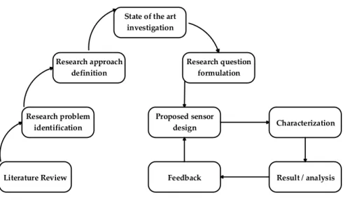
Figure 1.1: Research work flow
A review has been conducted for research objective verification on the basis of the research questions formulated and with a view to future work directions.
1.4 Contributions
The work in this thesis is summarized in the following papers, which are included at the end of this work:
• Paper I aim to answer RQ1 by introducing the core idea of em-ploying a large area pressure sensor for use in a wheelchair. Sen-sor design and read-out electronics design are presented. A sitting posture recognition algorithm determines four sitting positions. The posture recognition algorithm is tested on five able-bodied volunteers and has an accuracy of over 80 %.
• Paper II is an extension of Paper I, and aims at design improve-ments and a detailed approach in which a characterization is car-ried out for the printed sensors to determine the performance un-der different environmental conditions. An improved and com-pact read-out electronics is also developed for fully wireless inte-gration. This work aims to address RQ2.
• Paper III proposes a gateway towards the fabrication of multi-layered stretchable pressure sensors. The first step is to determine
6
the performance of stretchable substrates and stretchable inks un-der elongation in orun-der to obtain characterization of the conduc-tion parameters of stretchable printed interconnects. The pro-posed work aims to address RQ3.
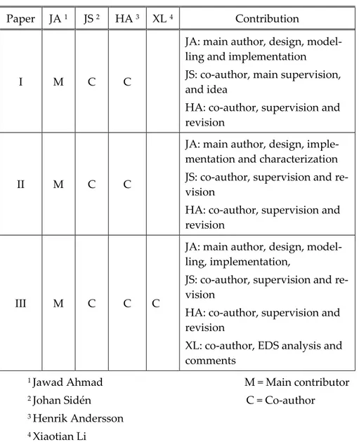
Table 1.1 Authors’ Contributions
Paper JA 1 JS 2 HA 3 XL 4 Contribution
I M C C
JA: main author, design, model-ling and implementation JS: co-author, main supervision, and idea
HA: co-author, supervision and revision
II M C C
JA: main author, design, imple-mentation and characterization JS: co-author, supervision and re-vision
HA: co-author, supervision and revision
III M C C C
JA: main author, design, model-ling, implementation,
JS: co-author, supervision and re-vision
HA: co-author, supervision and revision
XL: co-author, EDS analysis and comments
1 Jawad Ahmad M = Main contributor 2 Johan Sidén C = Co-author 3 Henrik Andersson
1.5 Thesis outline
The flowchart in Fig 1.2 describes the general goal, sub-goals and contri-butions.
Printed sensors for pressure ulcer prevention Flexible pressure sensors Sitting posture recognition and characterization Stretchable interconnects
Paper I Paper II Paper III
Contribution:
Design and fabrication of large area pressure sensors
Contribution:
Characterization of large area pressure
sensors Contribution: Stretchable interconnects and characterization RQ1 RQ2 RQ3
8
The thesis is divided into six chapters and is organized as follows:
1. Introduction The chapter features the thesis
over-view, problem motivation, objectives and research goals.
2. Background information
and functional materials
This chapter contains background reading about printing techniques and related work. It also includes state of the art for conductive inks, flexible and stretchable substrates
3. Large area pressure sen-sor
This chapter describes the design and fabrication of a large area pressure sensing system.
4. Results This chapter describes general and
characterization results
5. Discussions This chapter contains discussions
about limitations, improvements and ethical aspects
6. Summary The final chapter presents the
pri-mary conclusion of the thesis and suggestions for future work.
2 Background information
and functional materials
2.1 Printed electronics
Printed electronics relate to the process of manufacturing electronics products that employ graphical printing techniques. This type of electron-ics is sometimes called non-conventional electronelectron-ics. The wide range of functional materials and substrates enables the products to feature ad-vantages and functionalities that are unrivalled by other manufacturing methods. Printed electronics are usually manufactured at low cost and comprise high-speed processes such as screen-printing, roll-to-roll pro-cess, gravure, flexography etc.
Printed electronics requires an in-depth knowledge of material sci-ence, as there are a considerable number of technological advancements being made towards exciting new materials that can benefit this technol-ogy. Many electronic devices rely on printing technology, which are dif-ficult to manufacture with other processes. Some of devices include flexi-ble screens, smart posters, intelligent labels etc. It is estimated that by year 2025, the global revenue of the printed electronics industry will reach over 19 billion US dollars [17]. There is a huge existing market for printed elec-tronics for glucose sensors, OLED displays, RFID antennas and printed sensors.
2.2 Printing technologies for printed electronics
Printing techniques for flexible and stretchable electronics depend on the nature of the ink and substrate, but also relate to the viscosity of the ink, curing technique, temperature tolerance of the substrate and resolution of printed pattern. Screen-printing and inkjet printing techniques are dis-cussed in the next section.
2.2.1 Screen-printing and fabrication of conductive interconnects
Screen-printing is one of the fast and cost competitive printing techniques for fabrication of flexible and bendable devices and interconnects. Screen printing is widely used for large area printing in industrial processes. Screen printing is mainly a batch process, but advanced rotary machines exist too. In screen-printing, high viscosity conductive ink is applied to a10
substrate by forcing it through a fine mesh of synthetic thread with the help of a squeegee. Silk or any other synthetic fabrics can also be used for making a mesh that is firmly attached to a metal or wooden frame. The patterns are made by a photographic technique with stencils while allow-ing inks to flow through certain parts and blockallow-ing other parts. Mesh size is calculated in threads per inch or threads per centimetre. More threads result in a better print resolution, but also depends on the viscosity of the ink.
The current printed electronics technology mostly relies on carbon and silver conductive inks, which are made by mixing flakes or nanopar-ticles in temperature or ultraviolet curable /dryable solvents and adhe-sives. Screen-printing is therefore used to print thicker inks of relatively high viscosity. Thick layers (> 10 µm) are possible via this method, but the print resolution is limited to about 100 µm. This method is effective in printing multiple thick layers to achieve a certain thickness and required conductance. RFID antennas, car window heaters, membrane keyboards, are common examples of the devices that uses screen-printed techniques. Multiple wet-on-wet coatings are applied using screen-printing [18] and variable print thickness and sheet resistances are attained. Similarly, mul-tiple dry coatings are possible with screen printing. 6 coatings of a Ag ink EDAG 725-A is reported in [19], achieving a 7.3 mΩ/sq/42 µm sheet re-sistance value, while first printing 3 wet-on-wet coatings and curing them and again printing 3 wet-on-wet coatings aligned to previously cured coatings.
2.2.2 Inkjet printing of conductive interconnects
Inkjet printing is considered the most promising technique to print out very fine patterns on different substrates. This modern printing method uses electronics to control the movement of the nozzles and the number of droplets of ink. The high-end inkjet printer can “jet” a 5-micron droplet size and the common notation for drop size is pico-litres. Inkjet printing is a non-contact printing process that deposits printable composites onto a variety of substrates in a drop-by-drop method. With the current ad-vancements, it is now feasible to print prototypes and even large-scale industrial production at a relatively cheap cost. Thicker multi layered pat-terns can be deposited by multiple print sequences to allow higher con-ductance but the robustness of bonding depends on the first layer and
substrate surface. The droplets can be generated by different mechanisms; A continuous inkjet mechanism uses an electrical field to direct the drop-lets and the remainder are collected and recycled, this is the first ap-proach. The second mechanism uses the droplet on demand principle with subcategories thermal inkjet, electrostatic inkjet and piezo inkjet. For printing electronics circuits and interconnects, nanoparticle-based inks are commonly used, but any less viscous ink can be filled in the print car-tridges.
A brief review is reported in [20], which covers the technology as well as the use of this method along with functional materials in fabrica-tion of flexible/stretchable electronics. Multilayer inkjet-printed passive components for printed electronics is reported in [21], using Ag nanopar-ticle ink and utilizing piezoelectric print heads in Fujifilm’s Dimatix (DMP) 3000.
2.2.3 Transfer printing for printed electronics
Transfer printing is an emerging technique for fabricating electronic de-vices within different material classes and functional layouts. This print-ing method is most useful in the fabrication of flexible and stretchable electronics. In this printing method, the circuit or conductive interconnect is first printed onto a flexible substrate (non-textile) that is called a stamp (donor) and later transferred to other substrates (receivers) such as tex-tiles via a separate method. The process includes bringing up the stamp in contact with first substrate (donor), which is printed with inks and re-moved via chemical etching or dry lifting off. This stamp is brought into contact with the desired substrate (receiver) with appropriate adhesives and finally, the removal of the stamp completes the printing process. The transfer printing process is shown graphically in Fig. 2.1. This is quite a promising technique for complex flexible and stretchable electronics but
12
this printing process has a lower yield. Common transfer techniques in-clude dye sublimation transfer, heat/melt transfer, film release and wet transfer. Various transform techniques are listed in [22] on different sub-strates and varying stamps.
2.2.4 Non-conventional electronics with methods other than printing
A variety of methods has been reported to manufacture stretchable elec-tronics. For example, the construction of a stretchable tri-axis force sensor using conductive liquid is reported in [23], which uses electroconductive liquid encapsulated channels/tubes inside an elastomer. The overall thickness of the constructed device has been reported as 2.1 mm. Similarly, metallic interconnects are embedded inside an elastomer such as PDMS, where the metallic wire is kept in the shape of a horseshoe, sawtooth, zigzag or square wave patterns for easy stretching without breakage of the metallic wire. CNT electrodes are patterned on PU substrate in [24] and lithographic technique combined with KOH etching was used.2.3 Functional materials
2.3.1 Conductive printable inks
Many commercial inks are based on conductive fillers such as silver and carbon. Expensive inks that contains Au nanoparticles are available for research purposes. Graphene and carbon nanoparticle-based inks are be-ing investigated to achieve higher conductance. Common categories of commercially available inks include: Ag flake-based inks, carbon nano-tubes (CNT) filler-based inks, Ag particle-based inks, Ag nanowires-based inks, graphene-nanowires-based inks and other conductive polymers and composites. Most inks are soluble and washable with organic solvents such as Methyl Ethyl Ketone (MEK).
2.3.2 Nanoparticle inks based on Ag
Ag nanoparticle-based inks are mostly studied as they are inherently highly conductive yet only moderately expensive. Ag is a metal with su-perior conductivity at room temperature and is resistant to oxidation and corrosion. Instead of using bulk metal, a powdered form can be used in making an ink, which is a multicomponent formula that contains adhe-sive binders and metal (micrometre/nanometre scaled flakes or particles). This gives more flexibility of usage/printing on a range of substrates at
the cost of an increased resistance of mΩ scale. Flexible Ag inks are most commonly used in the electronics industry as the alternative to rigid wires, while more modern stretchable Ag inks are also commercially available [25]. Adding Ag nanoparticles to currently available flake based inks can further improve the conductivity [26], [27]. Most of the available screen printable commercial inks have a sheet resistivity of 10 - 15 mΩ/sq/25 µm and offer temperature curability at 120 °C. Inkjet printing of silver inks has less abrasion resistance (ASTM 3), but their overall sheet resistance when the sample is cured at 130 °C remain in the range of ≤ 5 mΩ/sq/25 µm [28]. Ag nanoparticle-based inks have been reported to have even lower resistances 30 µΩ/cm, while Ag nano-platelets have 7.4 µΩ/cm using novel sintering methods [29].
2.3.3 Nanoparticle inks based on Carbon
Carbon inks are inexpensive and are used as printed resistors, electrical attachments, heaters, membrane switches, polymer thick film circuitry and sometimes as a protective layer of another circuitry. Pure carbon is a non-metal with inferior conductive properties at room temperature and resistant to oxidation and corrosion. Different states and isotopes of car-bon (carcar-bon black, graphite, graphene and nanowires) are used to manu-facture carbon ink. Newer conductive carbon inks offer a higher level of conductivity in the ranges of 10 ̶ 15 Ω/sq/25 µm and are commonly used as contacts in flexible circuitries. These contacts can have over 100 years of lifespan with more than 2 million contact cycles [31]. A wide range of carbon inks is available with varying sheet resistances and some of them can be mixed together to customize the sheet resistance for different ap-plications. In most cases, thicker carbon nanoparticles (CNP) based inks are used in screen-printing while CNT based inks are widely used for inkjet printing of conductive interconnects. Carbon filler based CNP inks have been utilized to develop pressure sensors [32], and CNT-based inks have been reported in [33] for a stretchable strain sensor. Graphene-based inks have much higher conductivity and other unique features such as optical transmittance up to 97 %, and these inks are widely used in LCD touchscreens and flexible displays [34], [35].
2.3.4 Nanoparticle inks based on Au
Gold (Au) inks are extremely expensive as the Au metal itself is precious, but due to extraordinary conduction capabilities, Au inks are used for
14
making printed interconnects for lead-free packaging. Some sintering methods can achieve conductivities of up to 70 % of bulk [36], and exhibit a resistivity of 5µΩ cm. Inkjet printing of interconnects onto glazed paper in [37], shows a sheet resistance of 10 mΩ/sq. Most of the Au based inks are available for inkjet printing, where laser sintering methods are ap-plied for enhancing the conductivity.
2.3.5 Ink based on conductive polymers
Conductive polymer-based inks are mostly organic compounds with a re-sistivity range of 100 ̶ 300 Ω-cm. Organic conductive compounds are widely employed in environmentally degradable bioelectronics and other bio sensors. Inorganic polymers have a lack of conductivity but due to their energy storage properties, nano-hybrids (organic polymers and in-organic polymers) conductive polymers are frequently used in electrical energy devices [38]. Poly(3,4-ethylenedioxythiophene) (PEDOT) is a com-mon organic compound used in transparent conductive layers in different applications.
2.4 Substrates
Flexible and stretchable substrates play an important role in the printed electronics industry in realizing smart sensors and their application in medical care devices. One of the requirements for body area network sen-sors is that they must mechanically comply with body movements and can stretch when the skin stretches.
2.4.1 Polyethylene terephthalate (PET)
Polyethylene terephthalate is a general-purpose thermoplastic polymer that is considered an economic and efficient substrate for printed elec-tronics. PET sheets have properties that are biaxially oriented, thermally stabilized and resistant to cracking. PET sheets are inert material, which is widely accepted by health authorities.
2.4.2 Thermoplastic polyurethane (TPU)
Thermoplastic Polyurethane or TPU is a very versatile elastomer (poly-mer with elastic characteristics) and is considered as a bridge between rubbers and plastics. The material is smooth, durable and highly flexible having rubber like stretching characteristics. TPU is manufactured with different compounds known as base materials, and these base materials determine the mechanical characteristics such as stretching, mechanical
durability and moisture absorption. TPU materials are widely used in electronics to construct electronic skin [39], [40]. TPU sheets [41] are screen printable with a high tensile strength up to 9000 PSI and an ulti-mate elongation of up to 450 %. Furthermore, TPU sheets are utilized as a printing, bonding and adhesion material for stretchable electronics [42].
2.4.3 Polydimethylsiloxane (PDMS)
Polydimethylsiloxane (PDMS) belongs to the silicones group and it is a frequently used silicon-based organic polymer. Its unique optically opaque, non-toxic and non-flammable properties make it ideal for a wide range of applications from contact lenses to elastomers. Physically, it is viscoelastic and commonly used to mould microfluidic devices.
Semi-transparent stretchable Ag films coated on a wavy patterned PDMS are reported in [43], for constructing stretchable electrodes for stretchable and transparent interconnects as depicted in Fig. 2.2. Embed-ded rigid silicon chips in a PDMS stretchable system [44] show a material gradient approach for stretchable functional materials between hard sili-con and soft substrate materials. Structured PDMS is used as a dielectric to construct a stretchable pressure-sensing device [45]. Pyramid-like structures are patterned using different methods to manufacture a pres-sure sensor based on capacitive change method. Moulding methods are used to produce results for a pressure ranges up to p ≥ 3 kPa.
2.4.4 Related work
Significant work has been done in the literature for pressure ulcer preven-tion by different pressure measurement mechanisms. An air-filled wheel-chair cushion for patients with a spinal cord injury is presented in [55]. However, this sensor is slow in data acquisition. A rubber-based air-alter-nating wheelchair seat is designed and evaluated using resistive pressure sensors to measure interface pressure [56], but the solution requires an
16
extensive control mechanism. Multi-walled carbon nanotubes (MWCNT)-polydimethylsiloxane (PDMS) screen-printed pressure sensor is developed in [57], that is used in an insole to detect unhealthy rollover patterns, with a functionality to measure plantar pressure. A pressure sensing system using PDMS and carbon nanotubes (CNT) is developed [58], but the sensor has a hysteresis behaviour in sensing.
Quantum tunnelling composites (QTC) are metal particles in an elas-tic polymer matrix and functions through the quantum tunnel effect [59]. A sensor array structure based on QTC is presented [60]. The sensor suf-fers recovery time, to return to its original state after deformation. A force sensitive resistor using a copper plating process and ‘Velostat’ as the sens-ing mechanism is presented [61]. However, the repeatability and perfor-mance are challenging in that approach. An unobtrusive support system for prevention of dangerous health conditions in wheelchair users is re-ported [62]. The system uses force sensors and an accelerometer on a bat-tery powered wheelchair.
3 Large area pressure sensor
3.1 Design of a large area pressure sensing system
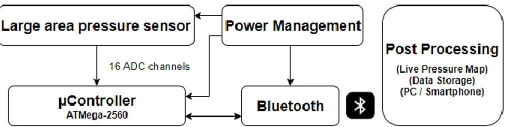
The proposed large area sensing system comprises three main units as shown in Fig. 3.1:
• Large area pressure sensor • Read-out electronics
• Post processing and data presentation
Read-out electronics consist of a microcontroller, Bluetooth module and a power management unit. In the current proposed design, the post-processing unit is a computer with data post-processing software such as MATLAB. However, it can be any smart device capable of processing and displaying pressure intensities.
3.1.1 Design of large area pressure sensor matrix
When a piezoresistive material is put under uniaxial stress, a narrowing of the distance between the conductive filler particles occurs and the con-ductivity changes in accordance with the applied force [53]. In the pro-posed design, there are 16 sensing elements in the large area pressure sen-sor, which has an area of 505 cm2. The horizontal and vertical dimensions
are 23.5 cm × 21.5 cm. The distance between each sensing element in the matrix is 5.5 cm and 3.0 cm in X and Y directions, respectively. These are the typical seating dimensions of a person for ischial areas. The sensor is usually placed inside or underneath the foam cushion. The assembly
18
quires a very thin and flexible pressure sensor to be able to tolerate me-chanical deformations due to movements of the wheelchair user. The pro-posed large area sensor comprises three sheets of PET (top, centre and bottom), where each sheet is 100 µm thick. The top sheet is printed with interdigital structures and interconnects with conductive Ag ink and op-erates as conductive layer. The bottom sheet is printed with carbon filler based blended inks that has both resistive and piezoresistive properties, and operates as sensing layer. The centre sheet is being used as a separa-tor between two layers and also functions as an adhesion/bonding be-tween the top and bottom sheets. The centre sheet has laser cut openings and patterns in arrangement with the top and bottom layers. In an idle state, both layers are isolated by 100 µm (centre sheet thickness) and when the pressure is applied on the surface of the sensing elements, both layers make a contact thus allowing the current to flow between the two sides of the interdigital structures. Further pressure allows more contacts result-ing in more conductresult-ing paths. Hence, the resistance decreases by applica-tion of force and this resistance is translated into pressure values with cal-ibration using a force gauge.
3.1.2 Fabrication of printed sensors and interconnects
The top layer of the sensor matrix is printed with Ag flakes-based ink, EDAG 725-A, which has a sheet resistance <15 mΩ/sq/25 µm and it is tem-perature curable in a convection oven at 120 °C for 20 minutes. A 7 µm Ag ink layer is manually screen-printed on a 100 µm PET sheet with a 100-40 (100 threads per cm, 40 µm thick) meshed screen. Methyl Ethyl Ketone (MEK) is used for removing any dust or fat particles from the PET sheets. After curing, the resistance between the two ends of the longest printed conductive line (215 mm) is measured as 16 Ω with a single coat-ing of Ag ink. With two wet-on-wet coatcoat-ings of the ink, the thickness is 12 µm and resistance is 12 Ω, and with three wet-on-wet coatings, the thick-ness is 14 µm and resistance is 8 Ω, respectively.
The sensing layer is printed using commercially available Loctite ECI 7004-LR, which is a low resistivity carbon particle-based inks and Loctite NCI-7002 non-conductive ink from Henkel AG & Co. The inks can be blended to obtain controllable ranges of electrical resistance. These inks are blended together with a 30 % and 70 % ratio, respectively to obtain an approximately 150 kΩ/sq/10 µm customized initial sheet resistance, which is observed as an optimal value (neither too conductive nor too resistive) for the scope of the design.
The blending is carried out at 100 rpm for 10 minutes to acquire a ho-mogenous ink composite for screen-printing. A 10 µm layer of this blended ink is printed on a 100 µm PET sheet using screen-printing with a 100-60 (100 threads per cm, 60 µm thick) meshed screen. All the inks used in fabrication, are temperature curable at 120 °C for 20 minutes and have an adhesion standard of ISO class 0 (ASTM class: 5B).
3.1.3 Design of read-out electronics
The initial data processing in the read-out electronics is carried out with an 8-bit Atmel ATmega-2560 microcontroller operating at 16 MHz. The data acquisition from pressure sensing elements is performed with six-teen dedicated ADC channels of 10-bit resolution of the microcontroller. In the design, each sensing element is scanned at a frequency of 10 Hz. The Bluetooth module (HC-06) is used in the read-out electronics for wireless data transfer over serial port profile (SPP) for sensor readings. The read-out electronics, along with the Bluetooth module, is mounted on a 2 cm × 5 cm PCB shown in Fig. 3.3.
20
The read-out circuitry is operated at 5.0 V and can be powered with a 3000-mAh battery pack for fully wireless implementation. A small boost converter is utilised, when the read-out circuit is operated with battery. The small form factor enables the sensor matrix, read-out electronics, and portable battery pack to easily fit inside the seat cushion. A twenty-pin flex cable of 0.5 mm pitch connects the sensor matrix to the PCB. A single sensing element draws a maximum of 0.56 mA current, when connected in a 5.0 V voltage divider configuration with high precision 10 kΩ resis-tors. The overall read-out electronics utilizes an average of 66 mA current. The voltage diver configuration is described by equation (2).
𝑉out= 𝑉in× 𝑅sensor
𝑅10k+ 𝑅sensor (2)
Fig. 3.4 presents the response and recovery time of a sensing element, when loaded and unloaded in terms of rise time and fall time in a 5.0 V voltage divider configuration with a 10 kΩ resistor of 0.01 % precision.
Figure 3.4: Response time for normal actuation of a sensing element. Figure 3.3: PCB design of read-out electronics (Front-side and Backside).
3.1.4 Sitting posture recognition
For processing of the data and designing the graphical user interface GUI, a MATLAB software package is used, in which the mapping of each dis-tributed pressure point is carried out to display pressure intensities in real-time by continuously updating the graph. A delay of 100 µs is given at the transmitter side for the reliable transfer of data. The overall screen refresh rate in the GUI is 200 ms.
The algorithm for sitting postures recognition can identify four un-balanced sitting postures, forward leaning, backward leaning, right lean-ing and left leanlean-ing, with leanlean-ing angles of about 25° and 35° from the straight (90°) natural sitting position of a seated person. It can also detect and recognize a balanced sitting position.
The classification of sitting posture is based on the total number of activated sensors, single sensing element values, the sum of all sensing element values, and the average of sensing element values, which are pro-cessed through a decision tree algorithm. This classification scheme is simple, provides good results and does not require extensive computing resources compared to support vector machine (SVM) [43] and k-nearest neighbors (k-NN) [44]. Fig. 3.5 show intensities of pressure over sensing elements, based on leaning positions.
(a) (b) (c) (d)
Figure 3.5: Screenshots of pressure intensities acquired at about 35° leaning angle. (a) Forward leaning (b) Backward leaning (c) Right leaning (d) Left leaning
4 Results
4.1
Characterization
The graph in Fig. 4.1 exhibits decreasing resistance values when individ-ual sensing elements receive an actuation from 1.0 N to 100 N. The graph is nonlinear and resembles an inverse power law. At a higher amount of pressure i.e. 50-100 N, marginal decrement in resistance steps take place. Four individual sensing elements are taken from printed large area pres-sure sensor and characterized to obtain a resistance graph as a function of force. The force data is obtained by a Lutron FG-6020SD dynamometer mounted on a translation stage and resistance data by an Agilent 34405A multimeter.
The result shows a nearly 8 % difference between the output values of four sensing elements. It is observed that a pressure exceeding 200 N/cm2 can cause irreversible deformation to sensor layers that results in
partial or total failure of sensing element. It is also noticed that when the sensor matrix is placed under the foam, the observed average pressure per single sensing element is between 30 N‒50 N for an able-bodied per-son weighing between 70 Kg‒90 Kg and sitting straight at 90°.
24
4.1.1 Drift
Drift is an unwanted variation that occurs due to mechanical instability and in some cases, environmental effects such as temperature and humid-ity. The main reasons for sensor drift are the electrical drift in the inter-connect system, the non-uniform mechanical stress at the sensor surface and structural surface tension after exertion of load. The drift is reversible if it occurs within the functional limits of the sensor. For the drift test, a constant load of 2.0 N, 5.0 N, 10 N and 25 N is applied on sensing elements for 60 minutes and up to 24 hours. A rubber-based actuator of 7 mm di-ameter and 3 mm thickness is used for sensor actuation. The resistance is logged at one sample per minute. The results for 60 minutes and 24 hours drift tests are shown in Table 4.1.
4.1.2 Environmental chamber testing
The sensor is also put under test for calculating the change in sensor char-acteristics due to variations in temperature and humidity. For this pur-pose, an environmental chamber (TESTEQUITY 1007H) is used and the temperature is varied while keeping the humidity constant. However, it is only possible to control the humidity level between temperatures rang-ing +10 °C and +85 °C. The drift effect is also present as these tests take up to 40‒50 minutes. The graphs in Fig. 4.2 displays the readings taken at different humidity and temperature settings for sensing units under 5 N and 10 N downwards force. The readings are taken about 25 seconds after the exertion of force. The test is conducted from a colder temperature to a hotter temperature and from a hotter temperature to a colder temperature in the environment chamber. The findings indicate a higher variation, while changing from colder to hotter temperatures due to the increasing influence of the drift factor. In the hotter to colder test, it displays a small
TABLE4.1 SENSOR DRIFT (%)
Time / Force 2 N 5 N 10 N 25 N 60 Minutes 3.89 5.01 5.30 1.45
drift and then an increase in electrical resistance due to colder tempera-tures. The sensor is also tested for a temperature above normal environ-mental conditions i.e. 90 °C, shown by a blue trend line in the plot.
4.1.3 Bending testing
To conduct the bending test, sensing elements are acquired from the large area sensor matrix. Six cylinders ranging from 6 cm to 1 cm are 3D-printed to conduct the test. It is observed that the sensing element maintains its functionality and stability up to a bending diameter of 2.0 cm. At a bend-ing diameter of 1.0 cm, the mechanical stress becomes too much and the 100 µm gap between conductive layer and sensing layer reaches a mini-mum, thus causing a false actuation reading while bending. However, this is temporary and recovers when the sensing element is released from the bending cylinder. Table 4.2 shows the percentage variation in re-sistance readings when a constant 10 N force is applied before, during and after bending.
TABLE4.2 BENDING TEST
Radius of cylinder 6 cm 5 cm 4 cm 3 cm 2 cm 1 cm
Test Pass Pass Pass Pass Pass Fail
During Bending % 1.37 1.91 2.40 3.63 5.89 -
After Bending % 0.15 0.26 0.43 0.68 0.97 1.25
26
4.1.4 Stretchable conductive tracks
Stretchable screen-printed conductive tracks on a flexible substrate can withstand high mechanical strain while maintaining good electrical con-ductivity. Straight track samples with a measured thickness of 12 µm and various trace widths are printed using a stretchable Ag ink ECI-1036. An 88 µm thick TPU stretchable film [41], is employed as a substrate. Four temperatures: 110 °C, 120 °C, 130 °C and 150 °C are chosen to cure the stretchable ink, where four curing times: 3, 10, 20 and 30 minutes, are used for each temperature. In total, 16 curing temperature-time combinations are used. Cyclic strain tests with 25 % and 50 % elongations are carried out in order to observe the variation in electrical resistance after being subjected to mechanical deformation and fatigue. The test setup is shown in Fig. 4.3. The results from elongation test indicate that a sample cured at 150 °C for 30 minutes provides a better conductivity even after multiple elongation cycles. The result of the elongation test to show variation in printed track resistance before and after 25 % and 50 % elongations are included in Appendix I. However, a few samples showed a tendency of stretching nonuniformly mainly due to slight thickness variation of the TPU substrate.
4.1.5 Surface morphology of printed samples
The surface morphology is carried out to obtain an insight into the inter-action between two printed layers when they make a contact. The samples are printed onto PET substrate. Fig 4.4(a) shows an SEM image of conduc-tive interconnect that is printed with Ag flake-based ink EDAG-725-A. A cross section analysis is also carried out to determine the quality and uni-formity of printed layer that is depicted in Fig 4.4(c). The sensing layer is also examined and Fig 4.4(b) and Fig 4.4(d) show the images for the sur-face and cross section of printed and cured carbon ink samples, respec-tively.
To investigate morphological changes within the stretchable printed samples, SEM images are recorded that are shown in Fig 4.5. The images show surfaces of samples that are printed with ECM-1036 stretchable ink onto the TPU substrate. Fig 4.5(a) shows an SEM image of a cured sample at 150 °C for 30 minutes in convection oven. Fig 4.5(b) shows an SEM im-age of a cured sample at 110 °C for 3 minutes. Although there is a
signifi-(a) (b)
(c) (d)
Figure 4.4: Morphology of printed samples.
(a) Micrometre sized Ag flake (b) Nanometre sized carbon particles
28
cant difference in the conductance of screen-printed tracks when meas-ured by a multimeter, it is nevertheless, difficult to observe a difference between two samples in SEM images. The outcomes of EDS analysis are presented in Table 4.3, that reveals a very little change in Ag particles con-centration between conductive samples. It is interesting to see the close-up image of a sample that has damaged conductivity due to overstretch-ing. A sample is prepared by stretching it and placing it on a sample mount. Fig 4.5(c) reveals that conductive paths are broken between Ag flakes while elastomeric binding material can also be observed in the im-age.
(a) (b) (c)
Figure 4.5 (a) SEM micrograph (SE) of a sample cured at 150 °C for 30 minutes (b) SEM micrograph (in-beam SE) of a sample cured at 110 °C for 3 minutes (c) SEM micrograph of a sample cured at 110 °C for 10 minutes, having damaged conductivity
(overstretched) TABLE4.3 ELEMENTAL ANALYSIS Sample /Element Ag % C % O % Cl % σ 110 °C for 3 minutes 85.8 8.0 3.7 2.6 0.7 150 °C for 30 minutes 89.3 7.8 2.1 0.8 0.9 Damaged conductivity 69.6 15.8 9.7 3.2 0.4
5 Discussions
5.1 Validity of
results
The main focus of the thesis has been on the fabrication of a large area pressure sensor, which is thin and flexible. The understanding of the in-teractions between functional materials (inks and substrates), would pro-vide a grounding for manufacturing printed electronics-based devices and sensors. The range and sensitivity of a pressure sensor can be tuned and optimized by adjusting the sheet resistance of pressure sensitive ink. The sampling and readings are carried out with calibrated measure-ment tools. It is found that the large area pressure sensor is providing satisfactory results within its sensor class [48], [49], [54]. The calibration of printed pressure sensors using a force gauge may require a second force gauge from another manufacturer for verification of calibration. While conducting the elongation test for stretchable interconnects, a slight nonuniformity in the thickness of TPU substrate can affect elongation over weaker areas and can therefore, affect the conductivity of overall printed track after elongations.
5.2 Limitations and possible improvements of
pro-posed large area pressure sensor
Limitations and shortcomings of this posture recognition technique in-clude a relatively small sampling set and limited number of test persons. This large area pressure sensor is only capable of measuring the pressure in a downward direction and cannot measure shear. The fabricated sensor cannot stretch and hence the functionality is limited to flat or semi-flat surfaces.
The designed prototype is currently using Bluetooth classic, which has a limited range and character support. It also requires some time to establish a connection to the host device. The module is going to be re-placed by BLE v5.0 so as to achieve power efficiency, improve data trans-fer rates, security and a longer range. It is worthwhile pointing out that, in order to attain more accurate insight about the functionalities and per-formance of the proposed large area sensor, test conditions can be broad-ened by including actual wheelchair users as volunteers and participants.
30
5.3 Ethics and impact on society
There are several important ethical and social aspects that need consid-erations.
5.3.1 Ethics
There are always fundamental ethical aspects to consider when the re-search deals with a patient’s data. The privacy of the patient’s data is very important. The researcher is bound to fulfil the privacy requirements as per regulations. Another ethical aspect is the disposal of waste electronics, as the waste including plastic and ink residuals that must be disposed properly at designated disposal stations.
5.3.2 General considerations
The developed sensors use plastic materials as substrate which may not be quite environmentally friendly material. Moreover, the inks that have been used to develop conducting and sensing layers might have hazard-ous effects on the environment. The solvents such as Acetone and Methyl Ethyl Ketone (MEK) employed for cleaning, must be used in a properly ventilated room. A warning sign can be placed at the entrance of a shared lab for possible side effects from these solvents.
5.3.3 Impact on society
The research findings do have a great impact on society as they provide a prevention measure against pressure ulcer development in wheelchair users. The pressure sensing system can also provide a similar solution for bedridden people. The pressure sensors developed can be effectively used to determine the sitting behaviour of a patient by measuring the dis-tributed pressure points. The large area sensor can, therefore, be used as a prevention measure and also for developing treatment plans if the pa-tient has already developed pressure sores [52]. The overall impact would be a lesser burden on hospitals, reduced nursing hours, medication costs and more importantly, the avoidance of ineffable pain that a pressure ul-cer patient will suffer. Hence, the wheelchair users as well as the individ-uals with longer sitting hours with a sedentary lifestyle and individindivid-uals such as drivers, gamers and office workers may be the primary benefi-ciary of such system.
6 Summary
Manufacturing of electronic devices through printing requires an under-standing of inks, substrates and application methods. The thesis aims to address important challenges regarding the fabrication and implementa-tion of large area pressure sensors for wheelchair users. The pressure sen-sors can be integrated into a powered wheelchair or can function as standalone pressure monitoring system. In summary, the contribution in the thesis presents a health care solution for wheelchair users that may assist in preventing the development of pressure ulcer and hence help re-duce the financial burden on the healthcare system.
6.1 Conclusion
The overall benefits of printed electronics are they are capable of provid-ing low-cost, easy production, simple integration, a thin form factor and flexible solutions for fabrication of integrated electronic circuits. The non-conventional electronics and new materials such as stretchable polymers, plastics and different fabrics have unlocked new possibilities in the elec-tronics industry. This research has presented a non-conventional, cost-ef-fective and flexible sensor design for a large area pressure sensing system, utilised in a wheelchair seat cushion by using screen-printing. This thesis, in general, has provided one solution regarding large area pressure sen-sors to be employed in healthcare for the prevention of pressure ulcers in wheelchair users.
Different transduction mechanisms are studied along with their com-plexity, response time, stability and repeatability. As per design parame-ters for thin and flexible printed sensors, the proposed pressure sensor is 320 µm thick, and each sensing element is capable of sensing a force be-tween 1 N up to 100 N. The designed sensor is characterized by investi-gating its parameters in terms of resistance, response time, recovery time, drift, durability and repeatability. The large area pressure sensor is slightly sensitive to ambient conditions. An algorithm for sitting posture recognition has been developed and it has demonstrated an accuracy of more than 80 %.
Recent advancements in printable and stretchable TPU sheets opened many doors to stretchable sensors and other electronic devices. As
dis-32
cussed in the section above, stretchable inks printed over stretchable sub-strates maintain their electrical conductivity parameters even after multi-ple elongation cycles, if the substrate and curing times are adequate. The outcome of the research work may open a way to investigate the possibil-ities of multi-layered stretchable printed pressure sensors.
6.2 Future work
Possible future investigations can be considered in order to handle the limitations associated with the proposed work. The new approach of us-ing stretchable printed pressure sensors would give more flexibility and comfort to wheelchair users. This large area pressure sensor can be used effectively as an insole pressure monitoring system for gait analysis as well.
The decision tree algorithm using sum values and mean values of sen-sors gives a fair accuracy of posture detection that is above 80%, but it can be further enhanced by the implementation of more complex machine learning algorithms. Moreover, to achieve a more detailed pressure dis-tribution data, additional areas in the wheelchair can be equipped with pressure sensors, such as the back rest, head rest, foot rest and arm rest. The number of sensors can also be increased so as to attain a higher spatial resolution, with subsequent extended possibilities for extracting infor-mation about the seated person. This will allow collection and integration of detailed data, which would be used to improve posture recognition ef-ficiency. Moisture and temperature sensors may be embedded along with pressure sensors. The read-out electronics can be made even more effi-cient using high-end integrated chips and communication modules. Fur-thermore, smart phone applications could be developed to facilitate health professionals for monitoring of pressure distribution as well as in creating alarm features.
Bibliography
[1] A. Kamyshny and S. Magdassi, “Conductive Nanomaterials for Printed Electronics,” Small, vol. 10, no. 17, pp. 3515–3535, 2014.
[2] S. Majumder, T. Mondal, and M. J. Deen, “Wearable Sensors for Re-mote Health Monitoring,” Sensors (Basel)., vol. 17, no. 1, p. 130, Jan. 2017.
[3] S. Khan, L. Lorenzelli, and R. S. Dahiya, “Technologies for printing sensors and electronics over large flexible substrates: A review,” IEEE Sens. J., vol. 15, no. 6, pp. 3164–3185, 2015.
[4] B. Medina Rodríguez, “Inkjet and screen printing for electronic ap-plications,” 2016.
[5] T. T. Yoshikawa, N. J. Livesley, and A. W. Chow, “Infected pressure ulcers in elderly individuals,” Clin. Infect. Dis., vol. 35, no. 11, pp. 1390–1396, 2002.
[6] I. Swain, “The Measurement of Interface Pressure,” in Pressure Ulcer Research: Current and Future Perspectives, D. L. Bader, C. V. C. Bouten, D. Colin, and C. W. J. Oomens, Eds. Berlin, Heidelberg: Springer Berlin Heidelberg, 2005, pp. 51–71.
[7] M. Clark, G. Cherry, D. Colin, and T. Defloor, Science and Practice of Pressure Ulcer Management. Springer, 2006.
[8] E. A. Kruger, M. Pires, Y. Ngann, M. Sterling, and S. Rubayi, “Com-prehensive management of pressure ulcers in spinal cord injury: Current concepts and future trends,” J. Spinal Cord Med., vol. 36, no. 6, pp. 572–585, Nov. 2013.
[9] J. Black et al., “National Pressure Ulcer Advisory Panel’s updated pressure ulcer staging system.,” Dermatology Nurs., vol. 19, no. 4, p. 343–9; quiz 350, 2007.
[10] L. E. Edsberg, J. M. Black, M. Goldberg, L. McNichol, L. Moore, and M. Sieggreen, “Revised National Pressure Ulcer Advisory Panel pressure injury staging system: revised pressure injury staging sys-tem,” J. Wound, Ostomy, Cont. Nurs., vol. 43, no. 6, p. 585, 2016.
[11] M. Stephens and C. A. Bartley, “Understanding the association be-tween pressure ulcers and sitting in adults what does it mean for me and my carers? Seating guidelines for people, carers and health &
34
social care professionals,” J. Tissue Viability, vol. 27, no. 1, pp. 2–9, 2018.
[12] W. Etafa, Z. Argaw, E. Gemechu, and B. Melese, “Nurses’ attitude and perceived barriers to pressure ulcer prevention,” BMC Nurs., vol. 17, no. 1, p. 14, Apr. 2018.
[13] C. Dealey, J. Posnett, and A. Walker, “The cost of pressure ulcers in the United Kingdom,” J. Wound Care, vol. 21, no. 6, pp. 261–266, Jun. 2012.
[14] R. Mishra and S. Bhattacharya, “Pressure ulcers: Current under-standing and newer modalities of treatment,” Indian J. Plast. Surg., vol. 48, no. 1, p. 4, 2015.
[15] E. Linder-Ganz, G. Yarnitzky, Z. Yizhar, I. Siev-Ner, and A. Gefen, “Real-time finite element monitoring of sub-dermal tissue stresses in individuals with spinal cord injury: Toward prevention of pressure ulcers,” Ann. Biomed. Eng., vol. 37, no. 2, pp. 387–400, Nov. 2009.
[16] R. Anderson, C. Kleiber, J. Greiner, L. Comried, and M. Zimmerman, “Interface pressure redistribution on skin during continuous lateral rotation therapy: A feasibility study,” Hear. Lung J. Acute Crit. Care, vol. 45, no. 3, pp. 237–243, 2016.
[17] "Printed Electronics Market Size To Reach USD 19.15 Billion By 2025." Market Research Reports & Consulting | Grand View Re-search, Inc. Accessed March 1, 2019. https://www.grandviewre-search.com/press-release/global-printed-electronics-market.
[18] J. Ahmad, H. Andersson, and J. Sidén, “Screen-Printed Piezoresistive Sensors for Monitoring Pressure Distribution in Wheelchair,” IEEE Sens. J., vol. 19, no. 6, pp. 2055–2063, 2019.
[19] X. Li, J. Sidén, H. Andersson, and T. Schön, “A Paper-Based Screen Printed HF RFID Reader Antenna System,” IEEE J. Radio Freq. Iden-tif., vol. 2, no. 3, pp. 118–126, 2018.
[20] A. Al-Halhouli, H. Qitouqa, A. Alashqar, and J. Abu-Khalaf, “Inkjet printing for the fabrication of flexible/stretchable wearable electronic devices and sensors,” Sens. Rev., vol. 38, no. 4, pp. 438–452, 2018.
[21] V. Correia et al., “Design and fabrication of multilayer inkjet-printed passive components for printed electronics circuit development,” J. Manuf. Process., vol. 31, pp. 364–371, 2018.

![Figure 2.1: Graphical representation of transfer printing process [22].](https://thumb-eu.123doks.com/thumbv2/5dokorg/5426471.139841/31.722.212.510.735.886/figure-graphical-representation-transfer-printing-process.webp)
![Figure 2.2: Stretchable electrodes using PDMS [43].](https://thumb-eu.123doks.com/thumbv2/5dokorg/5426471.139841/35.722.240.488.590.719/figure-stretchable-electrodes-using-pdms.webp)