BACHELOR THESIS IN
AERONAUTICAL ENGINEERING
15 CREDITS, BASIC LEVEL 300
School of Innovation, Design and EngineeringProject Solaris – Construction of Solar
Powered UAV Prototype
Author: Magnus Johansson Report code: MDH.IDT.FLYG.0240.2011.GN300.15HP.FT
i
Abstract
To control an un-swept flying wing is problematic in some ways. One of the problems is that when the wing experiences a disturbance in yaw, it does not, since it has no tail, generate any torque in the opposite direction as a plane with a vertical stabilizer does. This thesis is foremost aimed at exploring one particular solution to this problem.
One approach to this problem is to place the motors out on the wing and differentiate the thrust, to achieve the same torque as splitted elevons or a vertical stabilizer does. This is what NASA used on the flying unmanned wing HELIOS. Reducing the thrust on the right set of engines, and increasing the thrust on the left side can mean that the combined thrust is unchanged. And thus more fuel efficient, and increases endurance.
This project’s main goal has been to construct a half scale model of the school project flying wing Solaris, and to configure a control system for the differentiated thrust as used on Helios. Thereafter conduct flight testing and evaluate the controllability of the wing in a number of flight conditions, this to get a sense of the wings characteristics and which parameters one should adjust to get the best controllability as possible.
After numerous adjustments and test flights it was concluded that it is possible to construct and fly a wing in this configuration, with relatively simple means, with satisfactory results. That the torsional rigidity has great influence on the controllability were evident after the test flights. After redistribution of the components on the wing the conclusion could be made that the dihedral could be held within the structural limit of the wing.
The results of this thesis will contribute to the project Solaris at Mälardalens University in Västerås, Sweden. The project was carried out at Mälardalens University. The test flights were conducted at the former Air Force base F-15 Flygstaden and Mohed in Söderhamn, Hälsingland.
ii
Sammanfattning
Att styra en flygande vinge som inte har någon pilform medför vissa problem i form av att en sådan konfiguration ej ger något återbördande moment vid en störning i gir-led. Det finns flera sätt att lösa detta. Denna rapport är framförallt inriktad på att tillämpa en lösning på detta problem.
En lösning finns på Aerovironment's /NASA:s flygande vinge Helios, där dragkraften kan differentieras på höger och vänster sida. Detta gör att dragkraftsvektorn, i teorin, kan vara konstant och samtidigt ge ett återbördande moment vid en störning i gir-led.
Detta projekt har gått ut på att konstruera ett halvskala av projektet och flygande vingen Solaris, samt konstruera ett styrsystem som fungerar på ett liknande sätt som Helios. Därefter provflyga och utvärdera systemet i olika flygförhållanden. Detta för att få en uppfattning om hur systemet fungerar i luften och vilka parametrar som kan justeras för att få systemet att fungera så optimalt som möjligt.
Efter ett flertal justeringar och provflygningar kunde slutsatsen dras att det är möjligt att få en flygande vinge i denna konfiguration, med relativt enkla medel, att fungera tillfredställande. Att vingens vridstyvhet har stor inverkan på kontrollerbarheten kunde konstateras.
Efter komponentplaceringen på vingen justerats kunde även slutsatsen dras att uppböjningen av vingen kunde hållas inom ramarna för vingens strukturella styrka.
Projektet har utförts vid Mälardalens Högskola, och resultatet av detta arbete kommer ingå i projekt Solaris på Mälardalens Högskola. Testflygningarna utfördes vid F-15 Flygstaden och Mohed i Söderhamn.
iii Date: June-August 2011
Carried out at: Mälardalen University
Supervisor and Examiner at MDH: Gustaf Enebog
Lecturer and Program Coordinator of the Bachelor Program in Aeronautical Engineering School of Innovation, Design and Engineering Mälardalen University
iv
Nomenclature and Abbreviations
CHs - Cooper Harper Scale EPA - End Point Adjustment ESC - Electronic Speed Control PIO - Pilot Induced Oscillation LIPO - Lithium-Polymer
NASA - National Aeronautics and Space Administration UAV - Unmanned Aerial Vehicle
MAh - Millie Ampere Hours EMF – Electromotive Force
v
Preface
The Bachelors Program in Aeronautics, at Mälardalen University, last task for the student is to write a thesis about a subject that the student has chosen.
To build a half-scale of the wing Solaris and conduct flight testing is what I chose and this thesis is about this.
vi
Table of contents
Contents ...1 1 Introduction ...1 1.1 Background ...1 1.2 Purpose ...2 1.3 Problem formulation ...3 1.4 Scope of work ...4 2 Method ...52.1 Design and selection of components ...5
2.1.1 Cost estimate ...5
2.1.2 Design/construction ...7
2.1.3 Control System ... 10
3 Flight Testing Procedure... 13
3.1 Cooper-Harper Scale ... 13
3.2 Center of gravity... 14
3.3 Flight Testing Schedule ... 14
3.4 Results/Discussion ... 15
Flight test stage 1 of schedule ... 15
Flight test stage 2 of schedule ... 16
Flight test stage 3 of schedule ... 17
Flight test stage 4-6 of schedule ... 19
Conclusions/ Recommendations for future work ... 21
References ... 22
Acknowledgements ... 23
1
Contents
1 Introduction
1.1 Background
It is possible to control a flying wing in the z-axis in a number of ways. The Northrop B2 on figure 1 uses splitted elevons, where the elevons can act as air brakes separately out on the wings. This generates torque to turn the aircraft. A downside of this configuration is that the splitted elevons cause extra drag. This means that the engines must throttle up to compensate for the increased drag, and hence burn more fuel. In short, it is not optimized in an endurance viewpoint.
Figure 1, B2 Bomber with elevons splitted.
If it was made possible to fine-tune the thrust on each of the engines, it would enable control of the wing in the z-axis with just differentiating the thrust. This also translates to the need of having a fast throttle response, otherwise the control of the wing in the z-axis would become sluggish and the wing could become uncontrollable if the wind gusts would change to fast. If the workload on the pilot should be kept reasonably low, control must be automated to some degree to eliminate the need for the pilot to apply corrections, when flying in a straight line.
Flying wings without empennage have been used before with differentiated thrust as means of controlling the wing in yaw. Aerovironment/NASA Helios on figure 2 was a flying wing with this configuration.
2
1.2 Purpose
The main purpose of this project was to investigate and test if it was possible to fly and control a span loading flying wing with zero wing sweep, with only differentiated thrust as means of control about the z-axis (yaw), with a limited budget. Other interesting parameters that were to be investigated were how controllable the wing would be in pitch.
The objective was not to gain exact flight data, but to discover its flight characteristics and how these characteristics are a function of different parameters.
The results from this project are aimed at gaining knowledge of how the wing will perform to have a safer starting point for the full-scale version of Solaris, as well as to get an
3
1.3 Problem formulation
The challenging aspects of stability and control in pitch that inherently follows with an un-swept flying wing as well as the inherent issues of a semi span loader with its high moment of inertia due to its heavy wingtips (the evenly distributed mass along the span rather than concentration towards the center) both demands special attention. Besides these features we also want to try out a rather novel approach for control in yaw by differential motor power between left and right set of motors. All this calls for extra attention in testing before applying such feature on the solar-powered equipped version of Solaris. For this reason this student projects objective is to build and fly a half scale version of Solaris purely powered by batteries.
4
1.4 Scope of work
The project was divided into six stages, these stages are listed below.
1. Design a half-scale version of Solaris, including choosing suitable components including propulsion and control system.
2. Make a cost estimate and buy material and parts. 3. Build the model.
4. Suggest a schedule for flight testing. 5. Conduct flight testing.
6. Write a thesis about the project.
7. Make recommendations for future work.
5
2 Method
2.1 Design and selection of components
2.1.1 Cost estimate
To be able to make a cost estimate, I needed to know what electric components that was suitable for the wing. As the wing was to be flown in a five section wing configuration with motors placed on a pylon in the junctions between the wing sections, four motors was needed. The motors was to be brushless due to its better efficiency, hence four brushless speed
controllers were needed as well. A brushless speed controller uses back EMF signals from the motor to know the position of the rotor on the motor, this is why it was necessary to use one speed controller per motor, otherwise the speed controller would not know from which motor the signals are coming from. At this stage the wing was projected to have one battery pack on each wing pylon. To go further in selecting a suitable motor package, I a rough total weight estimate of the wing, with taking this information in consideration, MotoCalc was used to get an indicator what kind of motor/propeller and battery that would suit the prototype.
I knew that I was going to use five 9 gram HXT900 servos, four 2-3 cell lipo packs, four motors, four speed controllers, at least one gyro, 2.4 GHz Assan receiver, 5-7 meters of servo/ESC wire, and the build material for the wing main frame.
The foam to be used was cut and weighed, the pylons made of 2mm thick light plywood. The wood of which the plywood was composed of was not specified from Hobbyträ. But generally light plywood is composed of the woods Poppel, Okoumé or Ceiba.
The motor MotoCalc calculated to suit the wing was the PP-28-26-1200 (Figure 3), this motor is effective with a 8x4 propeller and a 3-cell lipo battery. The calculated input wattage per motor was about 110 Watts at cruise. MotoCalc also calculated the amperage to peak at 16.
6 Figure 3, MotoCalc results
The data from the PP-28-26-1200 was used to find a cheap alternative. The final choice was the HXM2730-1300 motor, and HKESC10A ESC: s. These ESC: s was chosen due to low weight, suitable max amp and an integrated BEC. 3s 500 MAh 20C lipos from the same store was used. Four of each was ordered.
The gyro used was the Blue Arrow Nano BA-G2J1 which only weighs 2.3 grams, this gyro has an update rate of 50Hz. The gain is adjustable by a potentiometer. This means that it is adjustable how much the gyro shall adjust the PWM signal per change in angle sensed. The cost of each component and the total cost are summed up in table 1.
7
Item No
Price per item (USD) Total (USD) Description Grand total (USD) HXM2730-1300 4 8,07 32,28 Motors 285,11 BA-G2J1 1 28 28 Gyro BV01 2 4,03 8,06 V-Tail Mix TGY8x38SF 8 1,2 9,6 Propellers HXT900 6 2,69 16,14 Servos T500.3S.20 5 5,79 28,95 Lipos
AM1002A 1 1,98 1,98 Gold Connector 007-00301x10 1 0,99 0,99 Pin Horn OR006-01002 1 1,64 1,64 Wheels, small OR006-00806 1 2,3 2,3 Main Wheels
Twill-18g 4 15 60 Glassfiber
Carbon tubes 4 12 48 4mm tubes
Shipping EMS 1 47,17 47,17 Shipping
Table 1, Financial cost estimate.
2.1.2 Design/construction
When designing the half-scale model of Solaris, some focus was put on keeping the wing design as simple as possible. The wing structure was not anyway the focus of the model and we also wanted to reduce complexibility and keeping a low number of build technique parameters that can result in a twisted wing. Also to shorten the build time, in case of a serious crash it would be relatively easy to make a new wing panel to be able to continue flight testing as fast as possible.
A balsa-plywood built-up wing was deemed too complex and work-intense. Thus, a foam-cut wing would be a good option to be used, figure 4 show comparison. Still, the wing would then need to be covered with something that would enhance its stiffness and to get a surface that will not scratch and break too easy. The covering material also needed to be able to resist compression on the top of the wing and resist tension on the bottom. Covering the wing with thin fiberglass proved to satisfy these requirements.
8 Figure 4, Typical sheeted foam core wing (left) and built up wing (right)
The airfoil to be used has previously been decided to be one called Phoenix (figure 5) and is the result of another student’s thesis (Reference [1]). Also, a hot-wire saw was built with constant wire tension to be able to cut out the raw foam and get a good repeatable result so that all five wing panels could be built identical.
Figure 5, Phoenix airfoil.
After the wing panels were cut the wing was covered with fiberglass. The fiberglass used was Twill that weighs 18 grams per square meter. The weight gain, including matrix, was 20 grams per wing panel, the rigidity of the panel was increased with a factor of four. The rigidity proved to be in the lower region of what is required to get a good performing wing, in terms of controllability. More about this later, in the results part.
The trailing edge elevons were cut out at 21% of the wing chord. This is 31mm in chord length for the elevons. This decision was taken by taking account of previous builds and by interpolating the chord percentage used for the elevons on flying planks found on the internet, which uses the Phoenix airfoil.
9 Cavities were cut out under the wing to accommodate the servos, HXT 900 servos were fitted to the wing sections with hot melt adhesive, then each wing panel was put upside down and the control rod and elevon control horn was glued in place to get a near perfectly centered elevon when the servos are in neutral.
The motors were fitted on a 4 mm hollow carbon fiber tube. The tubes were fitted to the pylons with zip ties at a angle of 2 degrees down measured from the wings mean chord line, this to get the motors pointing straight forward when the wing was flying un accelerated (with a 2 degree angle of attack). The tubes that the motors were fitted to had a length of 500 mm, this to enable fitting an empennage during the initial test flights. The excess tube also made it possible to adjust the cg. 500 mm long 4 mm diameter carbon tubes were also fitted to the top of the pylons, these tubes were slid into holes in the wing sections and connect the pylons to each of the wing sections. To prevent each pylon to rotate about this carbon tube, one
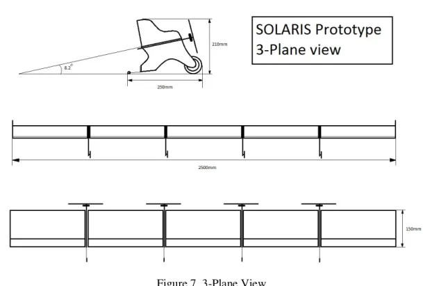
toothpick, as shown on figure 6, on each pylon was fitted close to the trailing side of the wing. A toothpick was chosen because in case of a crash it would break, and therefore let the wing section and pylon connected rotate. This will also absorb energy, and hopefully prevent extensive damage. Figure 7 shows the dimensions of the Solaris prototype.
10 Figure 7, 3-Plane View
2.1.3 Control System
To be able to differentiate the thrust, one could use an on board v-tail mixer or a mixer in the transmitter. But this project was aiming to have a system that could differentiate the thrust directly by itself based on the output from a gyro that could sense if the wing is yawing if it was not supposed to, and also of course to be able to throttle the motors to adjust the total amount of forward thrust.
One solution to this problem is to use dual v-tail mixers, coupled with an adjustable gain gyro. And these mixers are connected with the receiver and the four ESC: s. the rudder channel is connected to the v-tail mixer via the gyro. This means that when the pilot gives input via the rudder channel the gyro senses how much input the pilot gives and forwards this input to the mixer. When the pilot is not giving any input and the gyro senses that rotation is occurring, the gyro adjusts the pwm signal to the mixers, and makes one set of motors drop their rpm and the other set increase the rpm. The other channel on the mixers are connected directly by a y-cable from the throttle channel, and thereby making the mixer mix in throttle input as well. Figure 8 shows the layout of the motor control system.
11 Figure 8, motor control system
To get correct weight distribution along the wing two different configurations were tested. The ones that were tested first was the red and white boxes in figure 9, the final configuration are only the red boxes in figure 9.
12 Since the wing was to be flown in a five section configuration, there would have to be a mixer to make the control of the elevons symmetrical. Therefore a mixer was programmed in the transmitter, the two outer sets of trailing edge flaps got elevon programming and the center section was only used as elevator as seen on figure 10.
13
3 Flight Testing Procedure
3.1 Cooper-Harper Scale
The initial flight testing was to be conducted with an empennage, the reason for this is to make the flight testing as safe as possible since it was difficult to foresee its sensitivity in pitch. The Cooper-Harper (Reference [2]) scale as seen on figure 11 was used to rate each stage of the flight testing schedule.
14
3.2 Center of gravity
To find the correct CG for the model a wing section was used and test glided. More and more weight was added to the front of the section, and then retested. After a number of iterations the wing section flew with a good constant glide slope. This CG at 23.6% of the wing chord from the leading edge was to be used during the test flights and adjusted if needed.
3.3 Flight Testing Schedule
The flight test schedule will enable testing of the characteristics of the wing and control system in a number of stages. Each stage will be evaluated after it has been conducted. The Cooper-Harper scale was used to answer each test stage. To be able to go to the next stage in the schedule the previous stage must have passed with at least a 6 on the Cooper-Harper scale. The stages marked with an (x) are to be conducted after the empennage has been removed as well.
1. Taxi testing, ability to keep straight line at acceleration to rotation
2. (x) Take the wing up to rotation speed, check tendency to pitch change and observe how much v-shape is generated at this moment. This will tell how well the equipment is distributed along the wing.
3. (x) Take the wing up to rotation speed and perform a takeoff, fly at approximately 0.5-1 meters altitude for about 0.5-100 meters, reduce throttle and land straight forward. Evaluate the wings tendency to fly straight in yaw (zero beta angle) and how sensitive it is to pitch change.
4. (x) Take off and initiate a turn, observe the wings responsiveness to aileron input, if there is any aerodynamic coupling occurring. That meaning if there is any pitch change at initiation of input of aileron. After a 180 degree turn, level the wings and again observe the parameters that were checked at initiation of the turn.
5. (x) Initiate a turn and observe the ships ability to correct itself in yaw, give moderate rudder input during the turn and observe the ships response to this. Magnitude of the response and time to get response.
6. Maneuver the ship into final approach. Observe the pitch stability during adjustment of glide path.
15
3.4 Results/Discussion
Flight test stage 1 of schedule
A taxi runway at F-15 Söderhamn was used for this test.
The first test stage was to test the wing`s ability to keep a straight line when taxing.
Throttle was applied and the wing yawed a bit to the right, counter stick was applied and the yaw stopped but was over compensated to the left instead. Yaw compensation to the right was then applied and the wing yawed back to the right again. It was very hard to avoid PIO in yaw. And the test run was aborted. At this stage yaw control was rated a 9-10 on the CHs. The EPA was reduced to about 25% on yaw and the gyro gain was increased to 60% and the test was conducted again
At this stage, there was a smaller need to compensate since the wing accelerated in a straighter line. Even though some PIO was evident when yaw was being corrected, the gyro control was more noticeable now and the wing was able to taxi on the taxiway. The CHs rating at this stage was between 4 and 5.
The gyro gain was further increased to 65% and EPA on yaw reduced to 19% and the test was once again done.
At these settings the wing responded well to yaw input and corrected itself adequate, especially at higher speeds. The system response is not as good as a non-span loader with a high tail volume, this is due to the artificial stability systems need to first sense the yaw, and then utilize the differentiated thrust to compensate the yaw. The time this takes and the time for the motors to rev up and down are greater than the immediate change in lift a vertical stabilizer generates when the wing or plane experience yaw. But still controllable and the fact that the wing was getting more stable at higher speeds allowed the testing to move on the next stage of the flight schedule.
The final CHs rating was 3.
Relevant settings:
Initial gyro gain was set at 50% and later changed to 65%. Initial EPA on the yaw-channel was initially set at 40% but later adjusted to 19%.
16 Flight test stage 2 of schedule
The second test stage was aimed at getting a sense of the weight distribution along the wing, this to get correct dihedral when in-flight. This is very important since there is no stiff spar along the wing, so the ability to withstand bending of the wing is somewhat limited. The tendency for the wing to pitch up was also to be examined during this test.
The wing was accelerated to very high speed at the taxi way. As the speed increased more and more the higher the wingtips went. It was evident due to the very large dihedral shown on figure 12 that the wing needed to get its weight distribution adjusted. And when the speed was up, the wing showed no tendency to want to rotate or lift.
The original component placement was as following: One battery, esc, servo and motor at each pylon. Gyro, v-tail mixers and receiver was placed on the middle two pylons. When adjusted the inner lipo batteries were removed and the power cables on each pair of esc:s was parallel connected. The outer lipo batteries were then connected to these cables by gold plated connectors.
Figure 12, wing with large dihedral
The test showed that the wing`s alpha angle was too small when sitting on the wheels, the tail wheels prevented the wing from getting up on the main wheels and then let the elevators increase the alpha. This meant that the pylons had to be modified as seen on figure 13 to get the tail wheels higher. The vertical line on the picture below is the new mounting point for the tail wheel. The original angle was 4.4 degrees and after the modification the angle was
17 Figure 13, modification lines on pylon.
After the modifications were done, the test was conducted again. This time, as the speed increased, the wingtips lifted about 3-4 cm and the wing got up on its main wheels. Moderate up elevator was applied and the wing lifted about 40 cm off the ground, then throttle was reduced and the wing landed. This meant that the weight distribution was correct and the wing was responsive to elevator input. The wing was ready for the next stage of flight testing.
Flight test stage 3 of schedule
The third stage of flight testing´s purpose was to further examine the wing`s sensitivity to pitch change in flight. The ability to fly in a straight line was also a parameter to be tested here.
The wing was accelerated to take-off speed and rotation was initiated. Straight forward flight was stable until a wing gust from the side made the wing roll to the left, right aileron was applied but the wing was not responding. The wing flew off to the left and throttle was reduced and the wing crashed to the ground, breaking two pylons and toothpicks that kept the wing sections from rotating in-flight.
The wing was repaired and the flight video was examined, but it was hard to determine why the wing had behaved as it had based on the video.
Since the wing was to be flown without any empennage, and the wing was responsive in pitch already, the horizontal stabilizers were removed.
18 I was suspecting that they had an impact on the wings control in roll since there were two empennages that were not connected to each other.
A new test was conducted; as the wing lifted the pitch control was still good, but more
sensitive with the horizontal stabilizer removed. Some control in roll was observed for a while but then it started to roll to the left again. Full left aileron was applied but only moderate response was experienced. Right rudder was applied and the wing corrected itself for a brief moment until it stalled and went for the ground. A large amount of elevator was applied just before impact and the wing stalled close to the ground. The only thing that broke was a toothpick which was easily replaced at the field.
At this point I rated the performance of the wing in roll-control at a 9-10 on the Cooper-Harper scale.
I increased the servo throw on aileron to 100% to 140% and reduced the elevator throw from 100% to 75%. Exponential was also added to the elevator channel, the amount exponential added was -25%.
The test was conducted a third time, and this time the wing was more responsive than before in aileron correction maneuvers, I also realized that the previous flights had been performed with too much throttle applied. As I reduced the throttle to about 20-30% airspeed went down considerably and the wing responded in a much better manner than before, which can indicate that the sensitivity to over speed are related to a aeroelastical problem. This was later
confirmed when examining a picture taken during the test flight, see figure 14. The pitch sensitiveness was also reduced and improved
At this stage I had gained the knowledge of some of the wings characteristics and in which speed range it works best. When the wing was flying at this lower speed I rated this test stage as a 2-3 on the Cooper-Harper scale.
Relevant settings:
The initial aileron and elevator EPA were set to 100%, and the elevator exponential was set to 0%. At the end of this test stage the aileron EPA was set to 140%, the elevator EPA set to 75% and the elevator exponential -25%
19 Figure 14, wing at over speed. The wing is noticeable twisted.
Flight test stage 4-6 of schedule
Flight test stage 4 to 6 were somewhat coupled since once the wing had taken off and made a turn, it has to follow thru and land as well.
The wing was accelerated and lifted shortly after rotation was performed. Speed was kept down and a left turn was initiated, the wing responded well to the aileron input and no pitch change was observed. Wings were leveled out after the wing had turned approximately 180 degrees. Also this time, the wing responded well to the aileron and elevator input.
After flying in a straight line and downwind I had some difficulties judging the wings airspeed, and as I initiated the right turn in to the wind aileron responsiveness were lowered. This meant that the airspeed was too high and I reduced throttle and aileron effectiveness was regained. As previously mentioned, the over speed problem originated from when the pilot deflected the right side elevons up (when making a right turn) the high aeroelasticity of the wing made the right half of the wing to pitch up. This makes the right wing generate more lift due to the increase in alpha and is the opposite effect the pilot is expecting.
As I was flying towards me I made another right turn to get in to the final approach, this time I applied some rudder in the turn and the wing responded well to this input as well, throttle was reduced and I landed the wing on the asphalt with no problems.
20 At this point I felt confident to take away the vertical stabilizers as well and conduct a full flight (test stage 4-6) with the wing in its final configuration.
The vertical stabilizers were removed, and the crosswind had picked up to 5 m/s.
The wing was accelerated and rotated when flight speed had been attained, this flight was filmed from behind at take-off. The crosswind made the wing want to yaw left in to the wind, but after 2-3 seconds the control system for the motors had fully corrected the yaw and kept the wing flying in a straight line without pilot input. A 180 degree right turn was performed with no control issues what so ever. Now the wing was flying in crosswind from the right but this was not noticed much from a pilot´s perspective. Mild corrective input was given due to some turbulence when fling in a straight line, I performed another right turn and flew the wing back to the airstrip. Every turn needed little to no rudder input, I turned right again and lined up the wing for landing. Throttle was reduced and the wing landed successfully.
I rated the wing´s overall controllability to a 2-3 on the Cooper-Harper scale, which must be seen as a great success. Figure 15 shows the wing at runway 29 after the completed flight testing. Some test flights will be available on YouTube from the user “aerodynmag”.
Figure 15, Solaris prototype. This concluded the flight testing
21
Conclusions/ Recommendations for future work
The goal of this project was to examine how a flying plank behaves and to gain knowledge about the characteristics of the automated control system in yaw for the motors.
It was a time consuming task to perform the flight testing, since once a major modification had to be done it could most often not be made out on the field. And once the modification had been done, there could be up to two weeks before the weather conditions allowed more testing.
The response time of the control system is a function of the thrust of each propulsion unit which in turn depends on propeller size and how powerful the motors are, also gyro-response time of course. But smaller propellers and too powerful motors mean that the propulsion will get inefficient. Before the construction of a full-scale version of Solaris, or any other flying plank with no empennage, further studies should be performed to find the best combination of motor power/propeller size and overall efficiency of pure forward propulsion to get the best endurance possible.
The components used for the control system were all of-the-shelf components that totaled about 200$. This shows that it is possible to control a flying wing in this manner with relatively cheap components.
A big advantage with a span loading wing is that the wing construction does not have to be very resistant to bending forces, and this means that a wing with a high aspect ratio can be constructed light. This is the case with this project, but another problem arises with a light construction like this and that is that the torsional stiffness is also reduced. This means that the wing will have a relatively narrow flight envelope due to being sensitive to over speed. The wing in this project experienced over speed on several occasions and aileron input effect was totally lost. Future constructions need to take this into consideration when constructing the wing because this can lead to a catastrophic failure and destruction of expensive equipment.
22
References
[1] Mikis Tsagarakis, Project Solaris - Analysis of airfoil for solar powered flying wing UAV. http://mdh.diva-portal.org/smash/record.jsf?pid=diva2:450812
23
Acknowledgements
I would like to thank Gustaf Enebog for proposing a very interesting project.
Thank you Aragorn AALL and Niklas Sjöström for the support with camera equipment, filming and photographing most of the test flights.
Thank you Tsagarakis for evaluating airfoil for Solaris and presented the winner to me so I could build the Solaris half scale with the correct airfoil.
24
Appendices
Airfoil Phoenix coordinates.
Phoenix 1.00000 0.00091 0.99000 0.00146 0.98000 0.00203 0.97000 0.00261 0.95000 0.00388 0.92500 0.00571 0.90000 0.00779 0.87500 0.01005 0.85000 0.01245 0.82500 0.01498 0.80000 0.01760 0.77500 0.02029 0.75000 0.02304 0.72500 0.02586 0.70000 0.02872 0.67500 0.03163 0.65000 0.03458 0.60000 0.04051 0.55000 0.04639 0.50000 0.05205 0.45000 0.05733 0.40000 0.06200 0.35000 0.06577 0.30000 0.06814 0.27500 0.06863 0.25000 0.06855 0.22500 0.06781 0.20000 0.06631 0.17500 0.06396 0.15000 0.06068 0.12500 0.05638 0.10000 0.05093 0.07500 0.04415 0.05000 0.03557 0.02500 0.02402 0.02000 0.02109 0.01500 0.01779 0.01250 0.01595 0.01000 0.01395 0.00750 0.01174 0.00500 0.00921 0.00250 0.00611 0.00100 0.00362 0.00000 0.00010 0.00100 -0.00259 0.00250 -0.00373 0.00500 -0.00471 0.00750 -0.00532 0.01000 -0.00576 0.01250 -0.00610
25 0.01500 -0.00639 0.02000 -0.00685 0.02500 -0.00721 0.03500 -0.00777 0.05000 -0.00835 0.07500 -0.00907 0.10000 -0.00971 0.12500 -0.01032 0.15000 -0.01089 0.17500 -0.01143 0.20000 -0.01195 0.22500 -0.01243 0.25000 -0.01288 0.27500 -0.01331 0.30000 -0.01371 0.35000 -0.01443 0.40000 -0.01506 0.45000 -0.01561 0.50000 -0.01607 0.55000 -0.01641 0.60000 -0.01654 0.65000 -0.01638 0.67500 -0.01617 0.70000 -0.01585 0.72500 -0.01542 0.75000 -0.01487 0.77500 -0.01420 0.80000 -0.01340 0.82500 -0.01247 0.85000 -0.01139 0.87500 -0.01017 0.90000 -0.00880 0.92500 -0.00726 0.95000 -0.00554 0.97000 -0.00402 0.98000 -0.00323 0.99000 -0.00242 1.00000 -0.00161