Deriving ECA-rules from timed-automata specifications.
(HS-IDA-EA-02-201)
AnnMarie Ericsson(b99anner@student.his.se)
Institutionen för datavetenskap Högskolan i Skövde, Box 408
S-54128 Skövde, SWEDEN
Final Year Project in Software Engineering, Spring 2002. Supervisor: Robert Nilsson
Deriving ECA-rules from timed-automata specifications.
Submitted by AnnMarie Ericsson to Högskolan Skövde as a dissertation for the degree of B.Sc., in the Department of Computer Science.
2002-06-06
I certify that all material in this dissertation which is not my own work has been identified and that no material is included for which a degree has previously been conferred on me.
Deriving ECA-rules from timed-automata specifications.
AnnMarie Ericsson (b99anner@student.his.se)
Abstract
Real-time systems are required to answer to external stimuli within a specified time-period. For this to be possible, the systems behaviour must be predictable. The use of active databases in real-time systems introduces unpredictability in the system, e.g. due to their use of active rules. The behaviour in active databases is usually specified in ECA-rules. Sets of ECA-rules are hard to analyse, which implies that the behaviour of the ECA-rule set is hard to predict.
The purpose of this project is to evaluate the ability to support the development of a predictable ECA-rule set. Using a formal method for the specification task is desirable, since a formal specification is analysable and can be proven correct. In this project, timed-automata are used for specifying the systems behaviour. A method for deriving predictable ECA-rules from a timed-automaton specification is developed, and successfully applied on a case-study specification. For this case-study specification, a set of ECA-rules preserving the analysed behaviour of the timed-automata specification is derived.
Contents
1
Introduction ... 1
2
Background ... 2
2.1 Real-time systems...2
2.1.1 Time triggered systems ...2
2.1.2 Event triggered systems ...2
2.2 Databases in real-time system environments ...2
2.2.1 Requirements on real-time databases ...3
2.2.2 Active database management systems (ADBMS)...3
2.2.3 ECA-Rules ...4
2.2.4 ECA-rules in DeeDS...5
2.2.5 Problems with ADBMS ...6
2.3 Formal methods ...7
2.4 Finite state machines and Finite automata ...8
2.4.1 Overview of state machines and automata...8
2.4.2 Finite-state automaton example...8
2.5 Timed automata...9
2.5.1 Overview of timed automata...9
2.5.2 Timed automaton example...9
2.5.3 UPPAAL...10
2.6 Preserving the systems specified behaviour...12
3
Problem description... 13
3.1 ECA-rules in real-time systems...13
3.2 Formal system specification...13
3.3 Use a formal specification to formulate ECA-rules ...13
3.4 Project aim and hypothesis...14
3.5 Objectives...14
4
Addressing the objectives ... 15
4.1 Method alternatives ...15
4.2 Methods used to reach the objectives ...15
5
An ECA-rule derivation method ... 17
5.1 Overview of developed method ...17
5.2.1 Specify the application...19
5.2.2 Verify the specification...20
5.2.3 Derive ECA-rules from the specification ...21
5.2.4 Verify the behaviour of the rules with respect to the model...23
6
Production cell case-study ... 24
6.1 Specifying the production cell...24
6.1.1 Structure of the production cells rule set. ...25
6.1.2 Timed-automaton specification...25
6.2 Verify the timed-automaton specification...27
6.2.1 Absence of non-termination behaviour...28
6.2.2 Ability to fulfil the timeliness requirements ...29
6.2.3 Ability to limit the depth of cascade triggering...30
6.3 Derive ECA-rules from the specification...30
6.4 Verify the behaviour of the ECA-rules with respect to the model ...38
7
Analysis of the method for deriving ECA-rules ... 41
7.1 Extract a method for deriving rules from timed-automata...41
7.1.1 Method analysis...41
7.1.2 Analysis of the use of timed-automata and Uppaal...42
7.2 Derive ECA-rules from a timed-automaton specification ...43
7.3 Ability to derive ECA-rules from timed-automata in the general case. ...43
7.3.1 Limitations of timed-automaton...44
7.3.2 Guidelines for specifications...44
7.4 Related work ...45
7.4.1 How to construct predictable rule sets...45
7.4.2 A Uniform Approach for Supporting Active Database Features ...46
7.4.3 Extracting ECA-rules from UML...46
7.4.4 The existence of refinement mappings ...46
7.4.5 Rule termination analysis based on Petri nets...47
8
Conclusion ... 48
8.1 Summary of results ...48
8.2 Discussion ...49
8.3 Project conclusions ...51
8.4 Fulfilment of the project hypothesis ...51
8.5 Contributions...52
9
Acknowledgement... 54
10
References... 55
Appendix A... 57
Appendix B... 60
Appendix C... 70
Appendix D... 87
1
Introduction
Application development of real-time systems using active databases are currently immature, one reason for that is the lack of suitable specification formalism for active database behaviour. Active databases may be able to respond actively on changes in the environment; acting on detection of inconsistent data etc. However, these features might introduce unpredictable behaviour to the system. This implies that the behaviour of a real-time system using active databases needs to be specified in a way that captures the events that might be triggered by the database. ECA rules (On Event If Condition Do Action) are used as a building block for specifying the reactive behaviour of an active database. However, the ability for rules to depend on each other makes it hard to track the behaviour of an occurred event specified by ECA-rules (Falkenroth & Törne, 1999). This is not acceptable in real-time systems where the executions of transactions must be predictable.
Formal methods provide a framework for modelling, and analysing the behaviour of systems. They provide the ability to reason about the systems behaviour in an unambiguous mathematical way, and the ability to prove that the system model meets the certain systems requirements. It is desirable to specify real-time systems using formal methods, since real-time systems often are used for monitoring and controlling objects in an environment where failures may cause a disaster. Timed-automata models introduced by Alur and Dill (1994) provides a way to specify the behaviour of a system as well as capturing the systems time constraints, using a finite-automaton extended with a set of clocks. The CASE tool Uppaal (Larsen et al., 1997) provides the ability to specify the systems behaviour in timed-automata models, to simulate the behaviour of the system before it is built, and to check the model for invariant and reachability properties.
The aim of this project is to evaluate the ability to derive ECA-rules from a timed-automaton specification while preserving the systems specified behaviour. We investigate how to exploit the benefits of a formal and analysable model, such as timed-automata, for deriving sets of ECA-rules, which avoid introducing unpredictability in active real-time databases. A control program of a production cell is specified and analysed in Uppaal, and used as a base for deriving the ECA rules possible to implement in the forthcoming system. Deriving the rules from a timed automaton specification, keeping the systems behaviour (although expressed in ECA-rules instead of timed-automaton) makes it possible to analyse the set of ECA-ECA-rules, and discover undesired behaviour like uncontrolled cascade triggering, and cascade cycles in the model.
The main result of this study is a suggestion of a method for deriving ECA-rules from timed-automata specifications. Since the automaton specification is verified in a formal language, it is possible to prove that the specification fulfils certain requirements. This is important since the specification is derived into ECA-rules, and the specified behaviour should be preserved during the transformation into rules. Since the specification is formally verified, and the transformation is preserving the specified behaviour, the derivation of ECA-rules from a timed-automaton specification potentially reduces the unpredictability introduced in systems by the use of ECA-rules.
2
Background
2.1
Real-time systems
Real-time systems are characterized by their need to meet specified deadlines. The correctness criterion of the system depends on both the logical behaviour of the system, and its ability to meet its deadlines. The harm of a missed deadline depends on the nature of the application, and the deadline itself. A deadline can be categorized in hard (hard essential and hard critical), firm, and soft depending on the harm caused by a missed deadline. It can be anything from the produced data itself being useless to the system (soft deadline), to causing a dreadful disaster (hard critical deadline) (Eriksson, 1997).
2.1.1 Time triggered systems
In a non-deterministic concurrent program, independent processes may execute in any order, and still produce the same result. However, the execution orders may have very different ability to meet the programs temporal requirements, which makes it necessary for a real-time system to restrict the non-determinism found within concurrent systems. This process is known as scheduling, and in general it provides the features of an algorithm for ordering the use of system resources, and a means predicting the worst-case behaviour of the system when the scheduling algorithm is applied (Burns & Wellings, 1996). A scheduling scheme can be either static or dynamic. A static scheduling is appropriate for a time-triggered system. In such systems the resource requirements and time constraints are known a priori, and their worst-case behaviour is predictable. The time-triggered model is the classical approach for achieving temporal correctness in a system. The disadvantages with this model are the need to always allocate the resources for worst-case behaviour and the need to reanalyze, re-test and re-schedule the whole system if some system parameter has to be changed.
2.1.2 Event triggered systems
The dynamic scheduling may be used for systems referred to as event-triggered systems. The behaviour of an event-triggered system is determined by the current state of the system, and the incoming requests e.g. the system must answer on sporadic events from the environments, which might occur anytime (Kopetz & Verissiomo, 1993). The event triggered systems does not suffer from the disadvantages appearing in a time triggered system, however, with dynamic scheduling the number of events arriving to the systems at a certain time is not known a priori. This might lead to a situation where the arriving number of events is too big for the system to handle, and an overload situation occurs. This situation can be resolved e.g. by dropping task with low priority, or not allowing more tasks into the system while the overload condition exists (Eriksson, 1997).
2.2
Databases in real-time system environments
Real-time database systems bridge over two different areas in computer science:
real-time systems and database systems. Traditional databases have not been designed with
real-time constraints in mind, they may be efficient, but that is not sufficient since a real-time system also must be predictable. A real-time system must have predictable
execution times; otherwise a task can never be guaranteed to meet its deadline (Eriksson, 1997).
2.2.1 Requirements on real-time databases
Transactions in a conventional database should possess several properties. These are often referred to as the ACID properties (Atomicity, Consistency preservation, Isolation, and Durability). However, for a transaction in a real-time database system these properties are not enough. Since real-time systems typically must deal with an external environment, where time plays an important role, the external and temporal consistency of the database must also be considered. According to Locke (1997) these properties are defined as follows:
2.2.1.1 External consistency
External consistency is concerned about that the data being stored is representing the state of the real world artefacts at any point in time (e.g. if the database contains an aircraft velocity of 425 knots, the actual aircraft velocity is 420 ± .01 knots).
2.2.1.2 Temporal consistency
Temporal consistency is concerned about that the data being stored is representing the accurate state of the real-world artefacts, at a point in time acceptably close to the time at which other related data elements are known to be accurate (e.g., if the target latitude was measured at a time of 215.06217 seconds, the longitude was measured within 20 µs of that time.)
According to Ramamritham (1993) the temporal consistency constraint can be further divided in absolute consistency and relative consistency. The absolute consistency refers to the ability to keep the database consistent with the actual state of the related entity in the environment. This means that data stored in the database are typically valid for a defined duration, often referred to as the absolute validity interval (avi). The length of the avi depends on the environment e.g. the valid interval of the stored position data for a robot may depend on how fast the robot is moving, and how precise the data must be. Relative consistency refers to the temporal consistency between data used to produce other data. If e.g. both the temperature and the pressure in a tank are needed to produce output data, the temperature and pressure must both have been measured within a specified time period.
A disadvantage that comes with the use of a database in a real-time system is that it adds unpredictable behaviour to the system. According to Ramamritham (1993) the major sources of unpredictability are that the execution of a transaction may depend on the data values, resource conflicts, dynamic paging and transaction aborts.
2.2.2 Active database management systems (ADBMS)
In traditional database systems nothing happens unless a database action is explicitly requested by an application. Traditional databases are not capable of taking actions on their own, e.g. in terms of consistency maintenance. This is appropriate for simple systems, but in larger systems the applications using the database must spend a big effort performing these operations on the database. For an application to detect if something important has happened in a regular database, the database must be polled for data, and all constraints and consistency checks must be implemented in the application. This leads to a very large overhead if the database is polled too frequently
(Eriksson, 1997). Instead of loading every application with the burden of performing these tasks they can be transferred to the database management system. This demands the use of an active database system. Such systems can be classified as event-triggered systems and according to Eriksson (1997) this approach has the following advantages:
• Each update of a constraint only needs to be done centrally in the database manager, and not in each application.
• Since constraints are defined centrally they are the same for all applications. No two applications can have inconsistent constraints.
• A new application does not need to be programmed with all checks before start-up, since all information already is stored in a centrally maintained database manager.
2.2.3 ECA-Rules
Using rules to specify actions that are automatically triggered by certain events is a convenient way to express the active behaviour of the database. The concept of Event-Condition-Action (ECA) rules (on event E, if condition C is true, then trigger action A for execution) is used as a building block for specifying reactive behaviour in active databases (Andler & Hansson, 2001).
Event
The event part of the rule determines when the rule should be evaluated. The event (or events) that trigger a rule might e.g. be as simple as a database update operation or a temporal event. An example of a temporal event would be an event specified as a periodic time, such as: Trigger this rule every Monday at 11:20. However, the detection of an event may be quite complicated, it is for example possible to use hardware and software sensors for event detection in the environment, and to let the event carry parameters, for example a timestamp denoting the time of the event (Eriksson, 1997).
According to Mellin (1998) events may be assembled in composed events. A composed event consists of events combined by event operators (disjunction, conjunction, sequence, and various interval operators). Five different event parameter contexts are identified for composite events; they are recent, chronicle, continuous, cumulative and general. In the chronicle context events are consumed in their detection order. E.g. if more than one event (e1, e2, e3) is detected, of a type (E1) that is composed by a conjunction operator with another event (e5) of type (E2), the first occurrence of the type E1 will be used, and the composite event has occurred as the events e1 and e5 has occurred. In the recent context, only the most recent instances of a given event are used, earlier instances of that event type are thrown away.
A composite event are initiated by an initiator event, in a composite event (Ec) defined as a sequence of E1;E2;E3, an event e1 of type E1 initiates the composite event Ec. The composite event Ec is raised by the occurrence of the terminating event e3 of type E3.
Condition
The condition part of the rule determinates whether the action shall be executed or not. Once an event has occurred, the condition must be evaluated. If the condition is true the action will be executed. The event indicates the need to check, whereas the condition determines what to check. A condition may be a simple logical operation, for example “updated value x is larger than y”. Another example of a condition may be a query to the database, or an arbitrary function, which returns true or false (Eriksson, 1997).
Action
The action to be executed might e.g. be database operations such as deletion, update, transactions, or a sequence of SQL statements, but it may also be an external program that will be automatically executed, or external actions such as signalling an alarm, or launching missiles (Eriksson, 1997).
Although the ECA model may be appropriate for systems with periodic events, the constraint on the real-time system to be predictable implies that the transaction must be completed in time. According to Ramamritham (1993) constraints on completion times and delays can be specified with the following adjustments to the ECA rule:
ON (x seconds after event) IF (z not completed)
DO (within t seconds action w)
In the example x and t denotes time in seconds, z denotes a task, or a set of tasks, and w denotes an action, or a set of actions to be taken within t seconds.
2.2.4 ECA-rules in DeeDS
The implementation of ECA-rules varies in syntax and semantics. In this project, the method for deriving rules and mapping rules from timed-automata is in focus. The syntax of the resulting rule-set could be any commercial or academic ECA-syntax. In this project we limit our evaluation to the ECA-rules introduced in the rule manager of DeeDS (Distributed Active Real-time Database System) (Andler, et al., 1995). Another interesting syntax is SQL3, however, there are no available real-time databases that currently support SQL3 and according to Gorman (2001) “... there is no longer a well defined practically implementable subset of SQL features that can be proven via conformance tests”. In DeeDS, ECA-rules are specified in a high level notation, and then parsed in to C code, which can be used by the rule manager (Eriksson, 1998). In this project the behaviour specified in timed-automata will be transformed to the high level ECA-notation proposed by Eriksson (1998), which is an extended form of ECA-rules. The purpose of the extension is to be able to specify temporal attributes, such as deadlines and execution times. According to Eriksson (1998, p. 70) a rule is specified using the following syntax:
extended_rule = rule [rule_name][operation_modes][precedence] on event_spec
[if condition_spec] do action_spec [or action_spec]
A simplified description of the extended_rule will be given here, for further details see Eriksson (1998). In the extended_rule rule_name is an identifier of the rule, and
operation_modes define which modes of operation the rule is associated with. An
operation_mode has one, or several rules associated with it, and only one operation_mode can be active at the same time. Precedence defines if the rule is specified to be executed before, or after other specific rules triggered by the same event. In this way it is possible to restrict the execution order of the rules. An example of an event_spec may be “event update_temp is after temp_sensor.update” which specifies that the event “update_temp” is triggered after the method “temp_sensor.update” has executed. The condition specification is optional. If no condition is specified, the condition evaluates to true as an event-action rule. The condition specification may be a logical expression, or a method call which return true or false. The action part of the rule may be specified in any language supported by the system. However, temporal information and constraints (e.g. deadline time, latest start time, and execution time duration) must be specified to support timely executions of actions.
2.2.5 Problems with ADBMS
Adding the use of active rules to a database is not an area free from problems. There has been a lot of research in the area of deriving rules, and constructing rule sets (see e.g. related work in section 7.4). The main problem is that rules may depend on each other, and the systems behaviour is really hard to specify even for a small set of dependencies between rules. An example of dependencies between rules is the cascade triggering concept, where the execution of a rule might trigger another rule. This behaviour may be correct, but to guarantee the predictability of cascade triggering it is necessary to analyse the rule set to determine which rules may trigger other rules, and establish a worst case scenario (Eriksson, 1998). Some other problems adding to the systems unpredictable behaviour is that one rules triggered action may undo the action of another rule, the execution order of the rules might matter, two or more simultaneously fired rules write to the same set of data (action race), and cascade cycle, where the action of one rule triggers another rule whose action triggers another rule and the triggering propagates back to triggering the original rule, a cycle is formed, and the triggering may never terminate (Falkenroth & Törne, 1999).
The difficulty to analyse the behaviour of the rules also influences the systems maintainability. The maintainability is the ease with which a program can be adapted to changed requirements, or be corrected if an error is found. The cost of system maintenance may be as much as 50% of the total development cost (Bowen & Hinchey, 1999). The use of an active database increases the maintainability according to the benefits specified in 2.2.2. However, a change in a rule may influence the behaviour of other rules, and the effects of changing a rule may be hard to analyse if the active behaviour is specified in ECA-rules.
According to Simon and Kotz-Dittrich (1995) both project managers and senior developers often consider active rules to be insecure, unreliable and unpredictable. Without high probability of correctness, and predictable behaviour, active rules will not be used in critical systems. To make the design of active applications more reliable, and predictable, Simon and Kotz-Dittrich (1995) mention a number of problems that have to be solved. Among them are the problems addressed in this project, as well as facilities for structuring rules (which are considered in the specification task of this project). According to Simon and Kotz-Dittrich (1995, p.
648) rules can be structured according to their triggering operations, e.g. all rules triggered by the same event will be grouped together. Another approach is to group rules belonging to the same integrity constraints, which makes it easier to track which rules are affected by a change in the system.
According to Falkenroth and Törne (1999) the validity of the active behaviour depends on the nature of the application. In this project we are working in a real-time scenario where it is important to predict a worst-case scenario for the set of active rules. We have identified the following properties to be most important to realize in the forthcoming set of rules:
• Absence of cascade cycles.
• Absence of action and condition race.
• Ability to limit the depth of cascade triggering.
• Ability to fulfil the timeliness requirements.
2.3
Formal methods
Formal methods are a fault avoidance technique that helps in the reduction of errors introduced into a system, particularly at the earlier stages of design. They complement fault detection techniques like testing. Formal methods generally refer to methods, and notations based on set theory, predicate logic, and discrete mathematics. The use of a mathematical-based notation makes the specification unambiguous while mathematical symbols, and notations can only be interpreted in one way. “A formal notation makes omissions obvious, removes ambiguities, facilitates tool support and automation, and makes reasoning about specifications and designs an exact procedure” (Bowen & Hinchey, 1999, p. 127).
A formal methods primary concept is a notation and some form of proof system. The notation has formal semantics, and can be used to express specifications in a clear and unambiguous manner. Formal specification languages are based on mathematics and the use of a deductive apparatus (proof system) of such specifications makes it possible to prove the correctness of the implementation with respect to its
specification. Note that this doesn’t mean testing is unnecessary in such systems. “A
proof of correctness demonstrates that a mathematical model of an implementation ‘refines’, with respect to some improvement ordering, a mathematical specification, not that the actual real-world implementation meets the specification” (Bowen & Hinchey, 1999, p. 129).
The scope of a formal system specification is comparable to a conventional requirement analysis using dataflow or entity-relationship diagrams. The difference from the conventional design specifications is that it is only concerned with the function of the system, and not the system structure (Hall, 1990). Specifying a system formally helps in the understanding of requirements and clarifying of intentions. The construction of a proof helps in the identification of assumptions, and explanation of correctness. In a safety critical system a formal approach to the specification is the only reasonable choice, since an error in such systems may cause a disaster.
Specifying the system in an informal way is probably the cheapest way to perform the specification task, the drawback is that it is more likely that errors will slip into the system. Because the cost of fixing an error increases with time (Kruchten, 2000, p. 13) it is important to find as many errors as possible in the early phases of the project.
originates from imprecise functional specification, and errors in the design (Bowen & Hinchey, 1999). This implies that the extra effort spent on specifying the system in the analysis and design phase of the development lifecycle, probably will pay off with less time and money spent on testing and maintaining the system. Hence, using a formal method in the specification part of the system development will most likely reduce a great deal of the total development cost. However, despite of the rigorous efforts spent on specifying the system in a formal way, testing is still necessary. A formal specification may not only catch errors earlier, it may also be appropriate for generating relevant test cases, and in that way decrease the effort spent in the testing phase even more.
2.4
Finite state machines and Finite automata
2.4.1 Overview of state machines and automataMany kinds of machines, including components in computers, can be modelled using a structure called finite-state machine. Finite state machines include a finite set of states, with a designated starting state, an input alphabet, and a transition function that assigns a next state to every state and input pair (Alur & Dill, 1994). A model that is closely related to finite-state machines is finite automata. The difference is that finite automata instead of producing an output sequence produce an acceptance or rejection of the input sequence. Finite state machines can not reason easily about time, since in the best case, time must be represented by counting clock ticks, which may cause a state explosion.
Figure 1: State diagram of a finite-state automaton
2.4.2 Finite-state automaton example
A finite-state automaton is a tuple (∑, S, S0, E, F), where ∑ is the input alphabet, S is
a set of states, S0 is the initial state and E is a set of edges (E is a subset of SxSx∑).
Given the input α the state of the automaton is transforming from s to s’ if {s,s’,α} is a subset of E (Alur & Dill, 1994). F denotes the set of states accepted by the automaton.
The corresponding values for the finite-state automaton in Figure 1 are the following:
• ∑ = {1,0}
• S = {S0,S1,S2}
• S0 is the starting state.
• E = {(S0,S0,0), (S0,S1,1), (S1,S0,0), (S1,S2,1),(S2,S1,0)} • F = {S0,S2}
2.5
Timed automata
2.5.1 Overview of timed automata
To include time constrains in the model a timed automaton may be used. A timed automaton is a finite automaton plus a set of clocks. The state of the timed automaton is the state of the finite automaton together with a clock value. A transition of the timed automaton may reset some of the clocks to zero, or may have constraints on what values the clocks must have for the transition to be performed (Alur & Dill, 1994). A set of clocks is added to the transition table forming a timed transition table. According to Alur and Dill (1994) a timed transition table are defined as a tuple (∑, S, S0, C, E) where ∑, S and S0 are defined as in a regular automaton, C is a finite set of
clocks and E gives the set of transitions. The set of transitions in a timed automaton is increased with the set of clocks to be reset in the transition, and the set of clock constraints for the transition. Each symbol presented to the automaton represents an occurring event, and the time-value attached to it represents the time when the symbol is presented to the system. According to Alur and Dill (1994) a pair (σ,τ) is referred to as a timed word over the alphabet ∑ if σ is an infinite word over ∑ and τ is an increasing time sequence. A set of timed words over ∑ is referred to as a timed
language.
Figure 2: State diagram of a timed automaton
2.5.2 Timed automaton example
The example automaton in Figure 2 has the alphabet ∑ ={0,1}. An accepted language L for this automaton would be a sequence of zeros while time is below 5, followed by a single one as the time increases above 5, followed by an arbitrary number of zeros. A formal notation is often used to express the language of an automaton. The formal notation for the accepted language in the example would be:
L = {(σ,τ)|∀i(τi<5→σi:=0) ∧∃j((τj>=5 ∧∀i(τi<τj ∧σi:=0)) →σj:=1) ∧∀i((τi>=5 ∧∃j (j<i ∧σj=1)) →σi:=0)}
Where ∀i(τi<5→σi:=0) express the acceptance criteria of only zeros as the time is
below 5, ∃j((τj>=5 ∧ ∀i(τi<τj ∧ σi:=0)) →σj:=1) captures the criteria of a one if the
time is above or equal to 5 and all previous inputs are zero and ∀i((τi>=5 ∧∃j (j<i ∧
σj=1)) →σi:=0) denotes that after the single one there will be an arbitrary number of
2.5.3 UPPAAL
One of the requirements for the formal method to be involved in this evaluation is the possibility to express time constraints in the model, since it will specify real-time systems. Data stored in the database may only be valid for a limited time, and transactions may have deadlines to meet. Other requirements are that it must be possible to check the model for inconsistencies, and verify its safety and liveness properties. A timed automaton fulfils all these requirements (Alur & Dill, 1994). The use of the CASE-tool Uppaal is expected to reduce the effort of checking the model, and gives the ability to simulate the systems behaviour. UPPAAL is a tool box with capabilities of constructing abstract models of real-time systems, simulating the systems dynamic behaviour, and specifying and verifying the systems in terms of its model. Uppaal is developed jointly by Uppsala University and Aalborg University. The specification format in Uppaal shows the graphical view of the systems behaviour in form of a network of timed automata. The analysis of the specification model is performed by a model-checker, and a simulator. The simulator is used to analyse the systems dynamic behaviour. The requirements for a model in Uppaal are checked automatically against specified queries. The model-checker examines invariant properties (e.g. A[] not deadlock is true if the system never deadlocks) and reachability properties (e.g. E<>( p1.cs and p2.cs) is true if the system can reach a state where both process p1 and p2 are in their locations cs) (Larsen, et al., 1997). (The syntax of the model checker is E for expressing “there exists” and A for expressing “for all”.) A system model in Uppaal may contain several state diagrams of timed-automata, where each automatons state is called location, and all locations of all automata in the model are defined as the systems state. The automata in a model are communicating with global variables or by synchronizing on communication channels.
To verify properties in Uppaal, queries are formulated and checked in Uppaal. A query may ask if the system will deadlock, and if it will, Uppaal is able to reproduce the trace of transitions causing the deadlock situation. As Uppaal searches the model for the queried properties, it starts at a root state, and searches each execution path as in a search tree. This gives the ability to query if a property holds for:
• Every state in some execution path (E[])
• Some state in some execution path (E<>)
• Some state in every execution path (A<>)
• Every state in every execution path (A[])
The query “A[] not deadlock” is checking for the property deadlock. If this property holds, the modelled system cannot deadlock in any state. In Figure 3 to Figure 6 example traces are viewed to further explain the semantics of the queries in Uppaal. Each node in the trees represents a state, and each path represents an execution trace. A filled node denotes a state in the execution trace where the queried property is satisfied; an outlined node denotes a state in the execution trace where the queried property is not satisfied.
Figure 3: Specified property never satisfied
For a model that never deadlocks, the tree of the possible execution traces in Figure 3 represents the desired answer not satisfied of the query A[] deadlock. (The property deadlock is not true in any state)
Other properties may be asked for by combining A[] and the following:
Figure 4: A<>
(Queried property satisfied in some state in all possible traces)
The tree of possible execution traces illustrated in Figure 4 represents states satisfied by a property queried by A<>. The A<>.may e.g. be used to query if a state is reachable in all possible execution traces.
Figure 5: E<>
(There exists a state where this property is true)
The tree in Figure 5 represents execution traces where a property is satisfied by E<>. E<> may e.g. be used to query if a state is reachable in some execution trace.
Figure 6: E[] property
(There exists an execution path where this property is always true)
The E[] illustrated in Figure 6 may be used to query if a there is an execution trace where a specific property is always satisfied.
2.6
Preserving the systems specified behaviour
A system may be specified in different levels of abstraction. The levels addressed in this project are the ECA-specification level, and the even higher level of abstraction of a timed-automaton specification. For the specification of the system in a high level to be useful, the transformation to a lower level specification must preserve the behaviour of the higher-level specification. A refinement mapping is used to prove that a lower-level specification implements a higher level one. The refinement mapping reduces the problem of proving something about arbitrary behaviours to proving something about single state transitions. A specification should only describe the externally visible components of a systems state, and these components must be the same for the different specification levels (Abadi & Lamport, 1991). Even though it sometimes is useful to specify even the unobservable internal components, these are not required to be equal in the different specifications. The behaviour of a system is considered to be a sequence of states, and a system is specified by a set of permitted behaviours. The set of permitted behaviours must be equal in the different specification levels. According to Abadi and Lamport (1991, p. 255)
“A specification S1 implements a specification S2 if every externally visible
behaviour allowed by S1 is also allowed by S2. To prove that S1 implements S2,
it suffices to prove that if S1 allows the behaviour
〈〈 (e0,z0), (e1,z1),(e2,z2),.. 〉〉
where the zi are internal states, then there exists internal states yi such that S2
allows
〈〈 (e0,y0), (e1,y1),(e2,y2),.. 〉〉”
To make the proof easier, it is assumed that each yi only depends upon ei and zi. In this project, the approach of the mapping from the timed-automaton specification to ECA-rules will be to identify which transitions represent which ECA-rules, and to prove that the pre- and post- conditions of the externally visible states of each transition, and its corresponding ECA-rule are the same. No ECA-rule will exist in the derived set of rules, which has no corresponding set of transitions (with the same pre and post conditions) in the timed-automata specification.
3
Problem description
This section will clarify the aim of this project, as well as present the arguments behind the aim.
3.1
ECA-rules in real-time systems
Active databases are attractive to use in event driven systems due to its ability to respond to events in a central way, releasing the applications from the responsibility to poll the database to detect events, and perform constraint and consistency checks (Eriksson, 1997). Active databases use ECA-rules as a building block for specifying which events should trigger certain actions, and if there are any constraints for an action to be triggered by a certain event. The main benefits of moving actions depending on the state of the database from the applications to the ADBMS are increased maintainability, increased reusability of operations, and less complex applications. The need for real-time systems to be predictable makes it necessary to analyse the effect of the use of active rules. However, as described in section 2.2.5 there are problems with this approach, such as analysing cascade triggering and non-termination, which makes it hard to develop applications using active rules. Falkenroth and Törne (1999) identify the problems to originate from the ECA-rules being a too low-level mechanism for specifying a systems reactive behaviour. Specifying the systems behaviour with ECA-rules makes it complex to analyse the system, and eliminate the problems identified in section 2.2.5. It also complicates the maintainability of the system since the effect of changes in the rule set may require changes in external applications, and changes in external applications may require changes in the rule set.
3.2
Formal system specification
The use of a formal method for specifying a system provides the ability to analyse the systems behaviour, and reason about how the system will react in certain situations before the system is built. According to Hall (1990) there are two aspects where we actually can prove the absence of bugs using a formal specification. The first is invariant properties like “The system will never loose a message”, or “The system will never deadlock”, and the other is that the relation between a program and its specification is a formal one, and can be proven correct (but it does not guarantee that the program is perfect due to the limits of the mathematical model capturing the real world and that the specification itself might be wrong). The use of a CASE-tool, such as Uppaal, for the specification task, makes it possible to automatically check the model for invariant and reachability properties.
3.3
Use a formal specification to formulate ECA-rules
The advantages of using active rules in a transaction system, and the difficulty to predict their behaviour, implies the need for a method to specify the systems behaviour in a way that are more abstract than ECA-rules, and that makes it possible to analyse the systems behaviour. It seems like a good idea to derive the set of ECA-rules possible to use in the system from a formal specification. The result from a successful method for formulating ECA-rules from a formal specification will potentially reduce the unpredictable behaviour coming from the use of an ADBMS. If the behaviour of the system is specified in a formal unambiguous way, and the translation to rules maintains the systems behaviour (although expressed in rules
instead of a formal description), the systems behaviour may be analysed in the formal specification. The effort spent on maintaining the system will also be reduced, since the effect of a change in a rule may be analysed in the formal specification before new rules are derived. There are also benefits in the testing phase, since relevant test cases may be derived from the formal specification.
3.4
Project aim and hypothesis
The aim of this project is to evaluate the ability to derive ECA-rules from a timed-automaton specification while preserving the systems specified behaviour.
My hypothesis is, hence, that there is a method for deriving ECA-rules from timed-automata specifications.
The effect of using this method will result in an ECA-rule set preserving the analysed behaviour of the timed-automaton.
3.5
Objectives
To reach the aim of this project, it is necessary to fulfil the objectives described in this section.
• Develop a method for deriving ECA-rules from timed-automata specifications
The possibility of deriving rules from timed-automata specifications will be evaluated. A method possible to use for this purpose will be developed. The main goal for this objective is to explore one-to-one mappings from different specification transitions to ECA-rules. There may also be different ways to specify the same transition, and different ways to express an event, condition and action for the same transition.
• Analyse the ability to derive ECA-rules from a timed-automaton specification using the developed method.
The possibility to derive ECA-rules from a specific specification, using the developed method, will be investigated. The ability to preserve the behaviour specified in the timed-automaton in the rule set will also be analysed.
• Analyse the ability to derive ECA-rules from timed-automata specifications in the general case.
The evaluation will identify possible limitations in timed-automata when using it for this purpose, and suggest guidelines for specifying systems so that predictable ECA-rule sets can be derived.
4
Addressing the objectives
In this section we will discuss the choice of methods taken to reach the objectives of this project.
4.1
Method alternatives
To reach the first objective of developing a method for deriving rules from timed-automata specification, two alternative methods was identified. One is to perform a literature study, analysing different existing approaches for performing a similar mapping in related specification languages. The possibility of re-using existing mapping methods developed for mapping the behaviour of other high-level specifications to ECA-rules in timed-automata specifications would then be investigated. However, using a method originally developed for another specification language will not reveal the strengths, and weaknesses coming from the use of timed-automata. The second identified option is to develop a new method. Developing a new method gives the ability to freely elaborate with different solutions and will identify weaknesses and strengths with timed-automata when using it for this purpose. The objective of analysing the developed ECA-rule derivation method can also be performed in different ways. A possible solution is to perform formal experiments with the intention to verify that this is a method possible to use for an arbitrary specification. This would require a rigorous work to be performed, and this is out of scope of this project. Another option is to perform a case study. A case study approach gives the ability to elaborate with different ways to specify an application, and the ability to evaluate how specific structures in the model facilitate the derivation.
4.2
Methods used to reach the objectives
The development of a derivation method is performed through an iteration of specifying, and deriving rules in different ways. This approach gives the ability to elaborate with different ways to specify an ECA-rule based application, and the ability to evaluate how specific structures in the model facilitate the derivation. The specification, and the derivation of rules are therefore performed in iteration, so that different ways to specify ECA-rules from the automaton may be analysed. If the iterations of specifying, and deriving rules from the timed-automaton specification identify more than one possible derivation method, then the most promising method will be presented, and analysed in this study. The iteration consists of three steps.
1. In the first step of the first iteration, the system is specified in timed-automata with no thoughts of the forthcoming rule set.
2. In the second step, rules are derived from the specification using different approaches, e.g. specifying primitive events triggering rules with conditions, specifying composite events with no conditions etc.
3. The third step is an analysis of the ability to derive rules from the specification. The analysis evaluates if some changes in the system may support the method for deriving rules. If supporting changes are found, the changes are performed as a first step in next iteration.
By applying this method on a system, a new method for deriving ECA-rules from timed-automata specifications will be developed.
The fulfilment of the first objective will result in a method for deriving ECA-rules from timed-automaton specification. The second objective is to analyse if the proposed method can derive a set of ECA-rules from timed-automata specifications. The method used to fulfil this objective is to perform a case study, where the developed method is applied on a production cell. This project is considered to be a first step towards a general method for deriving rules from timed-automaton specifications. Using a case study will prove that the method is applicable on some systems, but not that it will be successful on arbitrary systems. Developing a method that can be used on arbitrary specifications is out of scope of this project.
To reach the third objective, an analysis of the ability to derive ECA-rules from timed-automaton specifications in the general case will be performed. The approach used to perform this objective will be a step-by-step analysis of the method for deriving rules, and successfulness of the case study. Important decisions taken in developing the method, and performing the case study, will be discussed. The analysis will identify what parts of the method that are likely to be applicable on arbitrary systems, or at least on systems similar to the case study system, and suggested guidelines for specifying timed-automaton specifications with the intention to derive ECA-rules will be presented.
5
An ECA-rule derivation method
5.1
Overview of developed method
The following section is an overall description of the method developed for deriving ECA-rules from a timed-automata specifications. The following sub-sections describe the different parts in detail.
1. Specify the application using timed-automata 2. Verify the specification
3. Derive ECA-rules from the specification
4. Verify the behaviour of the ECA-rules with respect to the model.
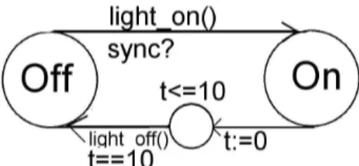
To further exemplify the different steps in the method, a small example with a lamp-switch will be viewed here. Concepts are used in this section that will be described later in this project, this example is only a short overview of the developed method to increase the understanding of the different method steps described in following sections. A detailed description of the method is presented after this initial example. The lamp switch in this example specification is turned on by pushing a button, as the light has been on for 10 time units, it is turned off automatically. Process lamp_button() (viewed in Figure 8) is simulating the environment, and timed-automaton lamp_switch() (viewed in Figure 7) is modelling the system that turns on and off the lamp. Lamp_button is synchronising with lamp_switch as the button is pushed. (The synchronisation is performed through the channel sync. The question mark and the exclamation mark after “sync” denote that this is a transition that
lamp_button and lamp_switch must perform at the same time.)
1 Specify the system
To be able to derive rules from the specification, the environment must be specified so that the events raised by the environment can be modelled. In this example, the environment is considered to be a button that is pressed or unpressed.
The system can be specified using only the automaton lamp with a guard constraining that the button must be pushed for a transition to occur. However, the proposed method for deriving rules requires that all events occurring in the system is specified as states in an automaton. The behaviour of a timed-automaton, and an ECA-rule, is different, since an automaton is waiting in its state for its guard to become true, but if a condition is false as a rule is triggered in a ARTDB, the event triggering the rule is consumed, and the rule will not be executed.
As the lamp_switch in Figure 7is in location Off, the timed-automaton is waiting to synchronize with the automaton lamp_button as the button is released. As the automata can synchronise, the light is turned on, and the automaton is entering its location On. To simulate the time, next transition is resetting the clock variable t, and the automaton is entering a state with the invariant t<=10. This forces the automaton to enter next transition exactly as t is equal to 10, which is the guard on next transition. The action of this transition is turning off the light, and the automaton enters location Off.
Figure 8: Timed-automaton Lamp_button
As the automaton Lamp_button Figure 8 is in location Up, the guard clock ==
random is simulating that somebody is pressing the lamp button at an arbitrary time.
The lamp_button is synchronizing with the lamp_switch (sync!) as the button is released.
Step 2 Verify the specification
In this step, the specification is verified to fulfil desired properties. The desired properties for this lamp switch might be that it will never deadlock, it will not get stuck in an uncontrolled loop where the light is turning on, and off by itself etc. (This automaton is of course turning on, and off by itself, since we are modelling the event of somebody pressing the button.) This step is important since it will prevent errors from propagate into the rule set.
Step 3 Derive ECA-rules
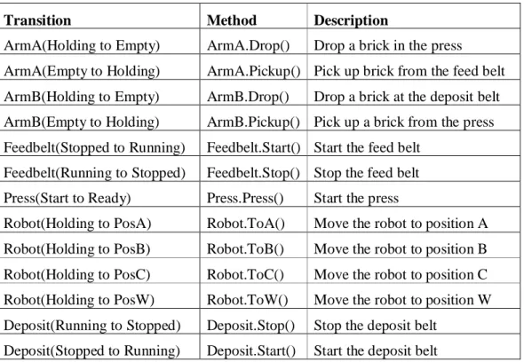
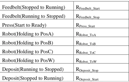
In this step, ECA-rules are derived from the model by identifying external locations, and external transitions, which are mapped into ECA-rules. In this model, the external transitions are the transitions between on and off. These transitions are translated into the method calls Light.TurnOff() and Light.TurnOn().
The events for this example specification is defined as event ELight_becomOn is after Light.TurnOn ()
event ETurn_off is after ELight_becomOn[tocc(ELight_becomOn+10)]
event EButton_becomeDown is abstract
The composite events that are triggering the rule that are turning on the light are a sequence of the event of turning off the light, and pushing the button.
event ETurn_on is ELight_becomeOff; EButton_becomeDown
The rules derived are Turn_on_light and Turn_off_light. They are preserving the models behaviour by turning on, and off the lights as events have occurred.
rule Turn_on_light on ETurn_on
do begin
Light.TurnOn() end
ECA rule 1: Turn_on_light
rule Turn_off_light on ETurn_off
do begin
Light.TurnOff() end
ECA rule 2:Turn_off_light
Step 4 Verify the rules with respect to the model
The modelled systems behaviour must be preserved during the transformation into rules. In this project, the behaviour is assumed to be preserved if the pre- and post- conditions of the transitions in the timed-automaton model are equal to the pre- and post- conditions of the transitions corresponding ECA-rules. Each rule is assumed to be performed in one transaction, this implies that the rule is performed in isolation, and no other rules may interfere with the executing rule. There may not exist any ECA-rule in the derived rule set that has no corresponding transition in the timed-automaton. In the example specification, the pre condition for the lamp to be turned on is that it is turned off, and that the button is down. This pre condition must also be verified to be true for the rule Turn_on_light.
5.2
Detailed description of extracted method
This section is a detailed description of the method extracted for deriving a predictable ECA-rule set from timed-automaton specifications.
5.2.1 Specify the application
The specification of the application may be performed in very different ways, and the resulting models may be very different, even though they have the same invariant and reachability properties.
We assume, that a good timed-automata specification for deriving ECA-rules will follow the same criteria as any good software design in the matter of dividing the system into modules, where each module has a well defined task, and where the coupling between the modules are low. An important step to achieve this modularisation is the organisation of the rules. The set of ECA-rules derived from the timed-automaton model will contain the same information as the timed-automaton. Additional code, e.g. for hardware interactions, is not addressed in this project.
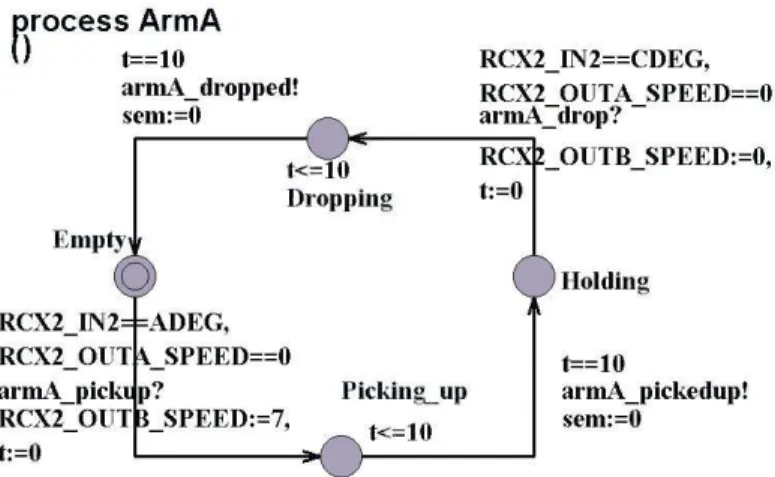
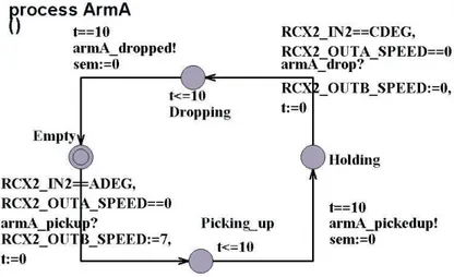
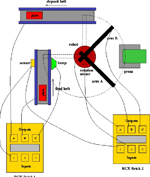
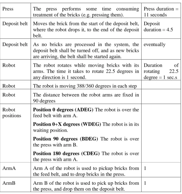
To be able to organize the rules, it is convenient to group sets of rules into different rule classes. For this approach to be feasible, there must be some criterion for why rules are grouped together, and why they should be considered to be a set of rules. To simplify the modelling, it is convenient to group rules which operate at the same object in the environment in the same class, e.g. to group the rules of dropping and picking up bricks with the same robot arm to one class (specified in an automaton of their own). It is not possible to drop, and pick up something at the same time, with the same arm, and it is not possible to drop something if the arm has not picked something up first, so this is a natural way of grouping rules to easily avoid unnecessary synchronisation problems in the model.
Another way of structuring rules would be to group them after their triggering events, e.g. all rules that are triggered by an insert to a particular relation are grouped together (Simon & Kotz-Dittrich, 1995, p. 648). One reason for grouping rules this way is that this is usually how rules are organized in the final implementation. However, this is not desirable if a set of rules triggered by different events is belonging to the same integrity constraint. For example, if the set of rules belonging to the press in our study are triggered by different events, a change in the press must identify, and update all rules belonging to the press. This is easier with the previous approach, and hence, rules in our study will be grouped after which object they are affecting.
Grouping rules by objects makes it easier to identify the set of rules depending on a possible future change in the environment, e.g. if some extra behaviour will be added to the press, the rules affected by the press is grouped in the same automaton. Since the system will be integrated in an environment, objects in the environment affecting the system (e.g. bricks triggering sensors which are triggering rules) will also be modelled.
To be able to use the method proposed in this project, events that are triggered by the environment must also be modelled. The behaviour of a timed-automaton is that if a guard necessary to enter a transition and leave its current state is false, the automaton is waiting in the current state until the guard becomes true, and then the transition is entered. This behaviour is not well mapped to an ECA-rule. If the entering of the current state is defined as an event, the rule is not waiting for the condition to be true, if the condition is false, the event is consumed, and nothing will happen as the condition eventually becomes true. Hence, the desire to use event composition, and reduce the number of conditions to be evaluated implies that all events must be modelled as locations, and not as conditions. External applications, or objects out of control of the active database, and not expected to be covered by the final rule-set, will be modelled in separate automata. To verify that all events are specified as locations, there may not be any conditions in the model that is depending on any prior event. However, in some cases it might be necessary to use the condition part of a rule, e.g. if one event is triggering more than one rule, the condition part can determine which one of the rules that will be triggered.
5.2.2 Verify the specification
The use of Uppaal makes it possible to verify the correctness of the timed-automaton specification with respect to invariant and reachability properties. The importance of the correctness of different properties depends on the application. We intend to use this method on real-time applications with real-time requirements. As described in earlier sections we have identified the absence of cascade cycles, absence of action and condition race, the ability to limit the depth of cascade triggering, and the ability
to fulfil the timeliness requirements to be the most important properties to realize in the forthcoming set of rules. These requirements must therefore hold in the timed-automaton specification.
The verifier in Uppaal can automatically discover properties like absence of deadlock, and the ability to fulfil the timeliness requirements in the model. However, cascade cycles, and the ability to limit the depth of cascade triggering must be checked with the simulator as the tool has no knowledge of the forthcoming rule set.
Since the entire behaviour of the system is intended to be specified in ECA-rules, almost all rules will trigger another rule. Cascade triggering is desirable in this case, but it must not be out of control. The depth of cascade triggering must be defined. To prevent cascade cycles from appearing in the resulting set of rules, it is important that no cycles in the model are derived into rules in an uncontrolled way.
Action race occurs when two or more simultaneously fired rules write to the same set of data, and condition race occurs when an action race concerns data read by conditions of other rules. The absence of action race implies absence of condition race. These properties must be evaluated, but it will be done after the rules are derived, since the set of rules must be known.
5.2.3 Derive ECA-rules from the specification
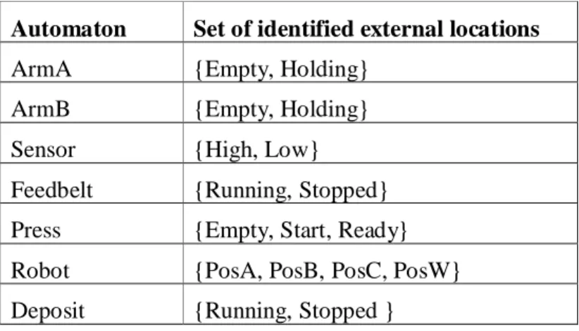
Each automaton is composed by external and internal locations (local states (locations) of that automaton). As the system model reaches a particular global state, the locations of all automata are considered. The set of external locations of an automaton are in this project defined as the finite acceptance states of that particular automaton. For example, in the Deposit automaton in Figure 9, Stopped and Running are defined to be external locations, and finite acceptance states for that automaton. An external transition represents a behaviour that can be identified in the requirement specification. The Deposit automaton is modelling a deposit belt used for transporting a brick in the system. Locations that are not defined as external are named internal; these are “help locations” used for e.g. time simulation or, as in Figure 9, Waiting is an internal location, since it is a “help location” for another automaton. An internal location is not visible outside the system, the fact that the automaton is in Waiting in this particular automaton is not visible since the visible states of the deposit belt is if the belt is running or stopped.
Figure 9: Timed-automaton Deposit
The overall approach used for the condition, and action part is to map the guard in the transition to the condition part of the rule, and the transitions assignment part to the
action part of the rule. The action and conditions for the transition from Running to Stopped in Figure 9 would then be:
Condition: nr_of_bricks ==0
Action: RCX1_OUTA_SPEED:=0
However, the translation of a guard into a condition is avoided in this project, since a rule does not wait for a condition to be true as its event has occurred. Because of this divergence between rules and timed-automata specifications, the timed-automaton specification is performed with a minimum set of guards, and these are translated into conditions only if the behaviour can be preserved by the derived rule. Another important step towards a method for the derivation of ECA-rules is to determine what is considered to be an event in the system, and how an event should be specified. There is previous work on specifying events with finite automata (Gehani, et al., 1992). The benefit of specifying events in an automaton is that composite events may be detected on the fly, through an acceptance state of the automaton. This principle of specifying an event will be evaluated in the context of this project. As an automaton enters a location, specified as an event acceptance state, the event is considered to occur. Hence, the entering of the external location is considered to be the event part of the ECA-rule. The approach for composite event detection will however differ from the approach taken in (Gehani, et al., 1992), since the entering of an external location in an automaton will be considered as a primitive event. Composite events are considered to be events triggered by the occurrence of several primitive events, e.g. the composite event E3 is triggered as the primitive events E1 and E2 has occurred (automaton1 and automaton2 have entered their acceptance states).