Modelling of long term geochemical evolution
and study of mechanical perturbation of
bentonite buffer of a
KBS-3
repository
François Marsal, Laurent de Windt, Delphine Pellegrini,
Frédéric Deleruyelle and Christophe Serres
SSI Rapport
2008:07
Rapport från Statens strålskyddsinstitut
tillgänglig i sin helhet via www.ssi.se
SKI Rapport 2008:24
Ultraviolet, solar and optical radiation
Ultraviolet radiation from the sun and solariums can result in both long-term and short-term effects. Other types of optical radiation, primarily from lasers, can also be hazardous. SSI provides guidance and information.
Solariums
The risk of tanning in a solarium are probably the same as tanning in natural sunlight. Therefore SSI’s regulations also provide advice for people tanning in solariums.
Radon
The largest contribution to the total radiation dose to the Swedish population comes from indoor air. SSI works with risk assessments, measurement techniques and advises other authorities.
Health care
The second largest contribution to the total radiation dose to the Swedish population comes from health care. SSI is working to reduce the radiation dose to employees and patients through its regulations and its inspection activities.
Radiation in industry and research
According to the Radiation Protection Act, a licence is required to conduct activities involving ionising radiation. SSI promulgates regulations and checks compliance with these regulations, conducts inspections and investigations and can stop hazardous activities. Nuclear power
SSI requires that nuclear power plants should have adequate radiation protection for the generalpublic, employees and the environment. SSI also checks compliance with these requirements on a continuous basis.
Waste
SSI works to ensure that all radioactive waste is managed in a manner that is safe from the standpoint of radiation protection.
Mobile telephony
Mobile telephones and base stations emit electromagnetic fields. SSI is monitoring developments and research in mobile telephony and associated health risks.
Transport
SSI is involved in work in Sweden and abroad to ensure the safe transportation of radioactive substances used in the health care sector, industrial radiation sources and spent nuclear fuel.
Environment
“A safe radiation environment” is one of the 15 environmental quality objectives that the Swedish parliament has decided must be met in order to achieve an ecologically sustainable development in society. SSI is responsible for ensuring that this objective is reached.
Biofuel
Biofuel from trees, which contains, for example from the Chernobyl accident, is an issue where SSI is currently conducting research and formulating regulations.
Cosmic radiation
Airline flight crews can be exposed to high levels of cosmic radiation. SSI participates in joint international projects to identify the occupational exposure within this job category.
Electromagnetic fields
SSI is working on the risks associated with electromagnetic fields and adopts countermea-sures when risks are identified.
Emergency preparedness
SSI maintains a round-the-clock emergency response organisation to protect people and the environment from the consequences of nuclear accidents and other radiation-related accidents.
SSI Education
is charged with providing a wide range of education in the field of radiation protection. Its courses are financed by students' fees.
SSI rapport: 2008:07 mars 2008
ISSn 0282-4434
The conclusions and
viewpoints presented
in the report are
those of the authors
and do not necessarily
coincide with those
of the SSI.
Författarna svarar
själva för innehållet
i rapporten.
edItorS / redaktörer
: François Marsal
1), Laurent de Windt
2),
Delphine Pellegrini
1), Frédéric Deleruyelle
1)and Christophe Serres
1) 1) French Institute for Radiological Protection and Nuclear Safety (IRSN)2) Paris School of Mines (ENSMP)
tItle / tItel
:
Modelling of long term geochemical evolution and study of
me-chanical perturbation of bentonite buffer of a KBS-3 repository / Modellering av
långsiktigt geokemisk utveckling samt studie av mekanisk störning i
bentonitbuf-fert i ett KBS-3 slutförvar.
department / avdelnIng
: Department of Nuclear Facilities and Waste
Manage-ment / Avdelningen för kärnteknik och avfall
Summary
:
PART I: The Swedish Nuclear Fuel and Waste Management Co. (SKB) has recently com-pleted a safety assessment project named SR-Can, related to the KBS-3 disposal concept. In this concept, the waste packages are surrounded by a buffer made of either MX-80 or Deponit CA-N bentonite. Interactions between the buffer and groundwater may modify the buffer composition and thus its containment proper-ties. The Swedish Radiation Protection Authorities (SSI) requested the French Institute for Radiological Protection and Nuclear Safety (IRSN) to perform the present study in support of SSI review of the SR-Can report. The purpose is to assess the geochemical evolution of both potential buffer materials due to the intrusion of different types of groundwater, with a similar modelling layout to that reported in SR-Can and detailed in Arcos et al. (2006). Three main categories of water inflows via a fracture intersecting a deposi-tion hole are considered: the Forsmark reference groundwater, a high-salinity groundwater to account for up-rise of deep-seated brines and a diluted water representing ice-melting derived-groundwater. In addition to this, the redox buffering capacity of Deponit CA-N bentonite and the thermal effect on MX-80 bentonite geochemistry have been assessed. This modelling work has been performed using the reactive transport modelling code HYTEC.The main outcome of the present study is that the intrusion of the considered groundwaters should not affect drastically the geochemistry of neither the Deponit CA-N nor the MX-80 bentonite on the long-term (100,000 y). Bentonite pH may reach high values (up to 10.5) in some cases but does not reach SKB criterion value related to bentonite chemical stability. Dissolution-precipitation of accessory minerals is not significant enough to induce important porosity changes (rise by maximum 2 %). Globally, the montmo-rillonite exchanger undergoes Na by Ca partial replacement, which may decrease the swelling pressure of the bentonite. The simulated intrusion of oxidizing waters lead to a limited perturbation, i.e. localized within bentonite near the fracture plane level. Actually, the calculated evolutions are relatively slow, so that in some cases the buffer remains in a transient stage over the whole simulation period and thus could turn hetero-geneous in geochemical properties. Regarding the effect of temperature, a heterohetero-geneous evolution is again observed, with moderate to slight dissolution-precipitation reactions either on the inner or outer border of the buffer (warmer and cooler zones) depending on the accessory minerals. These main trends in bentonite geochemical evolutions are in good agreement with the results presented in SR-Can and in Arcos et al. (2006), though some discrepancies have been pointed out, that can be explained by differences in modelling input data (mainly regarding log K values). Finally, issues in terms of processes and data would worth being further investigated as they might have a significant influence on bentonite evolutions, such as the thermo-hydraulic coupling of processes during the initial transient phase or the stability of montmorillonite. PART II: Elements of the SR-Can project relative to piping and erosion phenomena of bentonite compo-nents of a KBS-3 repository are analysed with regard to the experience feedback available at IRSN and con-sisting in experimental results obtained on samples at the UJF-Grenoble between 2000 and 2004. A synthe-sis of these tests is presented, with a closer attention to the Argillite/Bentonite tests during which phenomena of erosion occurred. The reference evolution of a KBS-3 repository, the resaturation and swelling kinetics of backfills and buffers and the possibility for a buffer to swell upwards the backfill have been considered. According to the reviewed documents, IRSN notes that the SR-Can project tackles the piping and erosion phenomena with local modellings and “rough estimates”, the latter being based on 3 “key” parameters: the water inflow in an underground opening, the concentration of bentonite in pipe water and the duration of the phenomena. IRSN considers that the reviewed elements do not evidence enough the conservatism of the parameters value, especially for the duration of the phenomena. Additional experimental results, at small and large scale, may be necessary.
SammanfattnIng: DEL I: Svensk Kärnbränslehantering AB (SKB) har nyligen genomfört en
säk-erhetsanalys, SR-Can, som baseras på KBS-3 metoden. Viktiga komponenter utgörs av kopparkapslar som omges av en buffert som består av kompakterad lera (antigen MX-80 bentonit eller Deponit CA-N bentonit). Växelverkan mellan bufferten och grundvattnet kan modifiera buffertens kemiska sammansät-tning och påverka dess isoleringsförmåga. På SSI:s och SKI:s begäran har IRSN (Institut de Radioprotec-tion et de Sûreté Nucléaire) utfört denna studie som ett stöd för myndigheternas granskning av SR-Can. Syftet är att utvärdera den geokemiska utveckling av bufferten som orsakas av inträngande grundvatten med olika kemiska sammansättningar. Modellkonceptet som används i denna studie är likartad den metod som används i SKB:s motsvarande modellering (Arcos et al., 2006). Tre typer av grundvatten har beaktats: ett referensgrundvatten från Forsmark; ett saltvatten som representerar uppströmmande djupt belägna grundvattnen, samt ett utspätt grundvattnen som bildas från glaciala smältvatten. Dessutom har redoxbuffringskapacitet i Deponit CA-N bentonit samt termisk inverkan på MX-80 utvärderats. Denna modellering har utförts med hjälp av den numeriska koden HYTEC.
Huvudslutsatsen är att inträngningen av olika typer av grundvatten inte ens på lång sikt (upp till 100 000 år) kommer att väsentligt påverka buffertens geokemiska egenskaper för vare sig MX-80 bentonit eller Deponit CA-N bentonit. Bentonitens pH kan möjligen i vissa fall öka väsentligt (upp till pH 10,5) men pH förblir ändå lägre än SKB:s gränsvärde för buffertens kemiska stabilitet. Upplösning/utfällning av acces-soriska mineral är inte tillräckligt omfattande för att åstadkomma betydelsefull porositetsförändring i buff-erten (porositeten ökar maximalt med 2 %). Modelleringsresultaten visar att det pågår en jonbytesprocess på montmorillonit mineralens yta då Na utbyts med Ca. Detta kan möjligen minska bentonitens svälltryck. Numerisk simulering av inträngningen av oxiderande grundvatten leder till en begränsad störning i ben-toniten nära inflödespunkten för en korsande sprickan. Den beräknade kemiska utvecklingen är i detta fall relativt långsam. För vissa egenskaper är bufferten fortfarande i ett transient skede genom hela simulering-sperioden och heterogenitet i buffertens geokemiska egenskaper kan då förekomma. Temperaturens påver-kan leder också till heterogen utveckling med måttlig eller obetydlig upplösning/utfällning av accessoriska mineral på både in- och utsidan av bufferten (varmare och kallare zoner). Dessa huvudsakliga tendenser för den geokemiska utvecklingen överensstämmer med SKB:s resultat (Arcos et al., 2006). Vissa avvikelser före-kommer dock som kan förklaras med att andra termodynamiska indata (huvudsakligen log K) har använts i den föreliggande studien. Slutligen påpekas att mera studier behövs för att utvärdera betydelsen av indata och den exakta formuleringen av processerna i modelleringen. De har stor inverkan på bentonitens utveck-ling såsom den kopplade termisk-hydrauliska utveckutveck-lingen i det initiala transienta skedet och stabiliteten för montmorillonit.
DEL II: Fenomenet piping/erosion som redovisas i SKB:s SR-Can projekt har analyserats med hjälp av tidi-gare erfarenheter från IRSN:s experimentella försök mellan 2000 och 2004 på Université Joseph Fourier i Grenoble (UJG). En sammanfattning av försöken presenteras med fokus på de försök där erosion av argillit/ bentonit har förekommit. Referensutvecklingen för ett KBS-3 förvar, återmättnad och svällningskinetik för buffert/återfyllning samt förekomsten av en uppåtgående svällning i bufferten har beaktats. Genom granskn-ing av de dokument som granskn-ingår i SR-Can redovisngranskn-ingen noterar IRSN att SKB har hanterat pipgranskn-ing/erosionen med lokala modeller och ”grov uppskattning”. Det sistnämnda angreppssättet är baserat på 3 nyckelpara-metrar: vatteninflödet in i en öppen förvarsanläggning innan förslutning, koncentrationen av bentonitpar-tiklar i grundvatten vid kanalbildning, samt varaktigheten av fenomenet. IRSN anser att det resonemanget i SR-Can inte ger tillräckligt stöd för de konservativa parametervärdena som valts i SR-Can, särskilt när det gäller varaktigheten av piping/erosion. Ytterligare experimentella försök I både liten och stor skala behöver genomföras.
1
Foreword
The work presented in this report is part of the Swedish Nuclear Power Inspectorate’s
(SKI) and the Swedish Radiation Protection Authority’s (SSI) SR-Can review project.
The Swedish Nuclear Fuel and Waste Management Co (SKB) plans to submit a
license application for the construction of a repository for spent nuclear fuel in
Sweden 2010. In support of this application SKB will present a safety report, SR-Site,
on the repository’s long-term safety and radiological consequences. As a preparation
for SR-Site, SKB published the preliminary safety assessment SR-Can in November
2006. The purposes were to document a first evaluation of long-term safety for the
two candidate sites at Forsmark and Laxemar and to provide feedback to SKB’s
future programme of work.
An important objective of the authorities’ review of SR-Can is to provide guidance to
SKB on the complete safety reporting for the license application. The authorities have
engaged external experts for independent modelling, analysis and review, with the
aim to provide a range of expert opinions related to the sufficiency and
appropriateness of various aspects of SR-Can. This report is one of those external
experts’ review reports, compiled by consultants at the French Institute for
Radiological Protection and Nuclear Safety (IRSN). The report consists of two parts:
Part I presents modelling of the long-term geochemical evolution of the bentonite
buffer independent of SKB’s approach. In Part II issues of mechanical perturbation
such as piping/erosion have been reviewed.
The conclusions and judgements in this report are those of the authors and may not
necessarily coincide with those of SKI and SSI. The authorities own review will be
published separately (SKI Report 2008:23, SSI Report 2008:04 E).
2
Förord
Denna rapport är en underlagsrapport till Statens kärnkraftinspektions (SKI) och
Statens strålskyddsinstituts (SSI) gemensamma granskning av Svensk
Kärnbränslehantering AB:s (SKB) säkerhetsredovisning SR-Can.
SKB planerar att lämna in en ansökan om uppförande av ett slutförvar för använt
kärnbränsle i Sverige under 2010. Som underlag till ansökan kommer SKB presentera
en säkerhetsrapport, SR-Site, som redovisar slutförvarets långsiktiga säkerhet och
radiologiska konsekvenser. Som en förberedelse inför SR-Site publicerade SKB den
preliminära säkerhetsanalysen SR-Can i november 2006. Syftena med SR-Can är bl.a.
att redovisa en första bedömning av den långsiktiga säkerheten för ett KBS-3-förvar
vid SKB:s två kandidatplatser Laxemar och Forsmark och att ge återkoppling till
SKB:s fortsatta arbete.
Myndigheternas granskning av SR-Can syftar till att ge SKB vägledning om
förväntningarna på säkerhetsredovisningen inför den planerade tillståndsansökan.
Myndigheterna har i sin granskning tagit hjälp av externa experter för oberoende
modellering, analys och granskning. Denna rapport är en del av den externa
expertgranskningen. Rapporten har skrivits av experter på Institut de Radioprotection
et de Sûreté Nucléaire (IRSN) i Frankrike. Det finns två delar i rapporten. Del I
redovisar oberoende modellering av den långsiktiga geokemiska utvecklingen av
bufferten i slutförvaret. I del II granskas SKB:s redovisning i SR-Can av mekaniska
processer såsom kanalbildning (piping/erosion) i bufferten.
Slutsatserna i denna rapport är författarnas egna och överensstämmer inte
nödvändigtvis med SKI:s eller SSI:s ställningstaganden. Myndigheternas egen
granskning publiceras i en annan rapport (SKI Rapport 2008:19; SSI Rapport
2008:04).
ABSTRACT
The Swedish Nuclear Fuel and Waste Management Co. (SKB) has recently completed a safety assessment project named SR-Can, related to the KBS-3 disposal concept. In this concept, the waste packages are surrounded by a buffer made of either MX-80 or Deponit CA-N bentonite. Interactions between the buffer and groundwater may modify the buffer composition and thus its containment properties. The Swedish Radiation Protection Authorities (SSI) requested the French Institute for Radiological Protection and Nuclear Safety (IRSN) to perform the present study in support of SSI review of the SR-Can report. The purpose is to assess the geochemical evolution of both potential buffer materials due to the intrusion of different types of groundwater, with a similar modelling layout to that reported in SR-Can and detailed in Arcos et al. (2006). Three main categories of water inflows via a fracture intersecting a deposition hole are considered: the Forsmark reference groundwater, a high-salinity groundwater to account for up-rise of deep-seated brines and a diluted water representing ice-melting derived-groundwater. In addition to this, the redox buffering capacity of Deponit CA-N bentonite and the thermal effect on MX-80 bentonite geochemistry have been assessed. This modelling work has been performed using the reactive transport modelling code HYTEC.
The main outcome of the present study is that the intrusion of the considered groundwaters should not affect drastically the geochemistry of neither the Deponit CA-N nor the MX-80 bentonite on the long-term (100,000 y). Bentonite pH may reach high values (up to 10.5) in some cases but does not reach SKB criterion value related to bentonite chemical stability. Dissolution-precipitation of accessory minerals is not significant enough to induce important porosity changes (rise by maximum 2 %). Globally, the montmorillonite exchanger undergoes Na by Ca partial replacement, which may decrease the swelling pressure of the bentonite. The simulated intrusion of oxidizing waters lead to a limited perturbation, i.e. localized within bentonite near the fracture plane level. Actually, the calculated evolutions are relatively slow, so that in some cases the buffer remains in a transient stage over the whole simulation period and thus could turn heterogeneous in geochemical properties. Regarding the effect of temperature, a heterogeneous evolution is again observed, with moderate to slight dissolution-precipitation reactions either on the inner or outer border of the buffer (warmer and cooler zones) depending on the accessory minerals. These main trends in bentonite geochemical evolutions are in good agreement with the results presented in SR-Can and in Arcos et al. (2006), though some discrepancies have been pointed out, that can be explained by differences in modelling input data (mainly regarding log K values). Finally, issues in terms of processes and data would worth being further investigated as they might have a significant influence on bentonite evolutions, such as the thermo-hydraulic coupling of processes during the initial transient phase or the stability of montmorillonite.
TABLE OF CONTENTS
ABSTRACT ... 1
LIST OF FIGURES ... 4
LIST OF TABLES ... 6
1 INTRODUCTION ... 7
2 MODELLING FEATURES ... 9
2.1 REACTIVE TRANSPORT CODE HYTEC... 9
2.1.1 Main concepts and equations... 9
2.1.2 Discretization and coupling schemes... 9
2.1.3 Kinetics of geochemical processes ...10
2.1.4 Cation exchange and surface complexation ...10
2.2 THERMODYNAMIC AND KINETIC DATA ...12
2.2.1 Aqueous chemistry and dissolution/precipitation reactions...12
2.2.2 Cation exchange and surface complexation ...13
2.3 GEOMETRICAL DESIGN: KBS-3 CONCEPT AND SIMULATION GRIDS ...14
2.4 GEOCHEMISTRY AND MINERALOGY...15
2.4.1 Groundwaters ...15
2.4.2 Deponit CA-N bentonite ...17
2.4.3 MX-80 bentonite ...18
2.4.4 Waste package and host rock...18
2.5 FLOW AND SOLUTE TRANSPORT PARAMETERS ...21
2.5.1 Bentonites and fracture ...21
3 DEPONIT CA-N BENTONITE/GROUNDWATER LONG-TERM INTERACTIONS ... 22
3.1 REFERENCE CASE, THE FORSMARK GROUNDWATER ...22
3.2 HIGH-SALINITY WATER INTRUSION, THE LAXEMAR GROUNDWATER ...29
3.3 ICE-MELTING WATER INTRUSION, THE GRIMSEL GROUNDWATER ...35
3.4 SENSITIVITY ANALYSIS ...38
3.4.1 Gypsum equilibrium constants ...38
3.4.2 Activity correction models...40
3.4.3 Numerical considerations ...40
4 MX-80 BENTONITE/GROUNDWATER LONG-TERM INTERACTIONS... 43
4.1 REFERENCE CASE, THE FORSMARK GROUNDWATER ...43
4.2 HIGH-SALINITY WATER INTRUSION, THE LAXEMAR GROUNDWATER ...48
4.3 ICE-MELTING WATER INTRUSION, THE GRIMSEL GROUNDWATER ...53
5 DURABILITY OF THE DEPONIT CA-N REDOX BUFFERING CAPACITY... 57
5.1 CONTEXT...57
5.2 INTRUSION OF ICE-MELTING WATER WITH INCREASING OXYGEN CONTENTS ...58
6 THERMAL EFFECT ON MX-80 BENTONITE... 64
7 SUMMARY AND CROSS-COMPARISON OF SIMULATED CASES... 71
8 CONCLUSION ... 74
9 REFERENCES... 76
APPENDIX... 78
LIST OF FIGURES
Figure 2-1. Simplified representation of a montmorillonite clay structure. ...11 Figure 2-2. Schematic view of the KBS-3 disposal concept (SKB, 2006) and representation of the simulated subsystem with an hypothetical fracture plane. ...16 Figure 2-3. Calculation grid representative for the cross-section at the level of the fracture plane...17 Figure 2-4. Calculation grid representative for the cylindrical geometry (rotation around the z axis, perpendicularly to the fracture plane). ...17 Figure 2-5. Advective flow (Darcy velocity) in the fracture plane; coarser grid for a better visualization of the flow field. ...21 Figure 3-1. Reference case with Deponit CA-N bentonite: evolution of pH and pe over 100,000 y...24 Figure 3-2. Reference case with Deponit CA-N bentonite: evolution of exchangeable Ca (top), Na (middle) and Mg (bottom) populations over 100,000 y. ...25 Figure 3-3. Reference case with Deponit CA-N bentonite: evolution of gypsum (top), dolomite (middle) and calcite (bottom) contents over 100,000 y. ...26 Figure 3-4. Pourbaix/pe-pH diagram of iron (Fe, HCO3 and SO4 concentrations identical to those of the initial pore water of the Deponit CA-N)...27 Figure 3-5. Reference case with Deponit CA-N bentonite: evolution of the porosity over 100,000 y...27 Figure 3-6. Reference case with Deponit CA-N bentonite: evolution of pH and pe over the first 10,000 y. ...28 Figure 3-7. Reference case with Deponit CA-N bentonite: evolution of exchangeable Na and Ca populations over the first 10,000 y. ...28 Figure 3-8. High-salinity water intrusion in Deponit CA-N bentonite: evolution of pH and pe over 100,000 y...31 Figure 3-9. High-salinity groundwater intrusion in Deponit CA-N bentonite: evolution of pyrite (top) and siderite (bottom) contents over 100,000 y. ...32 Figure 3-10. High-salinity water intrusion in Deponit CA-N bentonite: evolution of DPN-OH2+ site concentration (top) and exchangeable Ca population (bottom) over 100,000 y. ...33 Figure 3-11. High-salinity groundwater intrusion in Deponit CA-N bentonite: evolution of pore water chemistry, cation exchange population and mineralogy in the bentonite, 50 cm above the fracture level. ...34 Figure 3-12. Evolution with time of cumulative flux of carbonate, chloride and sulfate ions in the full volume of the bentonite buffer and in the zone around the canister (5 cm width). ...34 Figure 3-13. Ice-melting water intrusion in Deponit CA-N bentonite: evolution of pH and pe over 100,000 y...36 Figure 3-14. Ice-melting water intrusion in Deponit CA-N bentonite: evolution of exchangeable Ca (top) and Na (bottom) populations over 100,000 y. ...37 Figure 3-15. Ice-melting water intrusion in Deponit CA-N bentonite: evolution of calcite (top) and dolomite (bottom) over 100,000 y. ...38 Figure 3-16. Influence of the Log K value selected for gypsum on the stability of this mineral: evolution of gypsum concentration at 10,000 and 50,000 y for the reference case with Deponit CA-N Bentonite. ...39 Figure 3-17. Highly-saline groundwater intrusion, modelling results obtained with an iterative sequential coupling and an adaptative time step (left) and with a non iterative sequential coupling and a fixed time step of 1 y (right).
...41
Figure 3-18. Illustration of mass distributions for FV and FE approaches. Too much mass is defined for uncorrected FE approach. ...41 Figure 3-19. Highly-saline groundwater intrusion, the number of nodes is increased by a factor 4 between the top and bottom graphs. ...42 Figure 4-1. Reference case with MX-80 bentonite: evolution of pH and pe over 100,000 y...44 Figure 4-2. Reference case with MX-80 bentonite: evolution of exchangeable Ca (top) and Na (bottom) populations over 100,000 y. ...45 Figure 4-3. Reference case with MX-80 bentonite: evolution of exchangeable Na and Ca populations as a function of time over 100,000 y at two points, located at 0.5 and 3.9 m above the fracture level as defined in the figure on the right. ...46 Figure 4-4. Reference case with MX-80 bentonite: evolution of gypsum content over 5,000 y...46 Figure 4-5. Reference groundwater intrusion in with MX-80 bentonite with carbonate minerals: evolution of pH and calcite content over 100,000 y...47 Figure 4-6. Reference groundwater intrusion in with MX-80 bentonite with carbonate minerals: evolution of aqueous carbonate concentration (top) and pH (bottom) at two points, located at 0.5 and 3.9 m above the fracture level as defined in Figure 4-3. ...48 Figure 4-7. High-salinity water intrusion in MX-80 bentonite: evolution of pH and pe over 100,000 y...50 Figure 4-8. High-salinity water intrusion in MX-80 bentonite: evolution of exchangeable Ca (top), Na (middle) and Mg (bottom) populations over 100,000 y. ...51 Figure 4-9. High-salinity water intrusion in MX-80 bentonite with carbonate minerals: evolution of pH over 100,000 y. ...52 Figure 4-10. High-salinity water intrusion in MX-80 bentonite with carbonate minerals: evolution of calcite and siderite contents as a function of time over 100,000 y at two points, located at 0.5 m (left) and 3.9 m (right) above the fracture level as defined in Figure 4-3...52 Figure 4-11. Ice-melting water intrusion in MX-80 bentonite: evolution of pH and pe over 100,000 y...54 Figure 4-12. Ice-melting water intrusion in MX-80 bentonite: evolution of exchangeable Ca (top), Na (bottom) populations over 100,000 y. ...55 Figure 4-13. Ice-melting water intrusion in MX-80 bentonite with carbonate minerals: evolution of pH (top), calcite content (middle) and exchangeable Ca (bottom) over 100,000 y. ...56 Figure 5-1. Titration of a siderite/pyrite buffer by dissolved oxygen assuming thermodynamic equilibrium (left); kinetic rate of oxygen consumption by siderite and pyrite according to pH and oxygen fugacity (right)...58 Figure 5-2. Ice-melting groundwater intrusion in Deponit CA-N bentonite (fug O2 = 0.04), evolution of pH (top), pe and the dissolved oxygen content over 90,000 y. ...60 Figure 5-3. Ice-melting groundwater intrusion in Deponit CA-N bentonite (fug O2 = 0.04), cross-section through the bentonite buffer showing the interdependency between the redox state (pe) and the redox-poising minerals. ....61 Figure 5-4. Ice-melting groundwater intrusion in Deponit CA-N bentonite (fug O2 = 0.04), progressive dissolution of pyrite and siderite yielding precipitation of secondary ferrihydrite (at 90,000 y)...61 Figure 5-5. Ice-melting groundwater intrusion in Deponit CA-N bentonite (fug O2 = 0.04), pyrite, siderite and secondary iron-mineral contents calculated at 90,000 y considering either ferrihydrite (top) or goethite precipitation. ...62 Figure 5-6. Ice-melting groundwater intrusion in Deponit CA-N bentonite, extension of the pyrite dissolution front at 90,000 y as a function of the oxygen fugacity...63
Figure 6-1. Thermal evolution of the near field (Arcos et al., 2006). ...64
Figure 6-2. Constant temperature field modelled over 1,000 y. The temperature of the bentonite inner border is set at 80°C while that at its outer border is set at 65°C. ...65
Figure 6-3. Thermal effect on MX-80 bentonite without initial carbonate minerals: evolution of pH and aqueous carbonate contents over 1,000 y. ...67
Figure 6-4. Thermal effect on MX-80 bentonite without initial carbonate minerals: evolution of exchangeable Ca (top) and Na (bottom) populations over 1,000 y. ...68
Figure 6-5. Thermal effect on MX-80 bentonite without initial carbonate minerals: evolution of dolomite (top), anhydrite (middle) and quartz (bottom) contents over 1,000 y. Note that for a better observation, scale bars have been limited to a very narrow range...69
Figure 6-6. Thermal effect on MX-80 bentonite with carbonate minerals in its initial composition: evolution of siderite (top) and pyrrhotite (bottom) contents over 1,000 y. ...70
LIST OF TABLES
Table 2-1. Cation exchange and surface complexation data. ...14Table 2-2. Chemical composition of the groundwaters and bentonite pore waters. ...19
Table 2-3. Saturation indices calculated for groundwaters and bentonite pore waters. ...20
Table 2-4. Flow and transport parameters selected for bentonite and fracture zones. ...21
Table 3-1. Gypsum formation constant (Ca2+ + SO 42- + H20 → CaSO4.H20) from various thermodynamic databases..39
Table 6-1. Chemical composition of MX-80 bentonite pore water at 80°C and 15°C. ...65
1 INTRODUCTION
The Swedish Nuclear Fuel and Waste Management Co. (SKB) has recently completed a safety assessment project named SR-Can, as a preparatory stage for the next assessment SR-Site that will be used in support of SKB’s application for a final deep underground disposal of high-level long-lived radioactive waste. The Swedish Radiation Protection Authorities (SSI), which reviews the SR-Can report, requested the French Institute for Radiological Protection and Nuclear Safety (IRSN) to perform independent study and technical appraisal on some geochemical and mechanical aspects of the SR-Can report in support of SSI review process. The present document focuses on geochemical issues, as described hereafter. A second document (IRSN, DSU/SSIAD n°2) is issued on mechanical concerns.
The safety assessment project SR-Can (SKB, 2006) relates to the KBS-3 disposal concept, in which copper canisters containing spent nuclear fuel are emplaced in a granitic rock at a depth of approximately 500 m, in vertical holes equipped with a surrounding engineered component made of bentonite clay. The primary safety function of the KBS-3 concept is to completely isolate the waste and should isolation be breached, the secondary safety function is to retard a potential release from the repository. The bentonite buffer contributes to these main safety functions of isolation and retardation through subordinate functions, among which:
− to prevent advective transport in the deposition hole, so as to limit the inflow of dissolved copper corroding agents to the canister, thereby providing canister protection against corrosion (isolation function);
− to slow transport of potential radionuclide releases from the canister, by avoiding advection, providing sorption and ensuring that radionuclide release will be limited by their solubility (retardation function).
Another important issue related to the buffer is to preserve reducing conditions so as to provide a chemical environment favourable to low canister corrosion rates, to a stable fuel matrix and to low radionuclide solubility. Interactions between the buffer and groundwater may modify the buffer composition and thus its chemical and hydraulic containment properties. The evaluation of the potential geochemical evolutions due to such interactions is therefore required for safety assessment purpose. Arcos et al. (2006) developed a numerical model with this aim, which addresses the influence on near-field geochemistry of the intrusion of various types of water for a range of conditions and assumptions, using the reactive transport code PHAST.
In the frame of the SR-Can review, SSI requested IRSN to perform a geochemical modelling of the buffer evolution with the same or similar layout to that presented in Arcos et al. (2006), completed with a specific point related to the handling of ion exchange reactions with solute transport and the assessment of the durability of the reducing capacity of the buffer.
The present work thus addresses the geochemical perturbations due to the intrusion of waters into the bentonite buffer, via a fracture in the Host-rock intersecting a deposition hole, on the basis of reactive transport modelling using the code HYTEC. In the following, the section 2 is devoted to the presentation of the modelling features
(code HYTEC, thermodynamic and kinetic data, geometrical design, geochemical and hydraulic parameters). Simulations results are reported in next sections, in terms of calculated changes in geochemical master-characteristics which control the chemical and hydraulic containment properties of the bentonite, namely pH and pe (stability of bentonite and radionuclide solubility), exchanged ion populations and mineralogy (hydraulic properties related to swelling pressure and porosity). A particular attention is given to the processes that control the evolution of these characteristics. When appropriate, the variations in concentration of aqueous species in bentonite pore water are also commented, in a first attempt, especially with regards to corrosion. More precisely, section 3 documents the simulations performed considering the interaction of Deponit CA-N bentonite with three categories of inflowing waters, i.e. the Forsmark reference groundwater, a high-salinity groundwater to account for up-rise of deep-seated brines and diluted water for ice-melting derived-groundwater. This section also describes some sensitivity analysis calculations to modelling features. Section 4 presents the same kind of simulations but with a different buffer, i.e. MX-80 bentonite. The redox buffering capacity of Deponit CA-N bentonite is assessed in section 5, whereas section 6 focuses on the influence of the transient thermal phase in the case where MX-80 bentonite interacts with the reference groundwater. A summary of the whole sets of calculation results is given in section 7 together with a cross-comparison, between the simulation cases treated in the present study on the one hand and with respect to the outcomes from Arcos et al. (2006) on the other hand. At last, the main outlines of each simulation case are recapitulated as a summarizing table in an appendix.
2 MODELLING FEATURES
2.1 REACTIVE TRANSPORT CODE HYTEC
2.1.1 MAIN CONCEPTS AND EQUATIONS
HYTEC (van der Lee et al. (2003); van der Lee (2005)) is a reactive transport code commonly used for transport in porous media under saturated and unsaturated conditions. This numerical code simulates advective and diffusive transport of solutes coupled with chemical reactions (aqueous chemistry, dissolution/precipitation of minerals, cation exchange and surface complexation) at equilibrium or with kinetic control. Transport is coupled to chemistry according to the following equation in a saturated medium:
(
)
t
c
U
c
c
D
t
c
i i i d i∂
∂
−
−
∇
⋅
∇
=
∂
∂
ω
ω
,where the dispersive/diffusive coefficient, Dd = De + α U, De is the effective diffusion coefficient, α the
dispersivity, U the Darcy velocity, ω is the porosity. The velocity field U can be obtained from the hydraulic conductivity K and Darcy’s law. Note that the porosity is explicitly included in the equation since this entity is subject to change in time and space due to geochemical processes such as precipitation, dissolution or clogging of pores by colloidal retention. The terms ci and
c
i are respectively the mobile and immobile concentrations of aspecies per unit volume of solution. The fixed or solid fraction is evaluated on the basis of chemical calculations, whereas the aqueous fraction is a function of chemical and transport processes.
2.1.2 DISCRETIZATION AND COUPLING SCHEMES
HYTEC code solves the multi-component transport problem according to operator splitting method combined with a sequential iterative approach and a severe, normalized convergence criterion. Transport and chemistry are solved one after the other within a single time-step. Since both parts are dependent on each other, an accurate solution is obtained only after several iterations within the time-step. Different studies demonstrate the importance of iterative improvement when applying the sequential approach (see references in van der Lee et al., 2003). HYTEC recovers from diverging or slowly converging situations by reducing the current time-step. Inversely, the code increases the time-step when possible. Hence HYTEC adapts the time step to the numerical stiffness of the problem.
HYTEC is strongly coupled, e.g. hydraulic conductivity and diffusion parameters might evolve when mineral precipitation or dissolution changes the local porosity. Therefore, HYTEC allows accounting for clogging by precipitation, or to the contrary, for porosity increase by leaching of minerals (De Windt et al., 2004). This option has not been used for the present study since the porosity appeared to be almost constant throughout preliminary simulations.
Chemistry is solved by the “basis component” method according to an improved Newton-Raphson algorithm enhanced by a polishing factor to improve its global convergence capacity. The corresponding chemical module is
called JCHESS (van der Lee and De Windt, 2002). The R2D2 hydrodynamic code (Lagneau, 2003) (computing flow and advective–dispersive-diffusive transport) is coupled with JCHESS in the HYTEC platform. R2D2 is based on a finite volume (FV) approach which is particularly useful for treatment of the variable porosity problem. This code uses a flexible grid based on Thiesen polygons and hence is easily adapted to complex geometries, albeit currently limited to 2D cylindrical or Cartesian coordinates.
2.1.3 KINETICS OF GEOCHEMICAL PROCESSES
HYTEC is structured with respect to the local thermodynamic equilibrium approach but kinetics can be optionally introduced for dissolution and precipitation of solid phases, microbiology-mediated reactions and sorption/desorption processes. The following kinetic formula for a solid (mineral, colloidal) species, S, is for the present study:
where k denotes a kinetic constant in mol/m2/s; A
v is the volumetric surface area expressed in m2/m3; p is an arbitrary power-constant used to fit the law to experimental data; Q/Ks is the saturation state; ai is a factor
including reaction-catalyzing (ai>0) or inhibiting (ai<0) species and may be different for precipitation and dissolution. An example will be given below in the case of pyrite dissolution (subsections 2.2 and 5.1).
2.1.4 CATION EXCHANGE AND SURFACE COMPLEXATION
Figure 2-1 gives a simplified representation of a montmorillonite clay structure. This mineral represents the main component of bentonites (about 80 %wt of the Deponit CA-N and about 87 %wt of the MX-80 bentonite). It undergoes two distinct sorption mechanisms. Cation exchange takes place in the interlayer space to balance ionic charge disequilibrium in the clay skeleton. This exchange mechanism buffers the bentonite hydrochemistry, in particular for Ca2+ or Na+ ions. Surface complexation on the clay surface is another important process with respect to water/rock interactions: acid/base reactions take place at the clay/solution interface and control, to some extent, the pH of the bentonite pore water. HYTEC accounts simultaneously for interlayer cation exchange and surface complexation, either in thermodynamic equilibrium or kinetic paths. However, since the kinetic of sorption is much faster than mass diffusion in the case of compacted bentonite, kinetic of sorption will not be considered in this study.
Figure 2-1. Simplified representation of a montmorillonite clay structure.
2.1.4.1 Cation exchange
Any cation exchange reaction can be written in terms of a mass-action law, for instance:
where the bar stands for an ion in the interlayer space and the parenthesis for the ion activity either in the solution or in the interlayer space. HYTEC, PHAST, and most of the other reactive transport codes use this equation to simulate cation exchange reactions.
The calculation of the ion activity in the interlayer space is still a debated question. One of the simplest and most common approaches is the Gaines-Thomas formalism (Helfferich, 1995):
KGT, which is known as the “selectivity coefficient”, can be experimentally measured and easily (automatically) re-expressed as a mass-balance constant K required for the reactive transport code (see Bradbury and Baeyens, 1998). An implicit assumption in the calculations is that selectivity coefficients are constants over the ranges of considered cation occupancies. The equivalent fraction fA can be written as a function of the cation exchange capacity (CEC):
.
2.1.4.2 Surface complexation
The interruption of the crystal network at the surface of the clay pellet leads to hydroxyl groups such as silanol Si-OH and aluminol Al-Si-OH ones, which affinity depends on their location on the surface (basal or edge sites). These functional groups are generally amphoteric, that is to say they can take or give a proton to the solution:
and be characterized by two pKa values.
In addition to protons, the other cations and some anions can also react with the clay surface groups. At the overall balance of the site concentrations corresponds an electrical state of the surface and, accordingly, an electrical potential field propagating more or less within the pore volume. HYTEC uses the double layer theory, which takes into account the intrinsic acid/base and ion complexation constants.
2.2 THERMODYNAMIC AND KINETIC DATA
2.2.1 AQUEOUS CHEMISTRY AND DISSOLUTION/PRECIPITATION REACTIONS
In the present study, local thermodynamic equilibrium assumption is assumed for all the aqueous reactions including the electron transfer (redox) mechanisms. The dissolution/precipitation kinetic of carbonates (calcite, dolomite) and sulfates (gypsum) are fast (Savage et al., 2002), at least significantly faster than diffusion mass transfer and were also modelled at a local equilibrium level. The equilibrium constants (log K) come from the EQ3/6 (Wolery, 1992) thermodynamic database (TDB), version 8.6, but:
− for dolomite, the constant was taken from the Nagra TDB (Pearson and Berner, 1991), as commented in section 2.4.2. Bradbury and Baeyens (1998) also used this optional constant for dolomite in their modelling work of Opalinus Clay pore water;
− for gypsum, the constant from the EQ3/6 TDB has been identified to be lower than that contained in other TDBs. A sensitivity analysis to this parameter value has therefore been performed for one of the calculation cases treated in the present study, so as to assess the potential influence of this mineral stability (see section 3.4).
As in Arcos et al. (2006), montmorillonite dissolution is assumed in any case to be too low to be coupled to the chemical evolution of the system over the 100,000 y duration. This hypothesis is supported by the following grounds: i) montmorillonite is only slightly under-saturated in most of the chemical conditions considered in this study except for the Grimsel diluted groundwater, ii) the kinetic dissolution constant is relatively low (around 1x10-14 – 3x10-14 mol/m2/s at 25°C in a pH range of 6 to 10, see for instance Köhler et al., 2003, Read et al. 2001, Savage et al. 2002) iii) the expected temperature increase within the near-field, which would accelerate the dissolution rate (about 30 times at 70 °C), drops below 50°C after 1,000 y and this transient period should therefore be too short to have a major influence, iv) a transformation of montmorillonite into non-swelling clays such as illite appears, in a first assessment step, unlikely in the geochemical conditions considered for the present study (low potassium content of the waters, low temperature values on the long-term). Nevertheless, this
assumption of non-dissolution of montmorillonite ought to be further assessed, in particular in the case of diluted groundwaters such as ice-melting ones.
Pyrite and siderite are assumed to be either in equilibrium with the solution in the reference and high-salinity water cases or kinetically controlled in the scenario of (oxidizing) ice-melting water intrusion. In the later situation, the kinetic laws used for pyrite (see Williamson and Rimstidt, 1994) and siderite (see Duckworth and Martin, 2004) were respectively:
and
with k1 = 6.5e-9 mol/m2/s, k2 = 2.5e-5 mol/m2/s and k3 = 2e-9 mol/m2/s. It is worth noting that the kinetic rate law of pyrite is not suitable for simulating pyrite dissolution in a reduced environment where the dissolved oxygen concentration is zero. In such a case, other laws should be taken into account, e.g. similar to the present kinetic equation of pyrite dissolution (though a thermodynamic equilibrium approach is usually justified by the very low solubility of pyrite in such conditions).
2.2.2 CATION EXCHANGE AND SURFACE COMPLEXATION
In the lack of specific data available for the Deponit CA-N bentonite, the ionic exchange and surface complexation data are the same as those taken for the MX-80 bentonite from Wersin et al. (2003), since the same type of clay mineral (montmorillonite) is massively present in the two bentonites. The data reported in Table 2-1 correspond to the main clay reactions involved in this study, that is to say ionic exchanges between the major cations Na+, Ca2+, K+ and Mg2+, as well as the acid/base buffering capacity of the clay surface groups by proton exchange. Those data are equals to those selected in Arcos et al. (2006).
Table 2-1. Cation exchange and surface complexation data.
Reaction Log K(25°C)
Cation exchange(*) K+ + NaX → Na+ + KX 0.60 Ca2+ + 2 NaX → 2 Na+ + CaX 2 0.41 Mg2+ + 2 NaX → 2 Na+ + MgX 2 0.34CECDeponit CA-N = 70 meq/100g CECMX-80 = 75 meq/100g Surface complexation (**) S1-OH + H+ → S1-OH2+ 4.5 S1-OH → S1-O- + H+ -7.9 S2-OH + H+ → S2-OH2+ 6.0 S2-OH → S2-O- + H+ -10.5
Site density S1 x specific surface Deponit CA-N = 3.5e-5 eq/g Site density S1 x specific surface MX-80 = 3.75e-5 eq/g (*) Gaines-Thomas formalism; (**) Proton exchange only.
2.3 GEOMETRICAL DESIGN: KBS-3 CONCEPT AND SIMULATION GRIDS
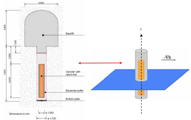
This modelling study deals with a system representative for an individual deposition hole of the KBS-3 concept, with its canister and buffer, as shown in Figure 2-2. The deposition hole is 1.75 m in diameter for a height of about 7.8 m. The canister is surrounded by several decimeters of bentonite buffer (0.35 m thick around, 0.5 m height below and 1.5 m above). The concrete bottom plate, as well as the backfill at the top of the deposition hole and in the deposition tunnel is not accounted for in the present study. The spent fuel package is assumed neither to be porous nor to be chemically reactive.
A fracture network can be formed in the crystalline rock due to geological history, and fractures may be intersected during the excavation of deposition holes. As in Arcos et al. (2006), a hydraulically active fracture plane is therefore assumed in the considered system, at about mid-height of the deposition hole. Solute migration will thus be driven by advective flow in the fracture and mostly by diffusion within the bentonite buffer.
Such a system presents a cylindrical geometry which is broken by the asymmetric flow field in the fracture plane. Since HYTEC cannot manage three dimensional grids, the system has been split into two complementary simulation grids:
− a first one, reported in Figure 2-3, corresponds to a horizontal cross-section at the level of the fracture plane with water flowing from left to right in the fracture plane. The cross-section does not
take into account the buffer in its full height but only a fraction equal to the fracture width (0.1 m). With this respect, the chemical and mineralogical evolutions of the simulated part of the buffer will be overestimated (geochemical changes propagate further for a given time period) since the fracture water cannot diffuse up and down, within the entire buffer volume;
− a second simulation grid accounts for the cylindrical symmetry (2D-cylindrical grid equivalent to a 3D grid) without explicit flow within the fracture (see Figure 2-4). A constant concentration constraint is used as a boundary condition in the fracture plane instead. This is correct for the upstream part of the fracture, but less for the downstream region, where species concentrations may change due to groundwater/bentonite interactions. One therefore may expect that the chemical and mineralogical evolutions in the buffer with time are slightly increased with this constant concentration assumption. To summarize, the geochemical evolution is overestimated by the calculations based on the cross-section grid. Overestimation means here an acceleration of the propagation of the chemical perturbations within the bentonite buffer, perturbation intensity itself being correctly estimated. This point is illustrated in section 3.1. The time periods resulting from simulations with the cylindrical grid should be closer to what could be expected and, except when that is mentioned, the time indications in the following text refer to the cylindrical grid.
In the cross-section grid, the average node size is about 0.05 m. In the cylindrical configuration, the node size in the bentonite zone is 0.05 m in the X coordinates (the width of the buffer) and 0.1 m in the Y coordinates (the height of the buffer).
2.4 GEOCHEMISTRY AND MINERALOGY
2.4.1 GROUNDWATERS
Interactions between the buffer and three distinct kinds of water have been investigated, as in Arcos et al. (2006): a reference groundwater (Forsmark), a high-salinity groundwater (Laxemar) and an ice-melting groundwater (Grimsel). In addition, a fourth type of water was considered, i.e. a dilute groundwater (similar to the ice-melting one) with various oxygen contents. An equivalent approach to that presented in Arcos et al. (2006) was followed in the present study to compute the composition of these groundwaters. Saturation indices were first determined with JCHESS from experimental data, and then partly adapted to modelling constraints.
The Forsmark groundwater considered in the reference scenario is a Na-Ca-Cl water type, as reported in Table 2-2, with a pH value close to neutrality and a reducing redox potential. Table 2-3 shows that the groundwater is close to saturation (equilibrium) with respect to calcite, dolomite, chalcedony/quartz, goethite and Ca-montmorillonite. The water is slightly undersaturated with respect to gypsum as well as siderite, whereas a noticeable undersaturation state is calculated for pyrite. Calcite and quartz are experimentally observed as minerals infilling the fractures; siderite which is close to the equilibrium with the water is likely to be present in the fracture (Arcos
et al. (2006)). Consequently, the Forsmark groundwater was pre-equilibrated with those three minerals prior to be
considered as a boundary condition at the fracture level. The recalculated chemistry remains obviously very close to the experimentally determined one, as shown in Table 2-2.
The high-salinity groundwater composition is modelled from Laxemar experimental data. This Na-Cl water presents a more alkaline and strongly more reducing signature than the Forsmark water, and is in close equilibrium with calcite and chalcedony-quartz, which are common secondary minerals found in fractures. For this reason, the modelled groundwater was set in prefect equilibrium with calcite and quartz. The water is strongly oversaturated with respect to pyrite and undersaturated with respect to gypsum. Reduced sulfur is the predominant species at such low pe values. However, according to Arcos et al. (2006), analytical data from Laxemar indicates that the dominant aqueous sulfur species are rather sulfate species. Therefore, it seems more realistic to redefine the pe of the system by forcing equilibrium with pyrite. The calculated chemical composition is detailed in Table 2-2. Diluted water may circulate in the fracture network during extended ice-melting periods. A possible chemical composition based on Grimsel data is found in Table 2-2. On the one hand, the ionic strength is two to three orders of magnitude below that of the previous groundwater ones. This is a clear indication of shallow origin. On the other hand, the pH is significantly more alkaline (around 9.6). Calcite and quartz were set in equilibrium with the recalculated groundwater.
The fourth type of water is derived from the previous dilute one, adding dissolved oxygen so as to assess the redox buffering capacity of the buffer versus an oxidative perturbation. The fugacity in oxygen is fixed to an intermediate value of 0.04, which assumes a 80 % consumption of the oxygen dissolved in a shallow water equilibrated with atmosphere. Two other alternative values, 0.001 and 0.2 (water fully saturated in oxygen) are also considered in the purpose of a sensitivity analysis. More details on this ‘oxidative case’ are given in section 5.1.
Figure 2-2. Schematic view of the KBS-3 disposal concept (SKB, 2006) and representation of the
simulated subsystem with an hypothetical fracture plane.
z
Figure 2-3. Calculation grid representative for the
cross-section at the level of the fracture plane.
Figure 2-4. Calculation grid representative
for the cylindrical geometry
(rotation around
the z axis, perpendicularly to the fracture
plane).
2.4.2 DEPONIT CA-N BENTONITE
The mineral composition of the Deponit CA-N bentonite (SKB, 2004) taken into account in the calculations is, by decreasing order of weight content, montmorillonite (81%), calcite-siderite (10%), dolomite (3%), gypsum (1.8%), quartz (2%) and pyrite (0.5%). It’s worth noting that this bentonite contains accessory minerals which strongly affect its pore water chemistry, especially at high solid/liquid (S/L) ratios. One should also specify that i) the amount of quartz includes the cristobalite content and ii) that the calcite-siderite amount was divided in 8 % of calcite for 2 % of siderite, which probably overestimates the siderite percentage.
The calculated pore water of the Deponit CA-N bentonite is reported in Table 2-2. Temperature was set to 15°C, the long-term value considered by SKB (SKB, 2006). This initial state considers a pre-equilibrium phase with the Forsmark groundwater. The equilibrium of the pore water is imposed with respect to calcite, dolomite, siderite, gypsum, quartz and pyrite. This leads to a Na-Ca-Cl water type, with a pH value close to neutrality and reducing conditions, similar though different from the Forsmark water. The pore water composition is in good agreement with the composition obtained by Arcos et al. (2006).
The pore water is also in equilibrium with the exchangeable cations of montmorillonite. The subsequent modelled occupancy ranges as Ca (41% in equivalent), Mg (33%), Na (24%) and K (2%). This distribution has to be compared to the experimental one (SKB, 2004), i.e. Ca (46%), Mg (29%), Na (24%) and K (2%). The equilibrium of dolomite, which is strictly imposed in the calculations, explains the moderate difference in the Ca/Mg ratio. The discrepancy of the modelling with the measured values becomes significantly worst if the EQ3/6 log K value of dolomite is used instead of the Nagra TDB one. Therefore, the choice of Nagra TDB log K for dolomite has been maintain throughout this study, leading to faster dissolution of this mineral with respect to the results presented in Arcos et al. (2006).
z [m]
To summarize, the dissolution and precipitation of the following set of minerals are considered in all the simulations dealing with the Deponit CA-N bentonite: the carbonates calcite, dolomite, magnesite and siderite; the sulfate gypsum; the silica oxide quartz; the iron minerals pyrite and alternatively ferrihydrite or goethite.
2.4.3 MX-80 BENTONITE
MX-80 bentonite is modelled from the data provided by SKB (SKB, 2004) with montmorillonite (87%), quartz-cristobalite (5%), gypsum (0.7%) and pyrrhotite (0.07%). Pyrrhotite (FeS) was considered instead of pyrite (FeS2) in the reactive transport calculations for convergence reasons. The consequence on the geochemical evolutions of MX-80 bentonite when interacting with the different waters considered in the present study is found to be insignificant, except for pe. Actually, the equilibrium of bentonite water with pyrrhotite instead of with pyrite diminishes the pe values by about 0.5 unit (-3.15 to be compared with -2.6 derived from pyrite).
Because of their incidence on the bentonite capacity to buffer geochemical perturbations, even if in small concentrations, and the relative uncertainties concerning their presence, calcite (0.7 %) and siderite (0.7 %) are considered in the context of a sensitivity analysis, as in Arcos et al. (2006). This induces changes in the aqueous iron and carbonate contents of bentonite pore water, as reported in Table 2-2.
The composition of the pore water of MX-80 bentonite is calculated with JCHESS (see Table 2-2). Temperature was set to 15°C, as for Deponit CA-N. The equilibrium is imposed with respect to gypsum, quartz and pyrrhotite and leads to a Na-Ca-Cl type of water, with a pH close to 7 and reducing conditions. This composition is in good agreement with that calculated by Arcos et al. (2006), except for the Na concentration, which is a little higher than in Arcos’ work (2.1e-1 mol/l vs. 1.6e-1 mol/l).
The modelled occupancy distribution of exchangeable cations is given as follows: Na (72%), Ca (18%), Mg (8%), K (1.5%). This distribution is strictly identical to the experimental ratio.
The simulations reported in the following chapters take into account the dissolution/precipitation of carbonates (calcite, dolomite and siderite), sulfate (gypsum), quartz and iron minerals (pyrrhotite and ferrihydrite).
2.4.4 WASTE PACKAGE AND HOST ROCK
As written above, the waste package was not explicitly taken into account in the calculations. This implies that, neither the uranium dioxide, nor the copper containers, is considered as solid phases present in the near-field environment. Similarly, the Host-rock minerals are not assumed to react with the different groundwaters and the bentonite pore water. Indeed, the rock-forming minerals are characterized by very low intrinsic dissolution kinetic constants as well as tiny reactive surface area, even in the damaged state induced by spalling.
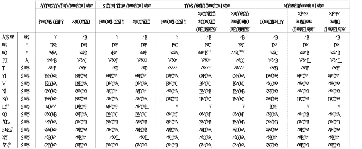
Table 2-2. Chemical composition of the groundwaters and bentonite pore waters.
Reference case groundwater High-salinity groundwater Ice-melting groundwater Bentonite pore water
Experimental Modelling Experimental Modelling Experimental
Modelling (reducing conditions) Modelling (oxidative conditions) Deponit CA-N MX-80 (without carbonates) MX-80 (with carbonates) Temp. °C - 15 - 15 - 15 15 15 15 15 pH - 7.2 7.2 7.9 7.9 9.6 9.6 9.6 7.0 7.0 7.0 pe - -2.4 -2.7 -5.1 -3.9 -3.4 -3.15(**) 11.6(***) -2.6 -3.15 -3.15 Eh V -0.15 -0.16 -0.29 -0.22 -0.20 -0.31 0.66 -0.15 -0.18 -0.18 I mol/L 0.19 0.20 1.7 1.7 0.001 0.001 0.001 0.25 0.29 0.29
Na mol/L 8.9e-2 8.9e-2 3.5e-1 3.5e-1 6.9e-4 6.9e-4 6.9e-4 7.3e-2 2.1e-1 2.1e-1
K mol/L 8.8e-4 8.8e-4 7.0e-4 7.0e-4 5.0e-6 5.0e-6 5.0e-6 1.6e-3 1.4e-3 1.4e-3
Ca mol/L 2.3e-2 2.4e-2 4.6e-1 4.7e-1 1.4e-4 8.0e-5 8.0e-5 2.9e-2 1.0e-2 1.0e-2
Mg mol/L 9.3e-3 9.3e-3 1.0e-4 1.0e-4 6.2e-7 5.0e-6 5.0e-6 3.2e-2 5.6e-3 5.6e-3
Al(*) mol/L 2e-10 7.5e-9 2.0e-9 1.0e-8 - - - 5e-9 - -
Fe mol/L 3.3e-5 2.9e-4 8.0e-6 8.0e-6 3.0e-9 3.0e-9 3.0e-9 3.7e-4 1.1e-5 1.0e-4
SiO2 mol/L 1.9e-4 6.0e-5 8.0e-5 4.4e-5 2.1e-4 8.0e-5 8.0e-5 6.0e-5 6.0e-5 6.0e-5
HCO3- mol/L 2.2e-3 1.5e-3 1.0e-4 4.8e-5 4.5e-4 4.7e-4 4.7e-4 2.3e-3 1.5e-3 4.0e-3
Cl- mol/L 1.5e-1 1.5e-1 1.28 1.28 1.6e-4 1.6e-4 1.6e-4 1.5e-1 1.5e-1 1.5e-1
SO42- mol/L 6.8e-3 6.8e-3 9.0e-3 6.0e-3 6.1e-5 6.1e-4 6.1e-4 2.6e-2 3.8e-2 3.8e-2
(*) Set in equilibrium with K-Feldspar; (**) fixed value; (***) O2 fugacity set to 0.04.
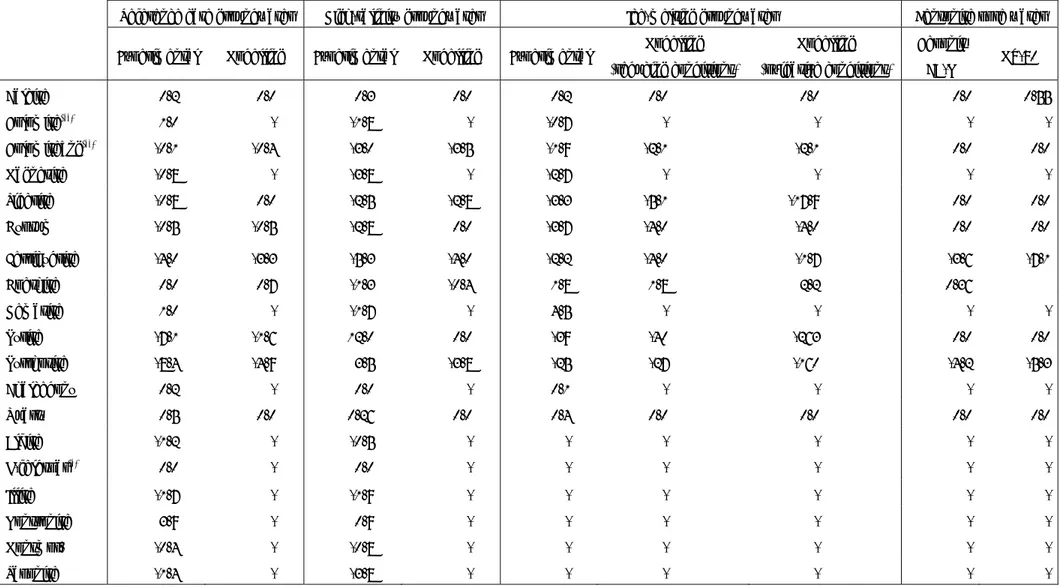
Table 2-3. Saturation indices calculated for groundwaters and bentonite pore waters.
Reference case groundwater High-salinity groundwater Ice-melting groundwater Bentonite pore water Experimental Modelling Experimental Modelling Experimental Modelling
(reducing conditions) Modelling (oxidative conditions) Deponit CA-N MX-80 Calcite 0.2 0.0 0.3 0.0 0.2 0.0 0.0 0.0 0.55 Dolomite(**) 1.0 - -1.8 - -0.7 - - - - Dolomite_ng(**) -0.1 -0.4 -3.0 -3.5 -1.9 -2.1 -2.1 0.0 0.0 Magnesite -0.8 - -3.8 - -2.7 - - - - Siderite -0.8 0.0 -2.5 -2.8 -3.3 -5.1 -17.9 0.0 0.0 Gypsum -0.5 -0.5 -2.8 0.0 -3.7 -4.0 -4.0 0.0 0.0 Ferrihydrite -4.0 -3.3 -5.3 -4.0 -2.2 -4.0 -1.7 -3.6 -7.1 Goethite 0.0 0.7 -1.3 -0.4 1.8 1.8 2.2 0.36 Hematite 1.0 - -1.7 - 4.5 - - - - Pyrite -7.1 -1.6 12.0 0.0 -39 -40 -263 0.0 0.0 Pyrrhotite -8.4 -4.9 3.5 -3.8 -25 -27 -160 -4.2 -5.3 Chalcedony 0.2 - 0.0 - 0.1 - - - - Quartz 0.5 0.0 0.26 0.0 0.4 0.0 0.0 0.0 0.0 Albite -1.2 - -0.5 - - - - - - K-feldspar(*) 0.0 - 0.0 - - - - - - Illite -1.7 - -1.9 - - - - - - Nontronite 3.9 - 0.9 - - - - - - Montmor. -0.4 - -0.8 - - - - - - Saponite -1.4 - -3.8 - - - - - -
(*) K-Feldspar equilibrium is set in the calculations. (**) Dolomite, log K from EQ3/6 TDB, Dolomite_ng, logK from the Nagra TDB.
2.5 FLOW AND SOLUTE TRANSPORT PARAMETERS
2.5.1 BENTONITES AND FRACTURE
The whole system was assumed to be fully (water) saturated since the beginning of the calculations, i.e. the transient saturation stage of the buffer was not simulated.
The flow and transport properties used for calculations are those selected in Arcos et al. (2006), detailed in Table 2-4. Although groundwater advection occurs in the fracture network, diffusion is the predominant transport process in both compacted bentonites because of their very low hydraulic conductivities (K = 1e-13 m/s, six orders of magnitude lower than in fracture). The selected effective diffusion coefficients are those of neutral or cationic species. For the cylindrical grid, the total exchange of the buffer pore water is found to be in around 2,000 y.
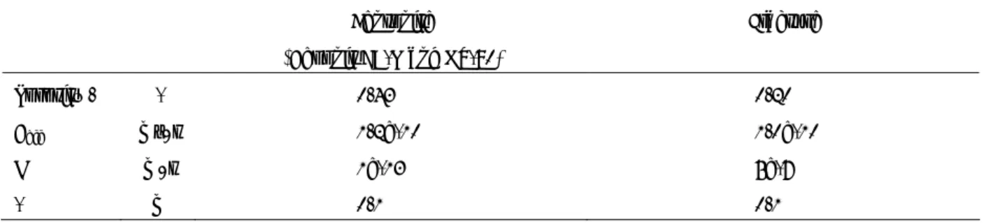
Table 2-4. Flow and transport parameters selected for bentonite and fracture zones.
Bentonite
(Deponit CA-N and MX-80)
Fracture
Porosity ω - 0.43 0.20
Deff m²/s 1.2e-10 1.0e-10
K m/s 1e-13 5e-7
α m 0.1 0.1
The calculated steady-state flow field is reported in Figure 2-5 for a hydraulic gradient of 0.002 m/m (value from Arcos et al., 2006). The bentonite ring behaves as expected as a hydraulic barrier, with an average velocity close to zero, diverting the water around. There is accordingly a local maximum in the Darcy velocity at the (3.5, 1 m) coordinates in the fracture plane. However, the Darcy velocity remains low, i.e. less than 0.1 meter per year.
Figure 2-5. Advective flow (Darcy velocity) in the fracture plane; coarser grid for a better
visualization of the flow field.
3 DEPONIT CA-N BENTONITE/GROUNDWATER LONG-TERM
INTERACTIONS
3.1 REFERENCE CASE, THE FORSMARK GROUNDWATER
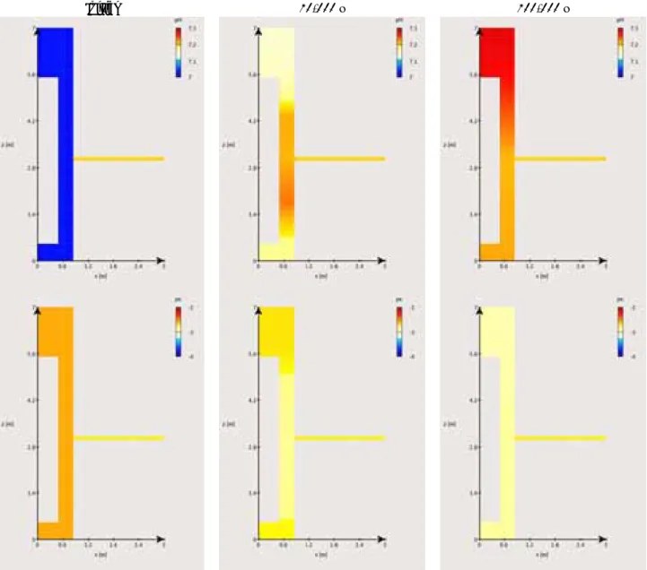
In the reference case, i.e. Forsmark groundwater entering the Deponit CA-N bentonite buffer, the Forsmark water slowly imposes its chemistry within the entire cylindrical volume of the bentonite buffer, from the bentonite zone around the fracture level to the other parts of the buffer. This interaction induces moderate changes in pH and pe values over the 100,000 y of simulation, as shown in Figure 3-1, pH increasing by 0.3 unit at the most and pe decreasing by 0.3 unit accordingly.
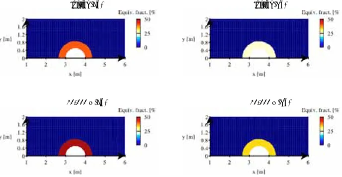
During this 100,000 y period, the exchangeable Na and Ca populations (Figure 3-2) both increase of approximately 10 % (respectively 24 to 35 % and 41 to 50 %) at the expense of the Mg and K cations. The K occupancy, which is whatever low comparatively to the others, moves from 2 to 1 %, whereas the initial Mg occupancy drops from 33 to 13 %.
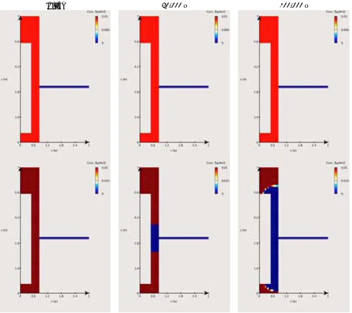
Regarding mineral modifications (Figure 3-3), one observes in the entire bentonite volume a progressive but complete dissolution of gypsum in 25,000 y and of dolomite in 85,000 y, while calcite content increases. It is worth emphasizing that dolomite dissolution probably results from the modelling approach, i.e. recalculation of Forsmark groundwater (Table 1-3), and the selection of an alternative log K value (section 2.4.2), and should be considered with some caution. The experimental data of the Forsmark groundwater indicates a sursaturation state for dolomite, arguing for the long-term stability of this mineral in the Deponit CA-N buffer. Dolomite dissolution occurs in a two-step process. Gypsum dissolution which is faster than dolomite dissolution yields a first concomitant decrease of one third of the dolomite content over the whole buffer in 25,000 y. This is followed by a second stage of dolomite dissolution, slower, leading to a complete depletion at 85,000 y. Siderite, pyrite and quartz contents are unchanged (i.e. stable on the long-term). Note that the dissymmetry (up versus bottom) within the bentonite core is transient and results from the asymmetrical distribution of bentonite around the waste package and the fracture plane.
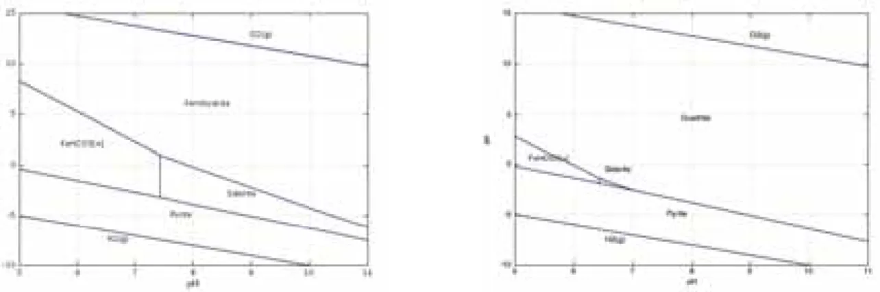
The processes responsible for these changes are mainly induced by the difference in aqueous sulfate and magnesium content between the Forsmark groundwater and the bentonite pore water. The aqueous sulfate concentration is lower (about 3.8 times) in the fracture than in the bentonite pore water. This concentration gradient induces a diffusion of sulfates out from the bentonite, and consequently gypsum dissolution as a supply in aqueous sulfates. Similarly, the lower aqueous magnesium content (about 3.4 times) in the fracture with respect to bentonite generates the out-diffusion of this species from bentonite. The depletion in magnesium within the bentonite leads to the dissolution of dolomite, which raises the aqueous carbonate and calcium concentrations and thus yields calcite precipitation. This last process results in the observed rise in pH, which in turns leads to a decrease in pe, as predicted by the Pourbaix pe-pH diagram of iron given in Figure 3-4 without any consequence on the content in redox sensitive minerals. These dissolution-precipitation reactions and the associated modifications in the aqueous chemistry of the bentonite pore water, i.e. aqueous Mg decrease and Ca supply, explain the
calculated re-organization of the cation occupancy in the montmorillonite exchanger. The Mg by Na replacement completes that by Ca, due to a slight in-diffusion of Na from the fracture to the bentonite. The dissolution of the accessory minerals does not yield to any significant changes in the porosity of the system, as indicated by Figure 3-5. The increase of porosity is less than 2 % and is essentially due to the dissolution of gypsum since most of the dissolved dolomite reprecipitates as calcite. The diffusion coefficient should not significantly change accordingly.
Globally, the chemical evolution of the bentonite buffer – driven by diffusion of the Forsmark groundwater – slowly occurs over the full bentonite height and reaches a quasi-steady state at the end of the simulation time. It is worth emphasizing that the chemical evolution within the buffer is smoothed down progressively, in a typical diffusion process manner, as the concentration gradients between the fracture and the buffer decrease (not thoroughly represented in the present report).
At last, the evolutions in pH, pe and exchanged cation populations calculated using the cross-section grid (Figure 3-6 and Figure 3-7) are given for illustration purpose. As mentioned in the previous section, the modifications are similar to those obtained with the cylindrical grid, although in shorter simulation times.
Initial 10,000 y 100,000 y
Figure 3-1. Reference case with Deponit CA-N bentonite: evolution of pH and pe over 100,000 y.
Initial 10,000 y 100,000 y
Figure 3-2. Reference case with Deponit CA-N bentonite: evolution of exchangeable Ca (top), Na
(middle) and Mg (bottom) populations over 100,000 y.
Initial 10,000 y 100,000 y
Figure 3-3. Reference case with Deponit CA-N bentonite: evolution of gypsum (top), dolomite
(middle) and calcite (bottom) contents over 100,000 y.
Figure 3-4. Pourbaix/pe-pH diagram of iron (Fe, HCO
3and SO
4concentrations identical to those of
the initial pore water of the Deponit CA-N).
Initial 10,000 y 100,000 y
Figure 3-5. Reference case with Deponit CA-N bentonite: evolution of the porosity over 100,000 y.
Initial Initial
10,000 y 10,000 y
Figure 3-6. Reference case with Deponit CA-N bentonite: evolution of pH and pe over the first
10,000 y.
Initial (Ca) Initial (Na)
10,000 y (Ca) 10,000 y (Na)