Raisins – towards general usability
and drivability for ViP platform
resources
www.vipsimulation.se
ViP publication 2014-5 Limited dissemination
Authors
Torbjörn Alm, HiQ Calle Isakson, HiQ
ViP publication 2014-5
Preface
The project Raisins - towards general usability and drivability for ViP platform resources was a collaborative activity between HiQ, the Swedish National Road and Transport Research Institute (VTI), Volvo Car Corporation (VCC), AB Volvo and Scania within the competence centre Virtual Prototyping and Assessment by Simulation (ViP). The project was financed by the ViP competence centre.
The project was headed by Torbjörn Alm at HiQ, which company also carried out the main part of the work.
However, without the participation from the other partners the project had failed to mirror the future needs for simulation in the Swedish automotive industry, so I would like to thank all partners who actively contributed to the project.
Linköping, April 2014 Torbjörn Alm
Quality review
Peer review was performed on 17 April 2014 by Arne Nåbo, VTI and on 16 May 2014 by Dennis Saluäär, AB Volvo. Torbjörn Alm has made alterations to the final
manuscript of the report. The ViP Director Lena Nilsson examined and approved the report for publication on 30 September 2014.
ViP publication 2014-5
Table of contents
Executive summary ... 7 1 Introduction ... 9 1.1 Simulator-Based Design ... 9 2 Project purpose ... 11 2.1 Presumptions ... 11 3 Methods ... 12 4 Results ... 134.1 Review of “Real Life Scenarios for Simulations, Methods and Environment - Industrial needs” (ViP publication 2010-3) ... 13
4.2 Resource inventory ... 19
4.3 Workshop results ... 20
4.4 A visionary software approach for the ViP simulation platform ... 20
5 Discussion ... 24
6 Conclusions ... 26
List of figures
Figure 1: The principle steps of the SBD process. The dotted arrows symbolize iterations, which are key elements in the process together with the comparative
approach (Alm, 2007). ... 10 Figure 2: “Future fields” overview – relations, important aspects, basic comments and priorities. The prioritizing was set as 1 = most important and 5 = least important. (From Fischer et al., 2010a)... 16 Figure 3: Schematic view of a virtual prototype for SBD. Sensors are generally replaced by signals from the simulator. Most actuators are also simulated functions, while the middle layer could be a real SIL function at any stage of development. The interface resources could be anything realized as a software/hardware cockpit function (Alm, 2007). ... 18 Figure 4: The cloud in the figure represents the global collection of data produced by all the modules in the simulation that can be used as input by other modules. For example, modules A, B and C produce data that can be used by all other modules in the
simulation. Module C2 only consumes data and is only present in the simulation for the purpose of comparison with module C. ... 21 Figure 5: Layer principles. Each module consists of three layers; Sub-system,
ViP publication 2014-5
List of tables
Table 1: Questionnaire results on experiences with the usage of driving simulators. Representative choice of commented features divided by topic area. (From Fischer et al., 2010a). ... 14 Table 2: Questionnaire results on experiences with the usage of driving simulators. Number of comments according to the different topic areas. (From Fischer et al.,
2010a). ... 15 Table 3: Inventory results. Green marked objects are available at ViPForge (2013). ... 19 Table 4: Tool chain features related to the proposed architecture. ... 23
ViP publication 2014-5
Raisins – towards general usability and drivability for ViP platform
resources
by Torbjörn Alm and Calle Isakson, HiQ Ace AB
Executive summary
The original purpose of the Raisins project was to make an inventory of the gathered software resources of ViP as they appear at the ViPForge, analyse their usability for re-use and propose a technical roadmap. In addition to this an investigation of industrial needs was planned to grip prioritization and complementation demands from the
industrial partners. During the start-up process the idea of a more visionary approach for the ViP simulation software came up as an alternative path to take.
The Raisins project was divided into four separate activities; inventory and evaluation of existing resources at ViPForge, review of the report from the early ViP project “Industrial Needs”, workshops with each of the industrial partners, and finally an activity at HiQ to sketch an alternative software approach.
The results could be summarized to a conclusion where two alternative development paths for future simulation software in the ViP community are possible to take. The first path is to continue with the on-going incremental approach, where we have to accept the existing structure of the simulator platform but add new and improve existing resources. The second, alternative path, is to start from the beginning based on the existing
knowledge and the industrial requirements of today. The new start will probably also include re-use of existing platform modules. This second alternative may be necessary to choose if the ambition is to have a common national simulator platform to be shared by all ViP partners and also internally used by each partner. It is the authors’ opinion that obtaining this goal is crucial for the future existence of ViP.
It is clear that the latter approach is not possible to start based on ViP funding. Thus, if the ViP partners choose to support this alternative, a project application to another source of funding should be made as early as possible to have this project up and running when ViP phase 3 starts.
ViP publication 2014-5 9
1
Introduction
The automotive industry is rapidly expanding the use of simulation in the product design process. The main reason for this strategy is to shorten the time for development and make safe design decisions as early as possible. A bonus effect is less demands on producing physical prototypes for field testing. One important background factor in this trend is also that the vehicles have changed from being pure mechanical products to be complex systems with computerized functionality. Such systems/functions have been much more suited for simulation approaches in the design phases than the mechanical functions and are more in focus according to the ViP agenda.
The simulation could either be carried out on a mathematical level on computers or using human-in-the-loop simulators. The latter approach is relevant for testing
functional concepts where the driver is a part of their performance. For ViP this is the focus area and Simulator-Based Design (SBD) is the process the centre aims at further develop.
In this ambition both methodology and technology need to be addressed. Methodology to give safer background on how to approach different design questions together with methods for analysing simulation results, and technology for offering a simulator platform with high performance values.
At an early stage of the ViP centre it was decided that the VTI simulator platform should be the basis for further development activities despite the fact that no other ViP partners at that time were using this platform internally. Since then a number of ViP projects have refined and strengthened the platform and produced additional resources to make the SBD process more efficient. However, the experience from many project activities is that there are further steps to take in order to reach a platform level good enough to meet the industrial demands on usability and efficiency.
It should be emphasised that the use of simulation is not only a business for the automotive industry but also for organisations with focus on the infrastructure. Their interest is mainly on road design, traffic regulation and supporting systems outside the vehicles. Such areas are definitely possible objects for SBD and some projects with this focus have been carried out in ViP. However, the organisations in this area have not yet come so far in the utilization of the SBD concept.
1.1
Simulator-Based Design
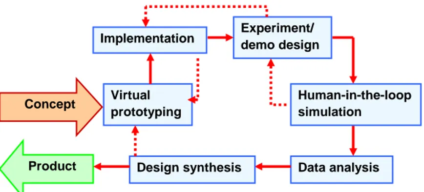
The Simulator-Based Design (SBD) process is equal to the ViP agenda on “virtual prototyping and assessment by simulation” and includes a number of identifiable process steps to take a product idea all the way to a production state (Figure 1). The product itself can be a built-in subsystem of a vehicle or some new operator interface solution. In the same way it may be some infrastructure system or component like a traffic information facility or a new road solution. This means that the prototyped object could be of different kinds. For vehicle objects the result will be implemented in the vehicle model, while for infrastructure objects the prototypes will be included as an environment model. Both kinds of models always need to be realized to make the simulation complete. If the vehicle function is in focus, this will be manipulated, while the environment model will be kept constant. For environmental studies the opposite approach normally is adapted.
Comparative approaches are always recommended since it is more or less impossible to have absolute results telling how good a solution will be in absolute terms in the real world setting. But when two (or more) alternatives are compared in exactly the same conditions the winning alternative is always possible to identify (relative validity). It should be mentioned that absolute results are not possible to achieve in any test setting. Only long term field studies will give such answers.
Figure 1: The principle steps of the SBD process. The dotted arrows symbolize iterations, which are key elements in the process together with the comparative approach (Alm, 2007).
To conclude, the process described above is the process that has to be supported in every step by the technical platform. This means both by hardware and software. The hardware solutions refer mainly to the cockpit and should vary from simple desktop equipment via fixed-base complete vehicle settings to high-end sites with moving platforms. Here, it is always important to choose the sufficient (not more) level for the test, not the least for economic reasons. This aspect of the technical platform is not further discussed in this report since we could anticipate numerous variations depending on the aims of work in the specific organization or team as well as which simulation equipment is available.
The software, which the Raisins project is focused on, could have the same content irrespective of hardware solution. The variance between different site levels will be constituted by the number and kinds of software modules in use, but all modules could be included in the complete software platform.
Product Experiment/ demo design Virtual prototyping Concept Data analysis Design synthesis Human-in-the-loop simulation Implementation
ViP publication 2014-5 11
2
Project purpose
The purposes of the Raisins project were to:
Bring the original industrial needs to the surface as they appeared in the early ViP project “Industrial Needs” (Fischer et al., 2010a) and translate these needs to platform demands.
From this basis investigate any changes or new demands by the industrial partners.
Make an inventory of existing ViP platform resources and compare their feasibility against the industrial needs.
Propose a technical roadmap for future platform development.
It should be mentioned that the outcome of the project has changed slightly related to the original purpose due to achieved knowledge during the project. This has affected the two last points above. The inventory part mirror the ViPForge status in rough outline and the roadmap came to be two alternative directions for future platform development to choose between.
2.1
Presumptions
The main purpose of the ViP technical platform from an industrial perspective is to be able to support Simulator-Based Design (SBD) processes among the ViP partners as efficient as possible. This purpose does not exclude using the platform in Human Factors research.
The full benefit of the technical platform will appear when all industrial partners have brought the platform to internal use to a significant extent. This will also positively influence the willingness to invest in continuous platform development beyond the on-going ViP phase 2.
3
Methods
Four complementary approaches were used in the Raisins project. First, a report review was carried out. The review was based on reports from earlier ViP projects, mainly the “Industrial Needs” project (Fischer et al., 2010a), to catch the needs as they were identified in 2010. These needs were expressed in terms of what the industrial partners wanted to do in their simulation activities. In our following analysis work these terms were translated into software requirements.
The second activity was an inventory of existing assets at VTI, mainly as they appeared at the ViPForge. The inventory focused on various usability aspects. The main
information source for this part of the project came to be based on the experience collected at HiQ from the ViP simulator establishing project at Scania in which a
number of HiQ experts were engaged. The resulting inventory list was iterated with VTI and refined in a couple of steps.
The results from these two activities made the basis for a document (a first draft of chapters 1, 2, 4.1 and 4.2 of this report), which was distributed to the three industrial partners Scania, Volvo Car Cooperation and AB Volvo as preparation for the third step in the project, workshops at the three companies. The main purpose of these workshops was to get their confirmation and prioritisation of simulator requirements (based on Fischer et al., 2010a) as well as their supplementary suggestions. Another purpose was to get the opportunity to discuss SBD in the internal industrial processes.
The last activity in the Raisins project was to discuss and sketch an alternative approach for future development of the ViP platform, an alternative to keeping on with the
incremental approach to make the existing platform more useful for SBD projects. This activity was carried out with participation of some of the experts in simulator
architecture at HiQ. As information background we used the industrial demands, as they had appeared during the above mentioned workshops together with experience from corresponding SBD activities in the aerospace industry. It should be mentioned that SBD has been utilized in the aircraft design processes since the early 1970’s and the first author of this report was involved in this from the beginning (Alm, 2007). Today several HiQ consultants work with the continuous development of such simulator platforms to make the aircraft design process even more efficient. The parallel between the two business areas, automotive and aviation industry, is obvious. The products are complex vehicle systems operated by humans.
To conclude, the Raisins project came to end in two alternative approaches for the future development of the ViP platform. The first alternative is to continue with incremental work to make the existing platform more useful, while the second alternative is to take a more radical approach and make a new start.
ViP publication 2014-5 13
4
Results
In this chapter results from the four activities will be presented. The literature review will be the first part followed by the inventory results, a short summery of the
workshops, and finally the result of the architecture activity at HiQ. The literature review was mainly based on the report from the “Industrial Needs” project (Fischer et al., 2010a), but some conclusions have been influenced by the reports from the ViP projects “Tools” (Fischer et al., 2010b) and “SimHarm” (Bergström & Nåbo, 2012). It may be noticed that these projects were ended some years ago, but since the focus was on needs and not on the existing technique the results were supposed to have good relevance also today. This assumption was later confirmed at the project workshops.
4.1
Review of “Real Life Scenarios for Simulations, Methods and
Environment - Industrial needs” (ViP publication 2010-3)
The project was managed by Martin Fischer at VTI and participating industries were VCC, AB Volvo, Saab Automobile and Scania. Since much of the industrial experience was shared on a more detailed level by VTI, through long collaboration with the
industrial partners (hosting simulator projects), it was natural to gather information also from people at VTI.
In the following, essential parts of chapter 2 in the “Industrial needs” report (Fischer et al., 2010) is cited and will be commented.
“Experiences and development needs
The approach to find out about both positive and negative experiences with the usage of driving simulators was to use a questionnaire addressing the following questions:
Which features did you miss in the simulator environment you used?
Which features where there but with a too low quality?
Which features helped you a lot to successfully perform the simulator experiment?
Which features did you use very often?
Table 1 gives a representative choice of commented features and in Table 2 all topic areas are listed together with the respective numbers of comments.”
Table 1: Questionnaire results on experiences with the usage of driving simulators. Representative choice of commented features divided by topic area. (From Fischer et al., 2010a). T o pic a rea nr. Topic areas
/Feature Missing or low quality features Useful and often used features
1 Road Design
‾ Road surface/friction correlation between visual, sound and motion ‾ Mixed road types, easy to
design (e.g. through a GUI)
+ Standard track (mixed road types)
Surrounding Traffic ‾ Realistic behaviour of surrounding traffic + Autonomous traffic 3 Visuals
‾ Large field of view, better resolution
‾ Realistic and diverse environments and vehicles
4 Vehicle Dynamics
‾ Accurate longitudinal motion ‾ Advanced models /incl. active
safety systems)
+ simple models (easy to adjust)
5 Motion / Force
‾ Motion sensation for critical manoeuvres
‾ Motion sensation for intersections
‾ Realistic speed perception
+ General usage of motion, steering force and road feedback
6 Sound
‾ Sound of surrounding vehicles ‾ Usage of real radio for
distraction tasks
+ Noise and vibration correlation
7 Data analysis
‾ Standardised log data base ‾ Automated analysis tools ‾ Online calculation of ISO
measures
+ Time markers, cameras and voice instructions
+ Measures: reaction times, steering wheel reversal rate, lateral position, speed, standardised subjective scales 8 HMI ‾ Head-up display (or similar)
HMI devices
+ Programmable multi-purpose buttons + Flexible displays
ViP publication 2014-5 15
Table 2: Questionnaire results on experiences with the usage of driving simulators. Number of comments according to the different topic areas. (From Fischer et al., 2010a). T o pic a re a nr.
Topic areas / Feature
M is sing E x is ting bu t lo w qu a lity H elpf ul O ft en us ed
1 Road Design (type, surface, course, …) 3 7 1 1
2 Surrounding Traffic (traffic flow, autonomous vehicles, …) 3 3 1
3 Visuals (resolution, field of view, sight distance, …) 6 6
4 Vehicle Dynamics (complexity, car type …) 1 2 1
5 Motion / Force (vehicle accelerations, road roughness, steering
force, …) 3 10 5
6 Sound (engine sound, wind noise, surrounding traffic, warnings,
…) 3 3 1
7 Data analysis (measures, tools, …) 3 2 4
8 HMI (flexibility, display types, input devices, …) 1 3 1
9 Scenarios (special events, weather conditions, traffic conditions,
…) 6 1 2 2
10 Test participants (test driver data base) 1 1
11 Sensors (real or modelled sensor integration) 3 2 1
12 General (costs, overall features) 1 1
Figure 2 below shows how the participants in the “Industrial Needs” project (Fischer et al., 2010a) looked upon areas for future simulation activities, which areas and how important they were considered at the time for the project (2009 – 2010).
Figure 2: “Future fields” overview – relations, important aspects, basic comments and priorities. The prioritizing was set as 1 = most important and 5 = least important. (From Fischer et al., 2010a).
In Appendix 3 of the “Industrial Needs” report the participants listed expectations towards the ViP centre. The expectations with bearing on the simulator software have also been considered in the conclusions presented below.
“List of expectations:
Simulation development
Demonstration/proof-of-concept of certain applications
Support networking of Swedish simulators
Common software tools
ViP publication 2014-5 17
Comments to the cited chapter
It is obvious that many comments/areas of the reviewed ViP report were coupled to physical issues around specific simulator sites. For example, visual limitations/field of view have/has no other coupling than to the number of projectors/screens of the site in mind. In the virtual environment model “everything” is always available and could be presented.
The above view is also relatively static. It is more or less impossible to have
“everything” ready and fixed for every upcoming simulation need. Instead there should be a focus on having basic assets which could be easily adjusted to the specifics of each study. If this is possible to do for most of the areas above the set-up time for each simulation should be radically reduced.
In the introduction part of the report all industries gave their view on using simulators in the product design process. The notion of scalability was not mentioned there (but in the above list of expectations), however all partners presented views, going from low to high fidelity simulators, which could be translated to the three levels desktop, fixed-base and moving-fixed-base simulators but also to other test facilities as HiL and SiL rigs. It should be emphasized that improvements of the ViP platform have been made since the remarks were listed, but here the ambition is to list requirements as they are and not take into deeper account whether these requirements are met or not or to which degree.
Conclusions
In the following conclusions, based upon the “Industrial Needs” report (Fischer et al., 2010a), are made and have been translated into technical requirements. This translation is necessary to make in order to present the simulator requirements in terms which could be used as a to-do list for future platform development.
(1) Scalable software solution
To make the transition between desktop, fixed-base and moving-base simulators smooth and easy, the conclusion will be to have a common scalable software solution in order to move applications (new products/subsystems) from earlier concept phases to more mature solutions, where the need for a more complete vehicle system is necessary for integration reasons.
(2) Basic assets
There should be a focus on having basic assets (virtual worlds, roads, scenarios etc.) which could be easily adjusted to the specifics of each study instead of aiming for a complete library covering every case. If this is possible to do for the
interesting areas the set-up time for each simulation should be radically reduced.
(3) Open source vehicle model
This issue has been discussed many times after the “Industrial Needs” project and has been included as a part of some project proposals but with no resulting
activities so far. Existing models have so far been industrial property.
(4) Autonomous vehicles – driving behaviour and vehicle models
The meaning of this conclusion is not completely clear, but our interpretation is that there is a need for other (than “own ship”) vehicles in scenarios with good
means/tools to give these vehicles certain individual behaviours mirroring a realistic traffic situation. This includes both vehicles following traffic rules and vehicles which break rules. To realize such possibilities in an efficient way there is a need for a scenario generation tool with such capability.
(5) Virtual prototypes and SiL/HiL integration
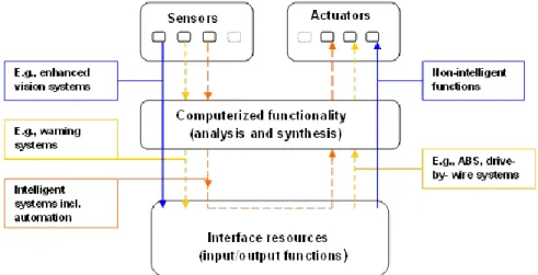
This demand puts the pressure on the software architecture, but also on the cockpit realization. It must be easier to plug in functions on each prototype level (see Figure 3 below) without any need for manipulating the simulator kernel or going to the workshop with the cockpit.The physical cockpit interaction resources should be software based. Interfaces must be specified and possible to meet by the
prototyping teams. This also points out the need for documentation of the simulator software which is lacking today.
Figure 3: Schematic view of a virtual prototype for SBD. Sensors are generally replaced by signals from the simulator. Most actuators are also simulated functions, while the middle layer could be a real SIL function at any stage of development. The interface resources could be anything realized as a software/hardware cockpit function (Alm, 2007).
(6) Virtual worlds and scenarios (shared libraries)
This is an important feature and at the same time a good motivation for having a partnership like ViP. The ambition goes much further than to use resources for demonstration purposes. Since the time for the “Industrial Needs” project (2009 - 2010) resources of this nature have been added to the ViPForge and the growth is still on-going due to contributions from various projects. As mentioned earlier, it is even more important to have tools for developing and/or manipulating such assets.
ViP publication 2014-5 19
(8) Standardisation
A common interest seems to be the standardisation and common use of tools, definitions or models in order to share efforts and results of further developments. Another advantage will be the ability to change between simulator environments or easily substitute certain simulation modules.
(9) Platform architecture
One suggestion based on the experiences from the “SimHarm” project (Bergström & Nåbo, 2012) was to move the vehicle dynamics out from the simulator kernel. This could be extended to include the complete scenario. Today the scenario is managed directly in the kernel, which makes scenario design very difficult for developers outside simulator teams.
4.2
Resource inventory
The inventory part of the Raisins project was carried out mainly based on the experience the HiQ team gained from the simulator project at Scania, where the ViP software platform was implemented. Later the inventory results were discussed and adjusted at a meeting with the simulator experts at VTI. It may be added that specific assets
developed in earlier projects are not included in Table 3 below. Such assets could be valuable for re-use but are more or less impossible to find without knowledge of the specific project content. This means that the following list does not cover every resource or asset available through the ViPForge.
Table 3: Inventory results. Green marked objects are available at ViPForge (2013).
Object Type O/S Language Comments
VISIR Graphics engine Windows/Linux C++ Usable module at ViPForge SIREN Sound engine Windows/Linux C++ Usable module at ViPForge Graphical objects Load files Windows/Linux N/A Exist to some extent
VTISim/kernel Simulator Windows/Linux C++ Not available at ViPForge Vehicle models Model Windows/Linux C++ Not available at ViPForge Cockpit interface Interface Windows/Linux C++ Not available at ViPForge Audio files Load files Windows/Linux N/A Not available at ViPForge Textures Load files Windows/Linux N/A Not available at ViPForge System control
panel
GUI Windows/Linux C++ Not available at ViPForge
General documentation
Documentation N/A English Documentation on
architecture and instructions are not available at
ViPForge
Scenario Documentation N/A English Not available at ViPForge
In addition to the inventory list in Table 3 above, some general remarks were mentioned by the inventory team.
Standards
Standards, e.g. coordinate systems and interfaces used, shall be documented in order to enhance the usability of available ViP platform components.
Packaging
The ViP platform shall be packaged for delivery in order to enhance accessibility. This shall include installation instructions and user documentation.
Simulator kernel
Dynamics models and scenario functions shall be extracted from the simulator kernel in order to enhance the possibility to realize a default delivery package that can be
modified by each user (simulator owner).
ViPForge structure
Should not be project oriented. The content ought to have a structure based on type of asset and should also be presented in that way in an introductory table of contents, where selection of objects for re-use can be done.
4.3
Workshop results
Parts of this report were put together (see chapter 3, Methods) and sent out to the contact persons (the reference group) at the industries for further distribution internally prior to the physical meetings. One meeting at each industry was held and gathered a number of participants from relevant fields. In total just above ten persons from the industries participated. Also representatives from VTI and HiQ participated and the workshops were headed by the first author. The inventory list and the conclusions of the report review were discussed and one could conclude that there was a common support from all industries for the conclusions made so far (see pages 17-19).
One specific opinion from the industry side was that a key issue for a successful
application of SBD was to minimize set-up times. For the moment this requirement has not reached a satisfactory level in the ViP platform. Also the need for simulator experts in most of the SBD steps is considered as a bottle-neck which needs to be addressed. These requirements need to be in focus in the future development of the ViP technical platform, and refer both to what to develop (as concluded earlier in this report) and also to how these steps should be designed to satisfy the industrial demands.
4.4
A visionary software approach for the ViP simulation platform
ViP publication 2014-5 21 The ViP platform is not flexible or configurable enough for the purpose to
support the SBD design process at different stages in an efficient way.
In the following the visionary approach is presented very briefly. To go deeper will put demands on efforts beyond the limits of the Raisins project.
4.4.1 Main structure
The proposed architecture is based on a selection of collaborative modules. Each module represents a separate part of the complete simulated system at different levels e.g. engine, transmission, surrounding traffic, traffic lights etc. The architecture is based on a scheduled publish/subscribe design pattern where each module is scheduled for execution based on the real time needs. Each module publishes a selection of produced data and subscribes to selection of needed data from other modules (Figure 4).
Each module is configurable to produce data using a generic alias. This means that multiple modules can produce and publish the same kind of data, e.g. ABS brake force. In that case several ABS-modules can subscribe to the same input data but publish output under different names. Hence the simulator can rely on the data from one of the ABS-modules while the data from ALL ABS-modules are logged for comparison. The modules can be located on the same machine or LAN/WAN-network.
The publish/subscribe design pattern approach is the same on all levels; simulator kernel/IO, inside simulator kernel and even at the top level between simulators. The scheduling can differ depending on implementation level.
A simulation configuration description is used to specify what modules to load and how data flows are connected. Several descriptions can be used as templates in order to handle different simulator configurations and minimize set-up times.
Figure 4: The cloud in the figure represents the global collection of data produced by all the modules in the simulation that can be used as input by other modules. For example, modules A, B and C produce data that can be used by all other modules in the simulation. Module C2 only consumes data and is only present in the simulation for the purpose of comparison with module C.
Model needs - Configuration
- Synchronization (e.g. frequency and order) - Data
Run multiple versions of a model by publishing under different names (C and C2 in the figure)
A - C2, model examples:
A = Engine, B = Transmission, C = ABS 1, C2 = ABS 2
Benefits of proposed design
The modular design based on the presented publish/subscribe design pattern gives the following benefits:
The simulation can be distributed over a set of computers in a LAN/WAN-network for performance purposes.
Performance comparison between several module variants, e.g. ABS-systems, is driven by the same simulation.
Common design at different implementation/abstraction levels gives better understanding and maintainability.
4.4.2 System principles
Each module consists of three layers; Sub-system, Component and Model.
As could be seen in Figure 5 below, a ”soft” model or a ”hard” physical system is encapsulated within a design artefact called Component. The Component is an adaptor between the interface of the Model/system and the interface of the encompassing Sub-system design artefact. This Sub-Sub-system design artefact handles all requirements related to publish/subscribe and scheduling in relation to the rest of the simulation.
Figure 5: Layer principles. Each module consists of three layers; Sub-system, Component and Model.
The Model layer represents either a software model of a physical system, e.g. ECS, or the actual physical system itself with the real ECU hardware and production software. Using the Component and Sub-system layers the module expose the same behaviour related to the rest of the simulation. This layer principle also makes it possible to build
ViP publication 2014-5 23 A variety of tools for software model production can be used and encapsulated
in a standard way.
4.4.3 Use-case example
One key feature of the suggested architecture is the possibility to support tool chains going from desktop facilities via SiL and HiL rigs to full scale platforms (“top-of-the-line” simulators). At all levels the same core simulator kernel is used, while a number of completing modules is available but not all in use at every stage of the vehicle design process. Which modules should be in use are defined by the needs of the system prototype in the specific test. At all levels the purpose is to test and refine the design results.
The use-case example in Table 4 shows how the proposed new architecture supports the industrial need for efficient simulator-based processes and offers a higher level of flexibility than is possible today where different simulator platforms are used at each level of simulation.
Table 4: Tool chain features related to the proposed architecture.
Desktop (SiL) Fixed base (SiL) Fixed base (HiL) Motion base (SiL) Motion base (HiL)
In this case the complete
simulation can be executed from the desktop for the purpose of scenario or concept development. A suitable selection of modules is used based on desktop computer performance, e.g. a module that implements a generic low performance cost vehicle dynamics model. All modules encapsulate software models.
Fixed-based simulator with a representative cockpit and OTW (Out The Window) solution. The simulation vehicle is repres-ented by modules encapsulateing software models. A selection of modules can be upgraded for higher performance since more computer power is available. Example: One module that represents the complete vehicle dynamics can be replaced with several modules that together represent the same thing (engine, transmission, steering, brakes and so forth).
Fixed-based simulator with a representative cockpit and OTW (Out The Window) solution. The simulation vehicle is represented with a mix of modules that encapsulates software models and real ECU hardware (including production software). Simulator with motion platform with a representative cockpit and OTW (Out The Window) solution. The simulation vehicle is represented by modules encapsulating software models. Simulator with motion platform with a representative OTW (Out The Window) solution. The simulation vehicle is represented by modules encapsulating a real physical vehicle to a larger extent.
5
Discussion
The existing ViP simulator platform is usable for activities in the area of SBD.
However, with reference to the resource inventory (chapter 4.2) and the industrial needs (chapter 4.1) there are many steps to take when the goal is to have a useful tool set which makes it possible for other than platform experts to have easy access. This statement refers to the simulator software. The corresponding cockpit solutions are not analysed in this project since they are strongly coupled to the different sites. However, it should be mentioned that in many cases the cockpit solutions cause more limitations in the application of SBD than the existing software. This is due to the fact that most cockpits are just ordinary vehicle cockpits (referring to the driving interface) with limited possibilities to introduce different interface alternatives without workshop efforts.
The software inheritance in the ViP community has its origin at VTI. When this
software platform was designed, the main purpose was to support projects in the area of behavioural science, where the participants (experiment drivers) were manipulated. In this, driving performance and other physical or psychological measures were in focus. This sphere of activities set the underlying demands on the software as well as on the physical construction.
SBD brings other requirements, since here the vehicle and the infrastructure is the target for manipulation while the driver is one source for measuring together with performance measures on the complete man-machine system.
The perhaps most evident requirement this altered focus brings is the need for easiness in the procedure to “change the vehicle or the infrastructure”. Alternative vehicle sub-system designs or road designs must be possible to plug in to the simulation software very quickly without changing anything else. The answer to such demands is to offer module-based software architecture beyond the structure which now is coming up through the ViP project SimArch2.
A corresponding reasoning is also relevant for the simulator cockpit. In evaluating new system concepts it is more important to have a very flexible and programmable driver interface than it is to have an exact hardware copy of the specific vehicle.
In addition, “easy to change” the scalability requirement is crucial for the industrial application of SBD. To have the possibility to take new product/system designs all the way from the desk to full scale environments using the same simulator platform is extremely time-saving and as well very important for tool maintenance due to limited need for multiple software test platforms.
Number three of main requirements is the need to minimize set-up times. The solution of such demands, besides the need for modular architecture, is coupled to the supply of
ViP publication 2014-5 25
way to take if the ViP community will support a strategy of using a common simulator platform also in the internal design work and thus support a national simulator platform. Such a choice should be decided to match the start of ViP phase 3. This decision ought to be followed by a simulator systemizing project funded by Swedish authorities and the applying parties. In this project more quantitative requirements for usability,
accessibility etc. should be decided.
It should be emphasized that choosing the second alternative should also include investigation on how to make the best use of components and knowledge from the existing platform as well as do some benchmarking. There are a number of commercial simulators on the market and simulators developed internally by different automotive manufacturers. To get an overview of the capabilities of such simulators could be a valuable information input to the proposed Swedish project.
6
Conclusions
Identified main needs/requirements concerning the ViP platform are:
The procedure to change the vehicle or the infrastructure shall be easy, and realized via a module-based software architecture enabling plug-in of alternative solutions.
Changing the scalability shall be easy, and enable the possibility to take new product/system designs all the way from the desk to full scale environments using the same simulation platform.
Set-up times shall be minimized, by supplying efficient test setting-up tools which require no or little simulation expertise to use.
ViP publication 2014-5 27
References
Alm, T. (2007). Simulator-Based Design – Methodology and vehicle display
applications. Linköping Studies in Science and Technology, Dissertation No. 1078. Linköping, Sweden: Linköping University
(http://www.diva-portal.org/liu/theses/abstract.xsql?dbid=8465).
Bergström H., & Nåbo A. (2012). ViP SimHarm - "White book"
Simulatorharmonisering och förbättringar. ViP publication 2012-1. Linköping, Sweden: the Swedish National Road and Transport Research Institute (VTI) (and internal www.vipsimulaton.se).
Fischer, M. et al. (2010a). Real Life Scenarios for Simulations, Methods and
Environment - Industrial Needs. ViP publication 2010-3. Linköping, Sweden: the Swedish National Road and Transport Research Institute (VTI) (and internal www.vipsimulaton.se).
Fischer, M. et al. (2010b). Technical Platform for support of ViP activities – Tools. ViP publication 2010-4. Linköping, Sweden: the Swedish National Road and Transport Research Institute (VTI) (and internal www.vipsimulaton.se).
www.vipsimulation.se
ViP
Virtual Prototyping and Assessment by Simulation
ViP is a joint initiative for development and application of driving sim-
ulator methodology with a focus on the interaction between humans and
technology (driver and vehicle and/or traffic environment). ViP aims at
unifying the extended but distributed Swedish competence in the field of
transport related real-time simulation by building and using a common
simulator platform for extended co-operation, competence development
and knowledge transfer. Thereby strengthen Swedish competitiveness
and support prospective and efficient (costs, lead times) innovation and
product development by enabling to explore and assess future vehicle
and infrastructure solutions already today.
Centre of Excellence at VTI funded by Vinnova and ViP partners VTI, Scania, Volvo Trucks, Volvo Cars, Swedish Transport Administration,
Dynagraph, Empir, HiQ, SmartEye, Swedish Road Marking Association Olaus Magnus väg 35, SE-581 95 Linköping, Sweden – Phone +46 13 204000