• Developing critical materials as well as evaluating new manufacturing technology for LCD displays • Defining the requirements for a polymer particle based spacer system based on Conpart’s unique
technology for particle design and synthesis
Nanoscale Surface Treatments to
Participants 1. Project owner
CIT Recycling Development AB, Sweden
2. Project manager
CIT Recycling Development AB, Sweden Christian Adås
3. Project participants
Participants in the NICe financed part of the project. VTT, VTT Processes, Finland
Harri Joki
Swecard AB, Sweden Gustav Franklin
Participants in the parts of the project that aren’t financed by NICe. Conpart AS, Norway
Helge Kristiansen and Keith Redford
SINTEF, SINTEF Materials and Chemistry, Norway Christian Simon and Bente Tilset
Institute of Catalysis and Surface Chemistry, Polish Academy of Sciences, Poland Piotr Warszyński
Fact sheet
Title and project number: PARFUN - Nanoscale Surface Treatments to
Functionalise Polymer Particles, Project number 07148
Abstract: The PARFUN project consortium has investigated the potential
application of mono-sized polymer particles as spacers for a new generation of high performance LCD screens. The consortium has generated particles with a very narrow size distribution and with properties tailored to the application. The particles have a size of the order 3 to 5 micrometer in diameter. Particles have been
characterized extensively with respect to mechanical and surface properties. In order to produce conducting spacers the particles have been coated with nickel and gold. The particles have been incorporated in small prototype LCD cells and these cells have been characterized with respect to performance. No significant distortion of the liquid crystal crystallization is observed in the vicinity of the particles and ion leakage tests showed no leakage.
The consortium has developed a novel technology for the placement of particles on the LCD substrate. For high performance screens it is desired that the spacers be located only in the non-active parts of the screen: between the pixels in the dark framing regions. A patent application will be filed in the first part of 2011 to protect the IPR related to this method.
The two “end-users” associated with the project, Swecard AB and 3M, both have expressed interest in following up this technology and consider it for their future products.
Keywords: Polymer particle, LCD, liquid crystal, Spacer, Inkjet printing, surface
chemistry, mechanical properties
SINTEF, SINTEF Materials and Chemistry
PO Box 124, Blindern, N-0314 Oslo, Norway Phone +47 40003730 Fax +47 22067350 Author: Bente Tilset Bente.t.tilset@sintef.no
Conpart AS Lahaugmoveien 1,
NO-2013 Skjetten, Norway Phone :+ 47 64 00 40 34 Fax: +47 63 84 09 06 Authors:
Helge Kristiansen, helge@conpart.no Keith Redford, keith@conpart.no Swecard AB Kungsgatan 33 111 56 Stockholm, Sweden Phone +46 8 221190 Fax +46 8 221196 gustav.franklin@swecard.com VTT, VTT Processes Sinitaival 6 Tampere, PO Box 1607 FI-33101, Finland Phone +358 20 722 3313 Fax +358 20 722 3498 Author: harri.joki@vtt.fi CIT Recycling Development AB
Chalmers Teknikpark
SE-412 88 Göteborg, Sweden Phone: +46 31 772 4373 Fax: +46 31 82 70 35 Authors:
Christian.adas@cit.chalmers.se Helena.tunell@cit.chalmers.se
Institute of Catalysis and Surface
Chemistry, Polish Academy of Sciences Polska Akademia Nauk
ul. Niezapominajek 8 30-239 Krakow, Poland Phone +48 12 6395-121 Authors : Piotr Warszyński ncwarszy@cyf-kr.edu.pl
Executive Summary
Main Objectives
The main objective of the project has been to develop critical materials as well as to evaluate new manufacturing technology for LCD displays. The consortium partners consider this project to be successful. Success is documented in so far as a new technology has been developed for the placement of spacer particles that will be patented in 2011.
Modern LCD screens are built as a series of layers including a thin film of liquid crystal material. As the name implies this material is a liquid and tends to flow under the influence of gravity. For a screen to function this liquid film must be maintained with an even thickness over the whole area of the screen. In the majority of modern LCD screens the film thickness is maintained by a matrix of spacer columns
distributed over the entire area of the screen. These spacers are produced by a photo-resist technology in which a large proportion of the photo-resist film is etched away: A costly process with a high wastage of material. The main goal of this project has been to define the requirements for a polymer particle based spacer system based on Conpart’s unique technology for particle design and synthesis. The challenges have been to produce conducting and non-conducting spacer particles with pre-defined mechanical and electrical properties and locate these particles at specific sites on the LCD screen (between the illuminated pixels). Challenges have included placement of the particles and adhesion to the underlying substrate. This has been achieved
without affecting the liquid crystal’s function and without introducing species that interfere with the electrical characteristics of the screen.
The material technology has included the development of a new spacer particle based on advanced polymer particle technology. Particles with diverse compositions have been produced and evaluated as spacer materials. Particles have been produced with an extremely narrow size distribution. A Coefficient of Variation (CV) of less than 2% where CV=Std.Dev/Ave. Particles have been produced as insulating spacers and as metal coated conducting spacers. A new technology has been developed to place these particles at specific locations on a substrate and to adhere these particles in a way that does not adversely affect the properties of the liquid crystal.
Method/implementation
The group consisting of Conpart as, Norway; Swecard AB; 3M Svenska AB, Sweden; Institute of Catalysis and Surface Chemistry of the Polish Academy of Sciences (ICSC), Poland; VTT, Finland; SINTEF, Norway and CIT Recycling Development AB, Sweden (formally known as the Swedish LCD Center AB) have worked in close collaboration during the whole project period.
The PARFUN group have mapped the requirements for an optimum particle based spacer technology for high performance LCD screens. Using the expertise available
in the group and in the group’s extensive contact network a prototype system has been developed and tested in lab scale LCD screens. Work has involved regular physical and telephone meetings and has involved the exchange of materials and personnel between member laboratories. The combination of industry and research institutes has functioned extremely well. The work has involved polymer particle synthesis, mechanical testing, advanced surface characterisation, surface
modification, metallisation, colloid characterisation, rheology, inkjet technology, ink formulation LCD prototype manufacture and LCD characterisation. Activities have been effectively distributed among the partners and there has been a free exchange of ideas and results.
Results and conclusions
The project has utilized advanced methods and characterization techniques to
describe the bulk and surface properties of micron sized polymer particles. Using this knowledge the particles have been successfully modified to produce a new
generation of spacer particle specifically designed as spacers for LCD screens. The spacers have the mechanical properties we believe to be optimal for the application, a size distribution that is superior to any products on the market today, and tailor made surface that is optimized for the application.
A new technology has been developed to place and fix these particles at the desired locations on a LCD screen. A patent will be applied for during the first half of 2011 to protect this new technology. This application will be filed by the project
coordinating company Conpart as, Norway.
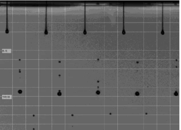
Patterning of polymer substrates for LCDs. a) shows the desired pattern, with d = 200 µm and b) the obtained particle pattern, also with d = 200 µm.
Dissemination of results
Results from the project have been published in refereed journals, at international conferences and through a seminar with invited participants. A patent is under preparation and the scientific background to this patent will be published after the filing of the patent.
Recommendations
Conpart as will take responsibility for the securing of property rights for the newly developed technology. Contact has already been made with a leading LCD producer in Asia with aim to bring this technology closer to the market.
Further development of the technology developed in this project is necessary. The project members have every intention of securing funding for a continuation of this work and cooperation. Steps have been taken to increase the size of the consortium with the aim of increasing the industrial participation and to supplement the
academic team. There is a shared benefit and responsibility in securing a continuation of this activity.
WP1: Development of polymer particles with adhesive properties to glass and plastic substrates (WP Leader: SINTEF)
Task 1.1: Development of multifunctional nanosized particles and capsules with adhesive properties, and suitable “activation” processes
SINTEF has developed and patented a class of functionalized nanoparticles, called FunzioNano. These are made from hydrolyzed organosilanes as depicted
schematically in Figure 1. The nanoparticles typically have a silica-based core, with organic functional groups on the surface.
modification
Nanoparticles with modified amine goups (MHAPS)
Nanoparticles with amine groups (HAPS)
. . . . . . . . . . SiO1.5 + NH2 NH2 NH2 NH2 NH2 NH2 N H2 N H2 N H2 N H2 SiO1.5 NH2 NH2 NH2 NH2 NH2 NH2 N H2 N H2 N H2 N H2 SiO1.5 N H2 Si OEt OEt OEt + H2O
- EtOH HAPS: BASIC PARTICLES
MHAPS: 1stGENERATION
Figure 1 Schematic representation of Funzionano preparation.
In the Parfun project, a composite with titania cores, Ti-HAPS, was chosen for introductory studies of nanoparticle adhesion to Conpart particles. These
nanoparticles were made in a two-step process, where a titania core was coated with aminopropylsilane and hydrolyzed. The particle size of the resulting sol was 20 nm. Methods for controlled adsorption of polymers or polyelectrolytes on Conpart particles were developed. In this manner, the surface charge of the particles could be controlled, as shown in Figure 2.
latex Conpart pH 0 2 4 6 8 10 12 14 z eta potential [ mV ] -60 -40 -20 0 20 40 60 + PSS
Figure 2 Covering Conpart particles with the polyanion PSS changes the zeta potential from +25 to -40 mV.
This line of work was not followed further, since control of surface chemistry was achieved by modifying the preparation procedure for the particles themselves, see Task 1.3 below.
Task 1.2: Deposition of nanosized particles/capsules onto polymer particles
The aminofunctional Ti-HAPS nanoparticles were attached to the Conpart particles, as shown in Figure 3. High concentration of nanoparticles gave high coverage and problems related to particle agglomeration (Fig. 3 a). Lower concentrations gave improved results, with only a thin nanoparticle coating (Fig. 3 b).
a) b)
Figure 3 Conpart particles with a) high HAPS and b) low concentration of Ti-HAPS
Experiments for up-scaling production of Ti-HAPS made us aware of HSE issues related to the large use of organic solvents in the production process. In addition, the Ti-HAPS coated particles did not adhere well to the PI-coated substrates. Several different chemical variations were suggested to improve the performance of
nanoparticle or capsule covered microparticles. But since other methods for attaching particles to glass and polymer substrates were assumed to work well enough while being more industrially applicable, this line of work was not followed up further.
Task 1.3: Characterisation and modelling of (modified) surfaces.
The surface composition of polymer substrates for use in flexible LCDs was studied, as well as the surfaces of commercially available spacer particles. These analyses gave a good background for understanding the adhesion mechanisms that could be exploited in the Parfun project.
The control of surface properties was vital to the success of the project. Large efforts were therefore focused at understanding and adjusting the chemistry of the Conpart particles themselves. The zeta potential of the initial particles was unstable, as shown in Figure a). After adjusting the production procedure for Conpart particles,
a) b)
Zeta Potential (Sample no.:38.0004-5)
-40,0 -30,0 -20,0 -10,0 0,0 10,0 0 2 4 6 8 10 12 pH Z e ta P o te n ti a l (m V ) Day 1 Day 2/3 Day 4 -100 -90 -80 -70 -60 -50 -40 -30 -20 -10 0 10 0,00 2,00 4,00 6,00 8,00 Z e ta ( m V ) pH AA029-1 Washed day 1 Washed day 2
Figure 4 Zeta potential of Conpart particles as a function of pH a) at the beginning of the project, showing instability over time and b) at the end of the project, where particle charge had been stabilized by adjusting particle synthesis procedure.
Introductory lab-scale experiments were done to see whether we could modify LCD substrates with patterns of Conpart particles. Both surface chemistry and particle concentrations were varied to optimise deposition conditions. The goal was to obtain the pattern in Figure a). After deposition, the particle pattern in Figure b) was obtained. These lab-scale preliminary results were considered to be very promising, and the patterning procedure was therefore adjusted so that jet printing could be used to upscale the process for LCD applications. Details are shown in the reporting of WP3.
Figure 5 Patterning of polymer substrates for LCDs. a) shows the desired
pattern, with d = 200 µm and b) the obtained particle pattern, also with d = 200 µm.
Attempts have been made to measure the adhesion between Conpart particles and LCD substrates by colloidal probe Atomic Force Microscopy (AFM). In this method, a particle (Conpart microsphere) is attached to the tip of the AFM and brought into contact with the relevant surface. The force between the microsphere and the surface under investigation is measured, as depicted in Figure . Due to problems with finding an appropriate glue to fix the Conpart particles to the AFM tips, only introductory measurements with micronsized glass beads have been performed.
a) b)
Figure 6 Measuring principle of colloidal probe AFM. Part a) shows how the AFM tip with a microsphere attached is brought into contact with a surface and b) shows the corresponding force measurement.
Theoretical modelling of interactions between clean particles and glass/polymer surface has been done. Results show that interactions between large particles are not affected by the charge on the surface that they are deposited on. When the particle size decreases, however, the interaction between neighbouring particles is strongly affected by the charged plane. For microspheres from Conpart, these effects will not be important when working in aqueous solutions. They could, however, be important if deposition is done from weakly polar solvents.
Similar modelling of nanoparticle modified surfaces was not done, since this line of practical work was abandoned (see Task 1.2)
WP2: Development of polymer spheres with metal-like surfaces (WP Leader VTT)
To function as a conductive element, the particles have to be plated with a suitable metal which has the required electrical and mechanical properties. Metals which have been used as coatings were nickel (Ni) and gold (Au).
The final metal thickness will probably be of a few hundred nanometers to provide the necessary conductivity during the bonding process. The thickness varied between 50 nanometers to one micro meter.
The metal plated particles have been characterized with SEM, AFM, XPS and
mechanical testing of single particles. The conductivity (volume resistivity) of coated particles were measured with 4-wire setup
Task 2.1: Surface treatment of polymer particles.
To obtain a good adhesion to the polymer particle specific surface treatments have to be used. Particle which have been used in all experiments were from Conpart. In
general these particles were acrylic and some of samples were specially treated (functionalized). The particle sizes were between 3 – 5 µm.
Most relevant pre-treatments for these kind of polymer particles is two step
procedure. Firstly sensitizing the particle surface, secondly activation of the surface. Sensitizing was done by tin(II)-chloride, SnCl2. After sensitizing the surface is
activated by palladium(II)-chloride, PdCl2. Both steps were done in acidic condition.
Before these sensitizing/activation step the polymer particles were rinsed with de-ionized water and sonicated. Normally the sensitizing and activation were done separately in that order but simultaneous phase is also possible.
Task 2.2: Metallization process.
The metallization was done using electroless deposition. This means that the coating metal was reduced to the surface of polymer particles in strictly controlled process. The metal salts used were nickel sulfate, NiSO4 · 6H2O and tetra-chloro auric acid
(HAuCl4). The reduction reagents used were both sodmium hypophosphite and
sodium succinate. The solutions were acidic and pH changed from 6.5 to 3.4. Different temperature and reaction times were used.
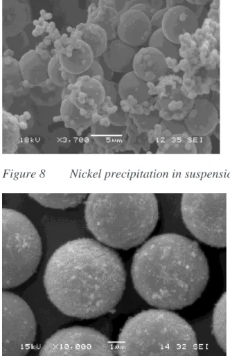
Electro deposition of gold on such fine particles proved difficult. This line of approach was less succesfull than the electroless method. Electroplating has been performed on particles down to 200 micron. Smaller than this have not been possible. Some example of coated particles
Figure 8 Nickel precipitation in suspension: No coverage of particles
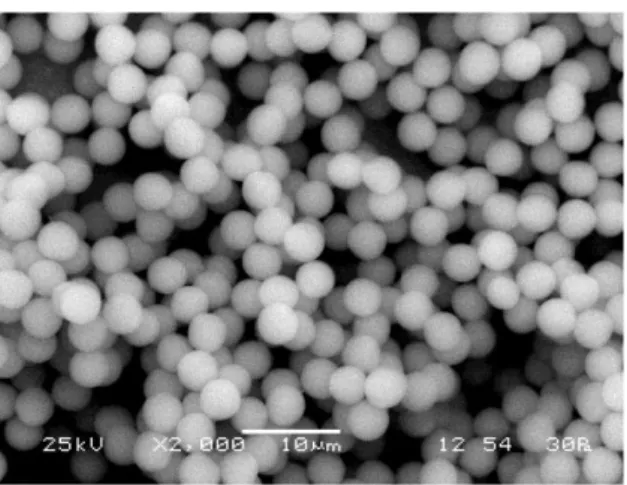
Figure 9 Even coating of nickel
Some example of volume resistivity values measured
Ω d2 pi L(cm) ρ AA028 514 1,677 3,141593 0,05 13540 700 1,677 3,141593 0,05 18440 660 1,677 3,141593 0,05 17386 AA029 73 1,677 3,141593 0,02 4807 36 1,677 3,141593 0,02 2371 35 1,677 3,141593 0,02 2305
Figure 10 Mechanical testing of individual nickelcoated polymer spheres. The red curve is the uncoated reference particle
Task 2.3: Surface treatment of metallized polymer particle to avoid agglomeration and enhance processability.
Metallised particles can be unstable under storage. Agglomoration and oxidation particaly under humid conditions can cause problems with loss of functionality. Nickel coated particles are best plated with a protective layer of gold immediately after production. To prevent agglomoration and to aid re-dispersion the gold surface may be reacted with a short chain mercaptan. Some loss in surface conductivity may be observed if too much is added or if the molecular weight is high.
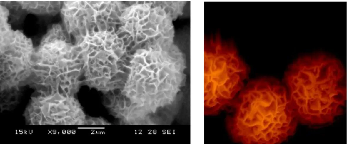
Figure 11 Example of “coral” like structure of Ni-coated particles after storage
WP3: Implementation of the new “materials” into products (WP Leader SLCDC)
Task 3.1: Develop set of specifications for spacer particles
LCD manufacturing involves the use of spacers to maintain a highly uniform gap between the two glass or plastic substrates forming the display. The following general properties are required by spacers:
Sharp particle diameter distribution
Maintaining an appropriate hardness
o The spacer should not be crushed due to pressure
o The spacer should not be so hard that it destroys the layers
The spacer should not move on the substrate
Liquid crystal should align well around the spacer
Chemical resistance towards materials in the display
Absence of contamination
o Spacers should be free of any impurities that could reduce the specific resistance of the liquid crystals
Thermal stability
Appropriate coefficient of thermal expansion and specific gravity, close to that of the liquid crystal
Appropriate dielectric constant and refractive index
When spacer particles are randomly distributed over the surface it involves several drawbacks. One is that the density of spacers will vary over the substrate and cause slight variations in the gap. Also the spacers located in the active area may cause reduced contrast of the display as they are actually replacing the liquid crystal fluid as well as distorting the liquid crystal around the spacer. To overcome some of these problems, photo spacers have been developed to replace random distribution of spacer particles. Photo spacers are made of photo-definable materials and are positioned on the non-active areas in the display, the black matrix, by a process similar to that of the lithographic patterning process. The major advantage of this method is that even and predetermined density and location of spacers can be obtained, leading to less light leakage and higher contrast ratios, but a disadvantage is the rigidity of spacers causing problems when used in flexible displays. Also there is an increase in the number of process steps compared to traditional spacer
application as well as an increased environmental impact due to large volumes of photo-definable chemicals and solvents used in the process.
However as compared to photo spacers, the conventional polymeric bead spacers are considered easier to handle, having better properties and being less expensive. Therefore there is a possibility that the market will return to polymer bead spacers when a technology is established for positioning the spacers in the desired places. Using inkjet technology the material waste is low and the number of process steps
can be kept at a minimum, making it a cost worthy alternative to the photo spacer process. Changing from one substrate design to another is straightforward and requires no additional tooling cost.
It is difficult to give accurate specifications of spacers as they must be tested for each application. 3M and Swecard have specific demands on for example size, colour, temperature and pressure resistance.
Task 3.2: Testing of “dry” spacers in real applications
Initial tests comparing Conpart spacer to commercially used spacers
Tests were performed to determine if Conpart spacers have suitable LC-aligning properties. The effect of the spacers on LC alignment must be comparable to that of other spacers. Furthermore there must be no leaking or reaction with LC.
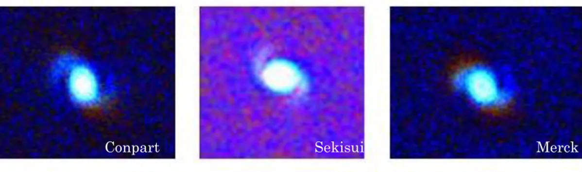
Standard test cells were made in clean room according to the following procedure. ITO coated glass substrates were cleaned in ultrasonic bath. Polyimide was used as alignment layer. It was spincoated on the substrates, baked in oven and rubbed to define the direction of alignment. Spacers from Conpart, Sekisui and Merck were wet sprayed on half of the substrates while a UV sensitive sealing frame was
dispensed on the others. Two substrates were put together to achieve cells where the rubbing directions of the two substrates are perpendicular to each other. The sealing frame was cured by exposing to UV-lamp for 2 minutes. The cells were vacuum filled with LC fluid.
Figure 32 Conpart, Sekisui and Merck spacers in liquid crystal cells of 4.5 µm size.
Microscope pictures show that there is no obvious difference in LC alignment seen between the different spacer types. The Conpart spacer seems to be mechanically intact and maintain the correct cell gap during manufacturing and usage. There are no signs that the spacer is not compatible with the LC fluid.
Ion leakage test
If there is a leakage of ions from the spacers this will affect the long term
performance of the display. To test any leaking of ions from the spacers, standard test cells were filled with LC fluid that had been exposed to different spacer particles for 2 weeks. Cells filled with non-exposed LC were used as reference. The
Merck Sekisui
dissipation factor of liquid crystal cells at 1 kHz, 0.1 V was measured. The values are followed from 0ºC to 100ºC (above the phase transition) and down to 0ºC again with a speed of 1ºC/min. The dissipation is caused partly by losses in viscosity when the LC is reoriented and partly by movements of ions. If the ion content is large, the effect of ion movements is dominating. The dissipation due to ion movements rises when the temperature rises, so the measurement are made in a temperature chamber allowing the temperature to be raised above the clearing point and then cooled again. All tested cells are comparable at room temperature, but at elevated temperature all cells exposed to spacers have higher dissipation than the non-exposed ones. However there is no significant difference between the cells exposed to different types of spacers. This indicates that the ion leakage of the Conpart spacer is comparable to that of the commercially used spacers for LCDs. The ion content was considered acceptable for all cells, although it depends on what the cells are to be used for as some applications are more sensitive than others.
Adhesion test
It must be determined if spacer adhesion to substrate is stable over time when immersed in liquid crystal as well as if spacer adhesion to substrate is comparable to that of other commercial adhesive spacers.
By far the most widely reported manual means to measure adhesion of layers to surfaces is a tape pull test. The number of particles before/after pull test indicates the degree of adhesion. An adhesion measurement method has been developed and measurements have shown that adhesion between Conpart particles and substrate with polymer are similar in strength to other commercial adhesive spacer particles. The adhesion is not affected by long time exposure (3 months) to the liquid crystal fluid.
Task 3.3: Develop and test of inkjet procedures
The inkjet equipment available at CITRET uses a Xaar shear mode piezoelectric drop-on-demand inkjet technology. With the drop-on-demand process, electric signals are applied to generate ink droplets only when needed. Piezoelectric inkjet technologies work by applying an electrical pulse passing through piezoelectric crystal or ceramic wall whereby the ink chamber deforms and squeezes an ink droplet from the nozzle. In a shear mode print head it is the shear action that deforms the piezoceramic plates against ink to fire the droplets. A XJ126/50 print head with 126 active nozzles was used. The drop volume typically delivered by the print head is 50 pl.
To evaluate a suitable solvent for inkjet printing experiment, several different mixtures were prepared for testing at XAAR. The following ink properties were known to be a suitable starting point to begin inkjet experiments:
boiling point preferably above 150°C
surface tension 32-50mN/m
The goal was to find a suitable solvent system and to see whether different molecular weights and concentrations of the polymer (high Mw=750000, medium Mw=70000, low Mw=2000) worked in the print head. The functionality of the different inks with the Xaar inkjet print heads was evaluated using a microscope rig with stroboscopic illumination, to visualize the ink droplets in flight leaving the nozzle plate. The nominal print head-substrate distance is 1 mm. There is a tendency for the high molecular weight polymer that some channels shoot the drops a little crooked. For the medium and low molecular weight all nozzles shoot straight. There are small satellite drops but with the speed used they will end up in the same position as the main drop so they will not cause any problems.
Figure 13 Stroboscopic image of drop formation for 15%EtOH-85%EtGl. 500 ppm polymer MW70000.
For different types of displays the inkjet pattern for precise positioning of spacers might differ. In a LC-shutter an array of dots seems to be a good pattern. For a TFT display the polymer and spacer should be placed for example below the black mask in narrow rectangular areas. For a passive display with a matrix of pixels there are areas between the pixels where the ink and spacer can be placed. In a passive segment display ink and spacer can be placed between the segments.
Figure 14 The picture to the left shows ink jet drops printed with 340µm distance and the picture to the right is an enlargement.
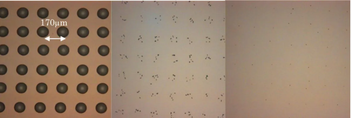
Inkjet printing of polymer is performed on 3M glass plates and Swecard plastic foils (both ITO and polyimide coated), followed by particle deposition. Particles seen outside the printed areas ranged from 0% to 12% of the total amount of particles. Different concentrations of polymer were ink jetted to PI glass substrates to see the limit for attaching particles. Varying the polymer concentration did not affect the “dried drop diameter”.
Figure 15 Inkjet printing glass substrate. To the left directly after printing. In the middle high concentrations of spacers. To the right low concentration of spacers.
3M is satisfied that the spacers mainly are in the printed areas and that the number of spacers/dot could be decreased from about 30 in the first tests to a few in the latest tests. Future improvements are possible by using print-heads with smaller drop volumes.
Swecard pixels are 340µm large and the polymer was inkjetted mixing 340 and 170µm distances to position the spacers in the interpixel areas.
Figure 16 Microscope picture directly after inkjetting of polymer (to the left) and after deposition of spacers (to the right)
Swecard finds the method very interesting. They are satisfied that the particles are in the correct place and stay there. Also they are satisfied to see that the cell switches as expected.
WP4: Dispersion and rheological studies of particle suspensions (WP Leader Conpart)
One method for particle placement is by the direct ink-jet printing of a dispersion of particles. This method is considered as commercially viable and is being promoted by companies such as Hitachi Chemical Corporation and Sekisui, both from Japan. The polymer particles concerned are of diameter 3 to 5 micron and of a density of about 1.25g/cm3. At this density and size these particles are not small enough to be considered as colloidal but are still greatly influenced by collisions with solvent molecules. These particles in suspension tend to sediment under gravity, which can cause problems for instance during deposition of particles in a suspension.
Inkjet for spacer deposition
The industrial inkjet printers relevant for LCD applications are based on the use of a piezoelectric material. Typically each element in the printer-head consists of a rectangular cavity, placed vertically between to walls that can be actuated by piezoelectric forces. These cavities or chambers are filled with the ink, and a nozzle is positioned at the end of the chamber. When a voltage is applied, the piezoelectric material changes shape, which generates a pressure pulse. By optimizing the driving pulse depending on the type of liquid, a droplet of ink will be ejected from the nozzle. When inkjetting particle suspensions with these types of inkjet heads, a possible sedimentation of particles can take place due to the near stagnant fluid. However, recently a new type of printer-head has been developed, in which the chamber is located horizontally, and a continuous flow of the ink passes through the channel, eliminating the problem with sedimentation of particles. The ink is jetted out of a hole placed centrally in the chamber. This technology allows better control of the drop formation, as well as smaller droplets. Advanced inkjet printer heads have individual calibration of each jet, giving a very good volume uniformity. Typical drop volume uniformity is better than 2%.
Figure 17 Reproducibility of inkjet droplet volume
By inkjet, a small group of spacers can be placed at well controlled positions.
Meeting with Chunghwa Picture Tube and ChiMei Innolux this autumn confirms a very strong interest towards the use of inkjet technology for applying spacers to the LCD. The main driving force is cost, as the photo-spacer technology requires very expensive equipment as well as a large waste of expensive materials.
Spacer placement density
The pressure balance across the display substrates can be expressed by: pAtm = pLq - “p”Spacer
where pAtm is the atmospheric pressure, pLq is the pressure in the liquid crystal, which
is dependent on vertical position due to the density of the liquid crystal. “p”Spacer is
the effective pressure exerted by the discrete positioned spacer particles.
When applying spacers to the LCD, there are two factors that must be considered. First, the total amount of spacers must be sufficient to avoid a “global” deformation of the glass, due to gravity. Typically numbers are 10000 balls per cm2. However, also due to the thin substrates used, each group of spacer particles must be separated by a maximum distance to avoid local deformation of the substrate. We have calculated typical spacer distance for both glass and polymer based displays. For glass displays, where the glass thickness is typically 0,7 mm, the each group of spacers needs to be placed with a separation less than typically 3 mm. For thin and flexible polymer displays, the spacers should be placed closer than 0,5 mm.
Task 4.1: Study the effects of particle concentration and surface properties on dispersion rheology.
We have studied the rheology of a suspension based both on a theoretical approach as well as an experimental approach. The theoretical approach was done in a close collaboration between Conpart and Sintef.
The suspensions of relevance to inkjetting of spacers, consist of nearly monodisperse polymer spheres with a diameter in the range 2 – 6 µm. These suspensions are on the border line between being colloidal and non-colloidal suspensions, i.e. where Brownian motion is of importance. Brownian motion is relevant when thermal displacement is a sizeable fraction of the linear dimension of the particle during typical experimental time ranges. Also the interaction between the dispersed particles depends on the nature of solvent and on the surface properties of the particles. Most highly crosslinked polymer particles in water behave as compact rigid spheres, as water is a poor solvent in this case. In a good solvent such as benzene these particles swell to a soft and deformable sphere. However, adding surfactants to the particles can give rise to different kinds of interaction potentials between the (colloidal) particles.
Two forces that are always present are the attractive van der Waals force and a repulsive hard-core interaction. The strength of the van der Waals forces is relatively short ranged, but can lead to irreversible aggregation of the suspended particles. To prevent this flocculation, there is two ways of stabilizing a dispersion:
Steric stabilization by adsorption of polymers that is well soluble in the dispersion medium.
Electrostatic stabilization by the introduction of charged groups onto the particles' surface.
For inkjetting the viscosity should be about 7-15 mPa*s. One important factor is that the shear rates of an inkjet are very high, of the order of several thousand per second. Normal shear testing is performed at shear rates of the order of 1/s. This means that normal equipment for viscosity measurements is not sufficient. However as suspensions with relatively low volume fraction tend to behave as Newtonian fluids, with viscosity independent of shear rate, this should not be a serious concern for inkjetting of spacer.
With a typical printing distance of 1 mm (for glass substrates), each jet of “spacer ink” should contain approximately 10 spacer particles. Given a particle diameter of 3 micron, the volume fraction of spacers in the ink will be approximately 2,5 % for a 6 pico-litre drop. This should be within the Newtonian regime.
We have also measured the relative viscosity change as a function of a wide range of particle concentrations at low shear rates. Typical results are shown below.
Figure 18 Total (complex) viscosity as a function of volume fraction of spacer particles. The line graphs correspond to theoretical models, with [η]=2.5 and Φm=0.65. The symbols correspond to total viscosity 2 [1]
Task 4.2: Evaluate suitable dispersants (solvents and surfactants) for the inkjet process.
To obtain a good control of the position of the spacer particles, the maximum droplet size and the surface tension and the evaporation rate of the solvent is critical. As long as the liquid film is thicker than the particle diameter, the particles will be free to move in the liquid droplet. A typical liquid flow pattern will be as shown in figure … The figure illustrates that evaporation is mainly taking place along the “triple-line” substrate – liquid – air (vapour). The result is a relatively fast (linear velocity) Marangoni (surface) flow towards the top-centre of the droplet (blue arrows), where the temperature is minimum, and a much slower “bulk” flow of fluid towards the “triple-line”. Particles in the bulk liquid will have a relatively slow transport towards the “edges” of the droplet. Once the thickness of the liquid film is less than the particle diameter, the particle will get “stuck”.
Figure 19 Drying of a droplet containing spacer particles
This transport is the origin of the well-known “coffee stain” effect. However, particles in the surface (not fully wetted) will be transported towards the centre of the droplet.
A “worst case” spreading for a 3 micron particle in a 6 Pico-litre droplet will be within a diameter of 50 micron.
Task 4.3: Develop spacer dispersions that are suitable for inkjet.
Conpart particles have proven to be relatively flexible with respect to dispersing media. So long as the chosen fluid is non-swelling stable dispersions have been formed. Mixtures of alcohols and water provide suitable dispersing media for inkjetting. Choice of composition enables a wide variation of viscosity and drying rate. Viscosity can be further modified by the addition of oligomers. High molecular weight material should be avoided as the solution becomes visco-elastic. This results in the droplet of liquid remaining attached to the print head. This can result in the droplet dividing into several particles or in the extreme the droplet never detaching and being dragged back to the print head.
[1] “Spherical polymer particles in isotropic conductive adhesives – A Study on Rheology and Mechanical Aspects”, H. V. Nguyen, H. Kristiansen, J. Gakkestad, R. Johannessen, N. Hoivik and K. Aasmundtveit, Proceedings ESTC Berlin, September 15th 2010, paper 0110.
WP5 – Dissemination (WP leader ICSC.PAS)
The aim of this WP was to inform scientific community about new knowledge generated in the PARFUN project. According to the agreement of the consortium part of the dissemination activities (publications of the important parts of concept) were postponed until the patent filing procedure is initiated. The project results were also disseminated via Web page at SINTEF.
List of publications and conference communications connected with PARFUN project
1. P. Dyshlovenko, P. Warszyński, “Electrostatic Interactions of Colloid
Particles at Charged Interface in 2D and 3D”, Book of Abstracts, 22nd
Conference of the European Colloid and Interface Society”, (redaktorzy: Z. Adamczyk, J. Barbasz, M. Nattich, K. Szatkowska), “DEKA” Printing Office, Kraków, 2008, p.228, ISBN: 978-83-60514-08-5.
2. K. Redford, H. Kristiansen, Z. Zhang and J. Hee, “Monodisperse Polymer
Particles: Characterisation and Use in Micro-system Applications”, CAMP
2008, May 2008 – oral presentation and proceedings.
3. K. Redford, H. Kristiansen and Z. Zhang, “Mechanical characterisation of a
new generation spacer particle for LCD applications”, AM-FPD, Tokyo,
July 2008 – poster presentation and proceedings.
4. A.Trybała, L. Szyk-Warszyńska, P. Warszyński, “Deposition of
core-polyelectrolyte shell structures at heterogeneous surfaces modified by polyelectrolyte multilayers”, 22nd Conference of the European Colloid and
Interface Society, Kraków 2008 – oral presentation.
5. P. Dyshlovenko, P. Warszyński, “Electrostatic Interactions of Colloid
Particles at Charge Interface in 2D and 3D”, 22nd Conference of the European Colloid and Interface Society, Kraków, 2008 – oral presentation.
6. J.Y.He, Z.L.Zhang, M.Midttun, G.Fonnum, G.I.Modahl, “Size effect on
mechanical properties of micron-sized PSDVB polymer particles”, Polymer
49 (2008) 3993–3999.
7. J. He, Z. Zhang, H. Kristiansen, “Nanomechanics of micron sized polymer
particles”, 21st Nordic Seminar on Computational Mechanics, Oct. 2008,
Trondheim, ISBN978-84-96736-56-6, p253-256 – oral presentation. 8. A. Trybała, L. Szyk-Warszyńska, P. Warszyński, “The effect of anchoring
PEI layer on the build-up of polyelectrolyte multilayer films at homogeneous and heterogeneous surfaces“, Colloid and Interface Science A; 343 (2009)
127-132.
9. A.Trybala, L.Szyk-Warszynska, P.Warszynski, “The Effect of Anchoring
PEI Layer on The Build-Up of Polyelectrolyte Multilayer Films at
Homogeneous and Heterogeneous Surfaces”, 7th International Symposium
Surface Heterogeneity Effects in Adsorption and Catalysis on Solids , ISSHAC-7, Kazimierz Dolny, Poland (2009) – poster presentation.
10. Jianying He, Zhiliang Zhang, Helge Kristiansen, “Compression Properties of
Individual Micron-sized Acrylic Particles”, Materials Letters, 63 (2009),
1696-1698.
11. He J Y, Zhang Z L, Helland T, Kristiansen H, “Physical properties of metal
coated polymer particles for Anisotropic Conductive Adhesive”, Proceedings
of NSTI Nanotech 2009.Paper with oral presentation
12. J. He, Z. Zhang, H. Kristiansen, “Nano-mechanical characterization of Single
Micron Sized Polymer Particles”, Journal of Applied Polymer Science, 113:
1398–1405, 2009.
13. I. Kumakiri, B. G. Tilset, K. Redford and H. Kristiansen, “Coating by charge
control”, Nanomat trade and industry conference, Oslo August 2010 – poster
presentation.
14. D. Whalley and H. Kristiansen “Current Density Simulations for Polymer
Cored CSP Interconnects”, 2010_ESTC. Paper with oral presentation
15. He J Y, Zhang Z L, Kristiansen H, “Crosslinking Effects on Mechanical
Property of Monodisperse PS-DVB Particles”, 2010 To be submitted
16. H. Kristiansen, K. Redford, Z. Zhang, J. He, “Monodisperse Polymer
Particles: Characterisation and Use in Micro-system Applications”,
Presented at CAMP 2008, New York State
Trip to Taiwan
In October 2010, two representatives for Conpart went to Taiwan to visit Chungwa Picture Tube and ChiMei Innolux Corporation.
Chungwa Picture Tube was established in 1971 and has 22000 employees in total with the main product being TFT-LCD. Originally established in 2003 and publicly listed in 2006, Innolux Display Corp., following its merger with Chi Mei
Optoelectronics and TPO Displays Corp., began operating under the name Chimei Innolux Corporation (CMI) in March 2010. With products spanning the full range of TFT-LCD panel modules and LCD display products, including TV panels, desktop monitors and notebook computer panels, AV & mobile panels, desktop monitors and televisions, Chimei Innolux is a world-leading TFT-LCD supplier to cutting-edge
information and consumer electronics product makers worldwide. The company has about 110 000 employees
Both companies are presently mainly using column spacers (photo spacers).
However, they showed a strong interest in the use of ink-jet deposited spacers. Both expressed that they expected this to be the next spacer technology, mainly due to much lower material cost and cost of equipment.
In addition to these publications it is intended that a patent application will be submitted in the first half of 2011. The patent will involve a new technology for the placement of particles for LCD screens.
Seminar
As a part of dissemination activity workshop devoted to new methods to position and fix particles on various substrate surfaces was organized in Asker on 8 December
2010 by Conpart and SINTEF. The main aim of the workshop was to identify topics
and group of partners for a future project application. The workshop agenda covered:
Presentation of Workshop participants
Introduction of PARFUN project goals and results
Possible fields of application - Jet printing, Patterning of conductive spacers
Discussion of the new project possibilities
Poster session followed by group work to identify possibilities in different areas
Plenum discussion, to identify the most promising train of action.
Attendance of the workshop: 18 persons (11 outside the PARFUN consortium).
the Nordic Council of Ministers facilitating sustainable growth in the Nordic economies.
Our mission is to stimulate innovation, remove barriers and build relations through Nordic cooperation. We encourage innovation in all sectors, build transnational relationships, and contribute to a borderless Nordic business region.
We work with private and public stakeholders to create and coordinate initiatives which help Nordic businesses become more innovative and competitive.
Nordic Innovation Centre is located in Oslo, but has projects and partners in all the Nordic countries. For more information: www.nordicinnovation.net