A Novel Method for Adaptive Control of
Manufacturing Equipment in Cloud Environments
Ph.D Dissertation
Göran Adamson
This dissertation is submitted in partial fulfilment of the requirements
for the degree of Doctor of Philosophy
Supported by the University of Skövde, Sweden
De Montfort University
Leicester – United Kingdom
Abstract
The ability to adaptively control manufacturing equipment, both in local and distributed environments, is becoming increasingly more important for many manufacturing companies. One important reason for this is that manufacturing companies are facing increasing levels of changes, variations and uncertainty, caused by both internal and external factors, which can negatively impact their performance. Frequently changing consumer requirements and market demands usually lead to variations in manufacturing quantities, product design and shorter product life-cycles. Variations in manufacturing capability and functionality, such as equipment breakdowns, missing/worn/broken tools and delays, also contribute to a high level of uncertainty. The result is unpredictable manufacturing system performance, with an increased number of unforeseen events occurring in these systems. Events which are difficult for traditional planning and control systems to satisfactorily manage.
For manufacturing scenarios such as these, the use of real-time manufacturing information and intelligence is necessary to enable manufacturing activities to be performed according to actual manufacturing conditions and requirements, and not according to a pre-determined process plan. Therefore, there is a need for an event-driven control approach to facilitate adaptive decision-making and dynamic control capabilities.
Another reason driving the move for adaptive control of manufacturing equipment is the trend of increasing globalization, which forces manufacturing industry to focus on more cost-effective manufacturing systems and collaboration within global supply chains and manufacturing networks. Cloud Manufacturing is evolving as a new manufacturing paradigm to match this trend, enabling the mutually advantageous sharing of resources, knowledge and information between distributed companies and manufacturing units. One of the crucial objectives for Cloud Manufacturing is the coordinated planning, control and execution of discrete manufacturing operations in collaborative and networked environments. Therefore, there is also a need that such an event-driven control approach supports the control of distributed manufacturing equipment.
The aim of this research study is to define and verify a novel and comprehensive method for adaptive control of manufacturing equipment in cloud environments.
The presented research follows the Design Science Research methodology. From a review of research literature, problems regarding adaptive manufacturing equipment control have been identified. A control approach, building on a structure of event-driven Manufacturing Feature Function Blocks, supported by an Information Framework, has been formulated. The Function Block structure is constructed to generate real-time control instructions, triggered by events from the manufacturing environment. The Information Framework uses the concept of Ontologies and The Semantic Web to enable description and matching of manufacturing resource capabilities and manufacturing task requests in distributed environments, e.g. within Cloud Manufacturing. The suggested control approach has been designed and instantiated, implemented as prototype systems for both local and distributed manufacturing scenarios, in both real and virtual applications. In these systems, event-driven Assembly Feature Function Blocks for adaptive control of robotic assembly tasks have been used to demonstrate the applicability of the control approach. The utility and performance of these prototype systems have been tested, verified and evaluated for different assembly scenarios.
The proposed control approach has many promising characteristics for use within both local and distributed environments, such as cloud environments. The biggest advantage compared to traditional control is that the required control is created at run-time according to actual manufacturing conditions.
The biggest obstacle for being applicable to its full extent is manufacturing equipment controlled by proprietary control systems, with native control languages. To take the full advantage of the IEC Function Block control approach, controllers which can interface, interpret and execute these Function Blocks directly, are necessary.
Acknowledgements
Returning to University of Skövde 2009, Mats Jägstam almost immediately offered me to start PhD studies. Thank you Mats for providing me the opportunity to do this journey. I also want to thank Prof. Philip Moore, my first supervisor, and Prof. Lihui Wang, my second supervisor, for their support and guidance during my research. My gratitude also goes to Dr. Seng Chong and the team at De Montfort University.
Many thanks to all of my colleagues at the Division of Production and Automation Engineering, for providing a cheerful work environment. I would especially like to express my gratitude to Victor Hedén, Bernard Schmidt and Tehseen Aslam for their support and encouragement, and valuable discussions. A million thanks to Magnus Holm for his continuous support and close cooperation during these years. The studies were a challenge, but we also had a lot of fun.
My gratitude also goes to the University of Skövde for its financial support.
My greatest appreciation of all goes to my family, Gunilla and Linnéa, for their love, support and encouragement during all these years.
Skövde, March 2018
Declaration
I declare that the work described within this dissertation was originally undertaken by me, Göran Adamson, between the dates of registration for a degree of Doctor of Philosophy at De Montfort University.
Table of Contents
ABSTRACT ... I ACKNOWLEDGEMENTS ... III DECLARATION ... IV TABLE OF CONTENTS ... V LIST OF FIGURES ... IX LIST OF TABLES ... XII1 INTRODUCTION ... 1
1.1 RESEARCH BACKGROUND AND CONTEXT ... 2
1.1.1 Challenges facing the manufacturing industry: (a brief overview)... 2
1.1.2 Adaptability and Event-driven Function Blocks ... 8
1.1.3 Distributed Manufacturing ... 21
1.1.4 Semantic Web and ontology technologies ... 23
1.2 MOTIVATION ... 24
1.3 AIM AND OBJECTIVES ... 24
1.3.1 Research Scope and limitations ... 25
1.4 RESEARCH METHODOLOGY ... 25
1.5 RESEARCH CONTRIBUTIONS ... 30
1.6 THESIS ORGANISATION ... 31
1.6.1 Chapter 2: Cloud Manufacturing and cloud environments ... 31
1.6.2 Chapter 3: Event-driven adaptability using IEC 61499 Function Blocks and Manufacturing Features ... 31
1.6.3 Chapter 4: Function Block control of a production cell ... 32
1.6.4 Chapter 5: Function Block control of real and virtual assembly cells in distributed environment ... 32
1.6.5 Chapter 6: Robot Control-as-a-Service for Adaptive Robotic Assembly in a Cloud Environment ... 33
1.6.6 Chapter 7: Discussions, conclusions and future work ... 34
2 CLOUD MANUFACTURING AND CLOUD ENVIRONMENTS ... 35
2.1 IN THE CLOUD ... 35
2.3 CLOUD MANUFACTURING ... 36
2.3.1 Cloud Manufacturing Drivers ... 39
2.3.2 Cloud Manufacturing Definitions ... 40
2.3.3 Cloud Manufacturing Participants ... 42
2.3.4 Cloud Manufacturing Resources and Services ... 43
2.3.5 Cloud Manufacturing Architectures ... 43
2.3.6 Research Areas and Technologies ... 46
2.3.7 Platform Management ... 55
2.3.8 Knowledge and Data Management ... 56
2.3.9 Cloud Manufacturing Concepts ... 57
2.3.10 Connotations and Characteristics ... 62
2.3.11 Collaborative Work ... 62
2.3.12 Security ... 64
2.3.13 Simulation ... 64
2.3.14 Cost and Price Management ... 65
2.3.15 Enabling, Supporting and Application Technologies ... 65
2.3.16 On-going Research Areas within Cloud Manufacturing ... 66
2.3.17 Cloud Manufacturing Research Initiatives... 67
2.3.18 Future Directions and Trends ... 70
2.3.19 Outstanding Cloud Manufacturing Research Issues ... 74
2.4 SUMMARY ... 81
3 ADAPTIVE CONTROL OF MANUFACTURING EQUIPMENT IN CLOUD ENVIRONMENTS ... 83
3.1 INTRODUCTION ... 84
3.2 MANUFACTURING FEATURES FOR PRODUCTS, RESOURCES, PLANNING AND CONTROL ... 85
3.2.1 Manufacturing Features ... 86
3.2.2 Assembly Features ... 87
3.2.3 Feature-based Information framework ... 91
3.2.4 Summary ... 98
3.3 EVENT-DRIVEN ADAPTABILITY USING IEC61499FUNCTION BLOCKS AND MANUFACTURING FEATURES ... 98
3.3.1 Manufacturing Feature-Function Blocks ... 99
3.3.2 Assembly Feature-Function Blocks ... 101
3.3.3 Combining Assembly Feature-Function Blocks for creating assembly control applications 107 3.3.4 Adaptive Robot Assembly Control using Assembly Feature-Function Blocks ... 108
3.3.5 Assembly Feature-Function Block Control Advantages ... 110
3.3.6 Summary ... 111
3.4.1 Robot Control-as-a-Service ... 115
3.4.2 Cloud Service Management ... 118
3.4.3 Summary ... 121
4 FUNCTION BLOCK CONTROL OF A PRODUCTION CELL ... 122
4.1 RESEARCH METHOD... 122
4.2 PRODUCTION CELL DEMONSTRATOR ... 122
4.3 TEST CASE ... 125
4.3.1 Products ... 125
4.3.2 Manufacturing Feature-Function Blocks ... 125
4.3.3 Service Interface-Function Blocks ... 130
4.3.4 Demonstrator HMI ... 131
4.3.5 Demonstrator production sequence ... 132
4.3.6 Robotic assembly sequence ... 133
4.3.7 Demonstrator cell control ... 133
4.4 CASE STUDY EVALUATION ... 134
4.5 SUMMARY ... 136
4.5.1 Acknowledgment ... 137
5 FUNCTION BLOCK CONTROL OF REAL AND VIRTUAL ASSEMBLY CELLS IN A DISTRIBUTED ENVIRONMENT ... 138
5.1 RESEARCH METHOD... 138
5.2 ROBOTIC ASSEMBLY CELL DEMONSTRATORS ... 139
5.3 TEST CASE ... 140
5.3.1 Products ... 141
5.3.2 Demonstrator cell assembly sequence ... 142
5.3.3 Assembly Feature-Function Blocks ... 142
5.3.4 Assembly cell control ... 144
5.4 CASE STUDY EVALUATION ... 149
5.5 SUMMARY ... 151
5.5.1 Acknowledgment ... 152
6 ROBOT CONTROL-AS-A-SERVICE FOR ADAPTIVE ROBOTIC ASSEMBLY IN A CLOUD ENVIRONMENT ... 153
6.1 ASSEMBLY SCENARIO ... 154
6.2 ENGINE ASSEMBLY COMPONENTS ... 155
6.3 ENGINE ASSEMBLY TASK ... 159
6.4.1 Function Block Control Structure ... 162
6.4.2 Control Structure Constituents ... 163
6.4.3 Control Structure Functionality... 165
6.5 ASSEMBLY TASK SEQUENCE ... 166
6.6 ADAPTIVITY SCENARIOS -HANDLING VARIATIONS ... 176
6.7 SUMMARY ... 177
7 DISCUSSION, CONCLUSIONS AND FUTURE WORK ... 179
7.1 DISCUSSIONS ... 179
7.1.1 Guideline 1 - Design as an Artefact ... 180
7.1.2 Guideline 2 - Problem Relevance ... 181
7.1.3 Guideline 3 - Design Evaluation ... 182
7.1.4 Guideline 4 - Research Contribution ... 182
7.1.5 Guideline 5 - Research Rigor ... 183
7.1.6 Guideline 6 - Design as a Search Process ... 184
7.1.7 Guideline 7 - Communication of Research ... 185
7.1.8 Concluding discussion ... 185
7.2 CONCLUSIONS ... 186
7.3 FUTURE WORK ... 192
REFERENCES ... 195
PUBLICATIONS OF GÖRAN ADAMSON ... 207
JOURNAL PUBLICATIONS ... 207
CONFERENCE PUBLICATIONS ... 207
JOURNAL PUBLICATIONS, CO-AUTHOR ... 208
CONFERENCE ARTICLES, CO-AUTHOR ... 209
APPENDIX 1 ... 211
APPENDIX 2 ... 214
List of Figures
Figure 1. IEC 61499 System model ... 11
(Figure used with the permission from Magnus Holm) ... 11
Figure 2. IEC 61499 Device model ... 12
Figure 3. IEC 61499 Resource model ... 13
Figure 4. IEC 61499 Function Block model ... 15
Figure 5. Execution Control Chart ... 17
Figure 6. Basic Function Block (left) Composite Function Block (right). ... 18
Figure 7. The Design Science Research Process Model ... 27
Figure 8. Research process mapped to Dissertation Chapters ... 29
Figure 9. Cloud Manufacturing Concept ... 37
Figure 10. Cloud Manufacturing Concept Architecture ... 44
Figure 11. Combined use of Manufacturing Features ... 85
Figure 12. Basic Assembly Features ... 89
Figure 13. Assembly task ... 90
Figure 14. Step-wise assembly sequence for Assembly Features “Pick” and “Insert” ... 90
Figure 15. Assembly feature-enriched product data model ... 92
Figure 16. Feature-level assembly resource capability model... 96
Figure 17. Machining Feature-Function Block ... 100
Figure 18. Graphical definition of an Insert Assembly Feature-Function Block ... 102
Figure 19. Execution Control Chart for Assembly Feature-FB in Figure 18... 106
Figure 20. Composite FB Application with dynamic sequence adjustment ... 107
Figure 21. Event Switch-Function Block ... 108
Figure 22. Two-level Function Block-based control structure ... 114
Figure 23. Robot Control-as-a-Service ... 115
Figure 24. IDEF0 Model of Robot Control-as-a-Service ... 118
Figure 25. Cloud Service Interaction Flowchart ... 119
Figure 26. Robot Control-as-a-Service within Cloud Manufacturing Environment ... 120
Figure 27. Production cell with gantry robot and table-top CNC milling machine ... 123
Figure 28. Demonstrator Control System ... 124
Figure 30. Machining Feature-Function Block “Path_Pocket_Horizontal” ... 126
Figure 31. Assembly Feature-Function Block PLACE ... 127
Figure 32. Controller Function Block for Gantry Robot ... 128
Figure 33. Algorithm for Robot Servomotor Control ... 129
Figure 34. Execution Control Chart for Assembly Feature-Function Block “Place” ... 130
Figure 35. Service Interface-Function Block ... 131
Figure 36. Production Cell HMI ... 132
Figure 37. Function Block Control for real and virtual assembly cells (MiniCell) ... 139
Figure 38. MiniCell layout ... 140
Figure 39. Shaft variants and washers ... 141
Figure 40. Mounting washer onto shaft in Measuring Station ... 141
Figure 41. Assembly Features PLACE and INSERT ... 143
Figure 42. Assembly Feature-Function Block PLACE ... 143
Figure 43. Demonstrator cell HMI ... 145
Figure 44. Communication service program ... 147
Figure 45. MiniCell control system ... 148
Figure 46. Engine assembly station ... 155
Figure 47. Engine Block ... 156
Figure 48. Engine Block Base Frame ... 156
Figure 49. Engine Cylinder Head ... 157
Figure 50. Piston, and pistons pre-mounted on piston fixture ... 157
Figure 51. Engine head bolt, and bolts pre-mounted in bolt fixture ... 158
Figure 52. Engine components to be assembled ... 158
Figure 53. Engine assembled on pallet ... 159
Figure 54. Engine assembly sequence ... 160
Figure 55. Function Block Control Structure ... 162
Figure 56. Pallet at assembly position ... 167
Figure 57. INSERT Assembly Feature operations ... 167
Figure 58. Robot target location I2 received from Station Data Base ... 168
Figure 59. Piston pick location ... 168
Figure 60. Piston safe location ... 169
Figure 61. Target location I7 received from Consumer Cloud Data Base ... 170
Figure 62. Piston inserting depth value ... 170
Figure 64. Engine Cylinder Head pick location ... 171
Figure 65. Engine Cylinder Head safe location... 172
Figure 66. Engine Cylinder Head Place location onto Engine Block ... 172
Figure 67. SCREW Assembly Feature operations ... 173
Figure 68. Bolts pick location ... 173
Figure 69. Bolts safe location above Bolt Fixture... 174
Figure 70. Bolts safe location above Engine Cylinder Head ... 174
Figure 71. Bolts inserted location ... 175
Figure 72. Pallet exiting as Assembly Station operations are finished ... 175
Figure 73. Horisontal pocket ... 214
Figure 74. Vertical pocket ... 214
List of Tables
Table 1. Cloud Manufacturing architectures, platforms, frameworks, models and
applications. ... 57
Table 2. Cloud Manufacturing Research Areas ... 67
Table 3. Assembly Feature-Function Block Event and Data Inputs ... 104
Table 4. Assembly Feature-Function Block Event and Data Outputs ... 105
1 Introduction
This PhD dissertation introduces a novel method for adaptive manufacturing equipment control in cloud environments, presenting the construct of a control concept which encompasses the complete manufacturing control structure, from supervisory control on a cloud level, down to local generation and execution of equipment control at the shop floor and machine controller levels. In this research, implementations of this method has been focused on robotic assembly applications for concept validation and evaluation. As such, the presented method is supported by different implementations and an application scenario. The study has initially been inspired by a number of initiatives and challenges appearing in the manufacturing industry. Further on, it has also been driven by new manufacturing capabilities facilitated by evolving technologies and concepts, such as: Internet of Things, Cloud Manufacturing, Service architectures, Semantic Web, etc., widening and extending the research scope, i.e. from local to distributed manufacturing applications, from shop floor to Cloud perspectives, and from direct equipment control to Equipment Control-as-a-Service. The major enabling concepts for the presented control method presented are:
- The concept of event-driven Function Blocks, as defined in IEC 61499 (IEC, 2005), an IEC standard for distributed industrial processes and control systems. These Function Blocks are used to enable manufacturing system adaptability, as they can make process plans able to adapt to environmental variations and changes in dynamic shop floors.
- The concept of Product Manufacturing Features.
- The concept of Cloud Manufacturing and Cloud Manufacturing Services. - The concept of Ontologies and the Semantic Web.
Both complete system framework and control structure, and enabling technologies are presented and discussed, as well as two comprehensive case studies with implementations, and an application scenario also presenting a supporting system information framework. Prototype control systems have been designed, implemented and evaluated according to the research problems stated. Together with the study of event-driven Function Blocks and Product Feature technologies, Cloud Manufacturing, Ontologies and The Semantic Web, this constitutes the foundation for the performed research on adaptive control of manufacturing
equipment in cloud environments. As such, the research addresses outstanding issues within the manufacturing domain, indicated in the reviwed research litterature.
In the following sections, the background and motivation of the research study presented in this dissertation are described. The research aims and objectives, and the applied research methodology are presented, after which the chapter is concluded by a presentation of the organisation of the dissertation.
1.1 Research background and context
The background and influences to this research are described in the following sections:
1.1.1 Challenges facing the manufacturing industry: (a brief overview)
To improve and to adopt to new challenges the evolution of manufacturing and its processes is continuous, iteratively going from concept development to the introduction of new technologies, tools, methods and standards for the effective, economical, and sustainable production of products. Contemporary manufacturing is considered to be an integrated concept at all company levels, from discrete manufacturing resources such as equipment, machines and personnel, to complete production systems as well as the entire business level operation.
1.1.1.1 Contemporary Manufacturing
To better understand contemporary manufacturing challenges and influences, a historical perspective on the recent developments of industrial manufacturing and its paradigms is informative. Understanding past and present manufacturing and its limitations and shortcomings will facilitate an understanding and help foreseeing of what is to come. The prevailing manufacturing paradigm plays a key role for the competitiveness of manufacturing industries. To exceed the traditional mass production paradigm, the last 40 years have seen a range of initiatives and implementations in advanced manufacturing, with new paradigms such as mass customisation as well as intelligent, holonic, reconfigurable, lean, agile, networked, distributed, grid and sustainable manufacturing (Z. M. Bi & Wang, 2013; Lee, Baines, Tjahjono, & Greenough, 2006; Nambiar, 2010). These initiatives consider not only the technical aspects but economic and social factors as well, and lately also environmental issues play an increasingly important role. Research has progressed in areas ranging from modelling, analysing, and designing manufacturing systems, to the effective planning, operation and control of them. Important objectives are optimisation of productivity, system flexibility, quality, cost, service and environmental considerations. Recently, research
covering the collaboration and resource-sharing in all parts of the product development life-cycle has shown a growing interest. With new opportunities arising from improvements within modern information and communication technology, service and information driven manufacturing has become a focused research topic and already made some progress within collaborative and distributed manufacturing, e.g. Cloud Manufacturing. Another example of the developing manufacturing domain is the future-project ”Industry 4.0”, launched by the German Federal Government (K. Zhou, Taigang, & Lifeng, 2015). It is part of a high-tech strategy for the upcoming state of networked production, for realising completely automated production of mainly small batches. The vision is a structured, modular Smart factory, and the concept postulates that all manufacturing equipment, such as: machine-tools, robots, handling systems, but also raw materials and products, are equipped with communication interfaces for a continuous exchange of data, transforming the manufacturing system to a “Cyber Physical System”. The control of such a networked system is then possible from a distributed IT infrastructure, e.g. a cloud environment (Griffor, Greer, Wollman, & Burns, 2017).
There are many reasons and driving factors behind the significant changes in contemporary manufacturing. Beside the rapid development of advanced manufacturing, computer and information technologies, intense global competition, as well as economic and resource globalisation, are now a reality. Historically, the modern manufacturing focus has changed from enlarging production scale in the 60s, to cost reduction in the 70s, from product quality in the 80s shifting to rapid market response in the 90s, and lately focusing on service, information and knowledge. It is particularly the introduction of computer and information technologies and the rapid development of the Internet technologies that the last years have sped up the development of manufacturing (B. H. Li, Zhang, & Chai, 2010). This have led to new and challenging requirements regarding the management and control of distributed and collaborative resource sharing in cloud environments. The issue of adaptively handling variations is also a major concern for manufacturing control.
1.1.1.2 Uncertainty in manufacturing systems
Many manufacturing systems are facing the challenge of handling an increasing amount of uncertainty, which inflict unpredicted events to be dealt with in different manufacturing scenarios. These events often restrict the systems’ performance and may be caused by unforeseen conditions and variations of both external and internal system nature.
Many external variations are caused by shorter product life-cycles. In combination with changing manufacturing requirements due to increasing international competition among producers, market demands are dynamically changing as a result of continuously more frequently changing customer requirements. Variations and trends in customer demand may effect issues like product design, product mix, delivery dates, manufacturing quantities, etc., (Monostori et al., 2010; Valilai & Houshmand, 2013). Companies in the job-shop manufacturing environments are particularly exposed to high levels of uncertainty, as their production is made up of a large variety of products, often in small batch sizes and big product mixes. For them, performing effectively and reaching high productivity goals is an everyday challenge (L. Wang, Holm, & Adamson, 2010). Internally, variations in manufacturing capability and functionality, caused by equipment breakdowns, job delays, tools being worn, broken or missing, fixture shortages, express orders, etc., also contribute to the levels of uncertainty.
Conditions like these result in unpredictable manufacturing system performance, with an increased number of unforeseen events occurring in these systems. These events are often not possible to handle efficiently by traditional planning and control systems (X. Xu, Wang, & Newman, 2011). Most process plans generated using existing CAPP systems are tied to specific resources such as robots, CNC-machines, tools, etc. (Lihui Wang, Feng, Cai, & Jin, 2007). As such, these plans are inflexible, unportable, and not responsive to unexpected changes. If a manufacturing resource becomes unavailable, this will require the dedicated process plan to be revised, as well as the re-programming of manufacturing equipment. Typical automated manufacturing operations, like machining and robotic assembly operations, are often time-consuming and tedious to program, involving the creation of predefined control code for specific machines, robots, tasks and products. If an unforeseen change occurs, depending on the severity and nature of the cause of the change, the control code generated often has to be adjusted or totally recreated to generate the correct equipment behaviour or functionality.
The ability to handle influences of uncertainty requires both flexibility and adaptability to be competitive (Boutellier, Gassmann, & von Zedtwitz, 2008). Changes in demand and variations in production capability and functionality, requires adaptive, dynamic and flexible tools and functions for planning and controlling the manufacturing process, for arriving as closely as possible at an optimal performance. Successfully handling manufacturing uncertainty requires both adaptive run-time decision-making and effective execution of these decisions.
1.1.1.3 Globalisation, collaborative working and resource sharing
The growing globalisation in manufacturing is driving a continuously more competitive market, in which product life-cycles are getting shorter while product variety and customisation is increasing. Business collaborations and outsourcing of manufacturing activities and processes also adds to a very dynamic manufacturing environment, making adaptability an important and necessary property for being competitive. Surviving in an increasing globalisation, manufacturing companies are focusing on adopting more cost-effective manufacturing systems to remain competitive (Valilai & Houshmand, 2013). To be able to be competitive on a global marketplace, meeting and satisfying dynamic customer demands, collaboration within global supply chains and manufacturing networks for critical and complex manufacturing activities such as design and manufacturing, is of high interest for many companies. Sharing resources, knowledge and information between geographically distributed manufacturing entities can make them more agile and cost-effective, with higher resource’ utilisation, leading to a competitive edge, in a win-win scenario for all participants. So there are many strong drivers for collaborative manufacturing and the proliferation of the many advantages and possibilities of resource sharing (Ding, Yu, & Sun, 2012). The on-going manufacturing trend of focusing on solely performing core manufacturing activities, relying on company specific competences, while out-sourcing related and supporting activities, is all in line with the ideas of the evolving resource sharing paradigm. For some companies, critical manufacturing resources are limited and too costly, while other companies may possess spare manufacturing capacity, knowledge and competence. To lower the overall cost for manufacturing, companies may provide and share their resources to increase the resource utilization rate, with companies with lack and need of these resources. Globalisation is therefore a major driver for collaborative work, and there are several recently emerged information technologies, which combined enable seamless collaboration activities, for all the phases of product development. Cloud Computing is one of these core technologies, offering computing resources as services in a convenient pay-as-you-go mode. The concept of offering computer resources as services can be adopted in manufacturing, with manufacturing resources being offered as different services, i.e. Design-as-a-Service, Machining-as-a-Service, Assembly-as-a-Service, etc., (X. Xu, 2012). Examples of other contributing and enabling technologies are: Internet of Things, Semantic Web, embedded systems, and virtualisation technologies.
The success of many international manufacturing enterprises relies on the distribution of their manufacturing capacities over the globe. With a worldwide integration of their distributed product development processes and manufacturing operations, they are already realising and taking advantage of the many benefits of resource sharing and collaborative manufacturing activities (Valilai & Houshmand, 2013). However, the majority of manufacturing companies are small, and in contrast to SMEs, international enterprises and bigger companies often have a greater capability of adjusting to evolving manufacturing conditions and changing requirements due to their in-house competences, knowledge and resources. So this approach for competitiveness has not been in reach for the majority of SMEs, mostly due to technological limitations for resource sharing and lack of partner networks. Some of the major challenges emerging that many SME manufacturing companies are facing today are (F. Tao, Zhang, & Nee, 2011):
Core Technologies
Many SMEs are in the original equipment manufacturing branch, being labour intensive and in the low end of the value chain. Staff education levels are also often lower than those in big enterprises. Without expertise knowledge and competence about, and access to, core technologies such as; design, product development, manufacturing management, simulation, etc., their abilities for making higher profits are severely hampered.
Expensive and Complex IT-systems
With digitalisation of manufacturing an array of different software and information systems have appeared (ERP, PDM, CAD, CAM, CAPP, etc.), which companies need to use for being effective and competitive. These inflict high costs, and problems concerning integration, maintenance, education and data sharing.
Complex Product Designs
The process of designing new products has become much more complicated. Considering all phases of the product life-cycle when developing a new product, requires the use and cooperation of a variety of highly complex and advanced applications, software, services and knowledge structures. In-house access to all these resources and capabilities is not available for many SME companies.
Lack of Follow-up Service
The business scope does not encompass follow-up service, which is a crucial necessity catalysing in increased trading opportunities and additional value creation. If problems with products sold cannot be solved, this can decrease customer loyalty and harm the esteem and reputation of the company.
High Sub-contracting Costs
The development of many SMEs is often hindered by high sub-contracting costs, which often constitutes a significant part of the total cost for the development of a new product. Sub-contracting is becoming increasingly necessary for many SMEs, as product development becomes more advanced and complex.
Matching Manufacturing Orders with Resources’ Capability and Capacity
SMEs often have difficulties in accomplishing manufacturing orders due to the lack of advanced equipment with certain required properties. Or the opposite, companies that have this equipment but lack manufacturing missions and orders. This is a resource matching problem between resource providers and resource consumers.
Lack of Resource and Capability Sharing Mode
Sharing of resources and capabilities is one of the key virtues of collaborative manufacturing. To be successful in all manufacturing activities, the ability of sharing computing, data and information resources, applications and services, equipment and application systems is mandatory. A company-wide sharing approach for full connectivity, remote access, and interoperability for all resources is then required.
These challenges point to problems and difficulties for SMEs to be competitive while solely relying on their in-house resources and capabilities. To succeed, they must be able to respond rapidly to dynamically changing market demands, driven by an increasing international competition among producers, combined with continuously more frequently changing customer requirements. A resource sharing manufacturing mechanism, supporting services for scalable and economical resource sharing and coordinated collaboration, would solve many of these problems, and give especially SMEs a much more competitive edge.
As mass-production is often relocated to low-wage countries or regions, the focus for many manufacturers from other regions is therefore shifting towards providing customised and high-value products to rapidly satisfy diverse customer demands, achieving a unique competitive advantage. This shift in manufacturing orientation, from mass production to mass customisation in resource sharing collaborative networks, increases the complexity of realising adaptive control for such distributed and collaborative real-time environments dramatically (Meier, Seidelmann, & Mezgár, 2010). The level of complexity will become significantly higher, as the nature of a distributed manufacturing environment presents a higher degree of uncertainties. Variations and unforeseen events may be inflicted by all participating companies’ internal and external variations within collaborative manufacturing missions. Therefore, a prominent property for an adaptive and distributed control structure is the dynamic coordination and distribution of decision-making to both global and local environment instances (Monostori et al., 2010). This would enable adaptive system control as adjustments to any changes, not least for shop floor run-time variations. Therefore dynamic, adaptive and distributable decision-making must be a key virtue for such a control system.
1.1.1.4 Summary
Summarising manufacturing challenges described in this chapter, two factors of major importance are identified for manufacturing companies to be competitive:
- The ability to participate in distributed resource sharing and collaborative manufacturing activities.
- The ability to adaptively handle unpredicted events in their manufacturing systems. To satisfy these prime challenges, an adaptive, event-driven control structure for distributed and collaborative manufacturing environments is required.
1.1.2 Adaptability and Event-driven Function Blocks
This Chapter describes the event-driven Function Block technology, defined by the international standard IEC 61499. An introduction to the standard and its architecture and models is given, as well as examples of its use and implementations in different industrial control applications.
The ability to efficiently adjust to changing conditions, adaptability, is an important property of a manufacturing control system (Groover, 2016). To successfully handle unpredictable
events negatively affecting the performance of a manufacturing system requires both adaptive and distributed run-time decision-making, but also effective execution of these decisions. One approach to limit the negative influence of uncertainty and unpredictable behaviour on manufacturing performance is to use real-time manufacturing information. Using real-time system information for both planning and control of a manufacturing system means that the time span between decision-making and actual execution can be narrowed down to a minimum, facilitating more correct decisions as well as decreasing possible negative impact of uncertainty. Using actual events within a distributed control system to trigger the dynamic generation of the required control activities would make possible adaptive decision-making and dynamic control capabilities, as an important and valuable built-in control system property to handle uncertainty.
The concept of event-driven Function Blocks supports this approach, as it enables the use of online information for dynamic and distributed decision-making, as well as dynamic control capabilities that are able to handle, in a responsive and adaptive way, different kinds of uncertainty. Applying such Function Blocks for the control of manufacturing equipment implies giving the control system more intelligence and autonomy to better handle and adapt to changes, for a more successful fulfillment of the manufacturing objectives (Monostori et al., 2010).
1.1.2.1 Introduction to IEC 61499
Event-driven Function Blocks are initially defined in the IEC 61499 standard (IEC, 2005), which explains the usage, development and implementation of Function Blocks in distributed industrial process measurement and control systems, in a component-oriented approach. The standard describes a generic modelling approach for distributed control applications enabling interoperability, re-configurability and portability for distributed control systems, facilitated through event-driven Function Blocks. IEC 61499 was developed jointly from the existing concepts of the Function Block Diagram in the PLC language standard IEC 61131-3, and standardisation work concerning Fieldbus, after the need for a common model for the application of software modules called Function Blocks had been raised. Function Block Diagrams were initially introduced in IEC 61131-3 to solve problems with textual programming, ladder diagrams and the reuse of common tasks. In contrast to IEC 61131, the primary purpose of IEC 61499 is not that of a programming methodology, but instead it describes a system architecture, and provides a set of models to describe distributed control
systems using event-driven Function Blocks in a real-time execution environment (Lewis, 2001; Vyatkin, 2011; Zoitl, 2008).
The standard supports intelligence to be decentralised and wrapped in software components, which can be distributed in a system control network. An event-driven Function Block-based control system can therefore be applied to control various industrial systems as well as be used for high-level process planning. The control approach is flexible and versatile as it can be designed to handle both execution control, process monitoring and the scheduling of dynamic resources (Lewis, 2001).
The IEC 61499 Function Block is defined as an event-triggered component with inputs and outputs for events as well as data, with algorithms, internal variables controlled by the Execution Control Chart. The execution of its algorithms, triggered by arriving input events, determines the Function Block behaviour. Function Block algorithms will read data from incoming input data when executing, and then produce new output data. The completion and availability of the output data will then be announced by output events. The algorithm execution and scheduling is controlled by the Execution Control Chart, a finite state machine with different states, transitions and actions. Function Blocks are intended to encapsulate a software solution for a dedicated task, using one or several algorithms. As such, they can encapsulate generic functionality which can be used in different control scenarios. By combining Function Blocks into networks, complete control applications with an aggregated higher-level functionality can be realised.
1.1.2.2 IEC 61499 Architecture and Models
The IEC 61499 standard defines models which together support the development of a Function Block control system architecture for distributed industrial processes. The standard includes the following five models:
System model Device model Resource model Application model Function Block model
1.1.2.2.1 The System model
The System model is the top level and constitutes a collection of devices, such as controllers, sensors, actuators, etc. These devices are connected to the controlled processes or systems, and communicate with each other to, jointly or alone, execute one or more control applications. These control applications may be distributed to several cooperating devices or to a single device, and the system model can include one or several control applications (Figure 1). Control applications are made up of a network of various Function Blocks and when these are compiled and downloaded into a control system, the Function Block network will be distributed to different devices. Dedicated communication Function Blocks then provide services for information sharing between distributed Function Blocks, and also for interfacing control system hardware. The level of intelligence or processing capacity that can be the included in the system devices, determines the level of performance for distributed control. As the control is split and distributed to several devices, no single one of these devices can be regarded as the main controller.
Figure 1. IEC 61499 System model
(Figure used with the permission from Magnus Holm)
1.1.2.2.2 The Device model
The Device model describes devices, which can be seen as functional units, i.e. physical production control system units, such as computers, microcomputers, PLCs, intelligent sensors or actuators, embedded chips, etc. Each such device may include one or several computationally independent resources, responsible for executing the applications, which may be distributed onto one or several resources, in one or several devices. Each device has
got two interfaces: a Process interface and a Communication interface. The Process interface holds inputs and outputs to enable interaction with the controlled process (i.e. Hardware I/O-Writers/Readers), and the Communication interface provides data and information exchange between internal resources and other devices (Figure 2).
Figure 2. IEC 61499 Device model
(Figure used with the permission from Magnus Holm)
1.1.2.2.3 The Resource model
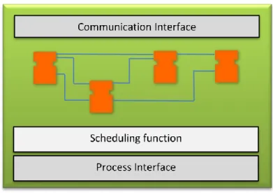
The Resource model resides in a device and every device can hold one or several resources. Applications are hosted by the resources, and each resource can host parts of, or complete, applications. The Resource can be regarded as a container for Function Block allocation and a functional unit that executes the Function Blocks. This is performed by accepting events and data from the Process and/or Communication interfaces, processing data and/or events, and returning data and/or events to the Process and/or Communication interfaces, as specified by the applications utilising the resource. The Process interface handles all requests concerning reading and writing the local devices´ inputs and outputs, while the Communication interface enables the exchange of data with Function Blocks in remote resources. These interfaces, in combination with an internal scheduling function, support the execution of the Function Block network within each resource.
Figure 3. IEC 61499 Resource model
(Figure used with the permission from Magnus Holm)
The applications which reside in a resource, local applications or separate parts of distributed applications, are made up of a set of interconnected Function Blocks. These Function Blocks are linked together, connected by their data and event connections into a network (Figure 3). The scheduling function controls the event flow within the Function Block network and the execution of the internal algorithms of each Function Block, to secure their correct order of execution. To facilitate communication with other resources, dedicated Service Interface-Function Blocks are used. The IEC 61499 standard defines several types of such Interface-Function Blocks.
1.1.2.2.4 The Application model
The IEC 61499 standard defines an application as a network of interconnected Function Blocks, linked together by their event and data connections. In practice, an application is the composition of a set of Function Blocks into a network required to control a specific process, system, or task, e.g. a separate machine, an automatic assembly cell or a complete production system. The overall functionality of an application can be divided into distributed sub-applications, each holding a separate part of the functionality of the application. As such, an application can either be downloaded into a single resource or split between several resources and multiple devices.
1.1.2.2.5 The Function Block model
The Function Block model is the lowest level of the IEC 61499 architecture and the formal descriptions of the data structure and the embedded algorithms of these Function Blocks are the core of the standard. In IEC 61499 several forms of Function Blocks are defined, each with a dedicated function and purpose. The main Function Block features (Figure 4) can be summarised as follows (Lewis, 2001):
Each Function Block type has a type name and a unique instance name. These should always be shown when the Function Block is graphically represented.
Each Function Block has a set of event inputs, receiving events from other Function Blocks through event connections.
Each Function Block has one or more event outputs, to pass on events to other Function Blocks.
Each Function Block has a set of data inputs, allowing data values to be received from other Function Blocks,
Each Function Block has a set of data outputs, allowing data values produced within the Function Block to be passed on to other Function Blocks,
Each Function Block has a set of internal variables to retain data between algorithm invocations,
The behaviour of a Function Block is defined by its internal algorithms and Execution Control Chart (finite state information). Using different Function Block states, various strategies can be used to define which algorithm to execute in response to particular events.
Figure 4. IEC 61499 Function Block model
(Figure used with the permission from Magnus Holm)
The structure and composition of the Execution Control Chart define the behaviour of the Function Block, by describing the relations for how the internal algorithms are triggered. When input events are received, the Execution Control Chart initiates the algorithm execution which, depending on the data input values and the internal variables, generates new data output values and an associated output event. The capabilities of the hosting resource, i.e. scheduling, communication and process mapping, support the various processes for Function Block execution. The Function Block execution follows the numbered sequence in Figure 4, and is described below:
1. Incoming values from other Function Blocks or from the controlled process are available at the data inputs.
EI_1 EI_2 EO_1 EO_2 DI_1 DI_2 DO_1 DO_2 Internal variables
AlgorithmsAlgorithmsAlgorithms Algorithms Execution Control Chart
Resource capabilities
(scheduling, communications and process mapping) 1 2 3 4 6 7 5 8 Instance name Type name
2. An incoming event from another Function Block or from the controlled process declares the availability of new data input values.
3. The Execution Control Chart changes state according to its transition conditions, and signals to the resource’s scheduler to execute the appropriate algorithm.
4. The execution of the selected algorithm is started.
5. The algorithm processes input values, and in some cases also internal variables, to create new output values which are written to the data outputs.
6. After algorithm execution completion, the resource scheduler is notified that output values are available.
7. The resource scheduler signals the Execution Control Chart to generate an output event.
8. An output event is created by the Execution Control Chart to announce the availability of new output data. This output event is a signal to other linked Function Blocks that they can now use output values generated by this Function Block.
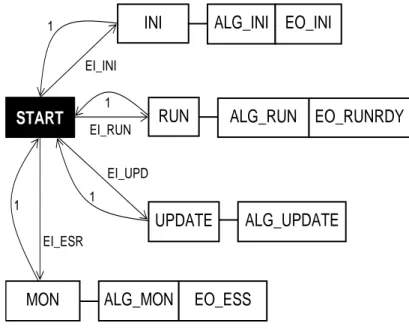
Below is an example of the behaviour and functionality of an Execution Control Chart, which is governed by transition conditions. The Basic Function Block in Figure 6 has four states, which can also be seen in its Execution Control Chart in Figure 5: START, INIT, RUN and UPDATE. Each of these states, except for START, has got an action (ALG_X) and an output event associated to it (EO_Y). When a state becomes active it will perform its action and then set the associated output event. Only one state can be active at a time and at start-up the START state is active. When an input event arrives, the transition conditions determines which state will become active. The transition conditions can be seen next to the arrows connecting the states of the Execution Control Chart in Figure 5. The returning event “1” indicates that the state transition condition is true, leading the system back to START state after completion of the actions in any of the other states.
This is the behaviour when an event arrives at EI_2:
Active state is changed from START to RUN since the transition condition EI_2 is true. The associated action is performed, executing algorithm ALG_2 and updating the
data outputs and internal variables.
Active state is returned to START since state transition condition is true (“1”).
The Function Block then remains idle to the next input event is received. If the event EI_1 is triggered, there are two possible behavioural alternatives. If the data input DI_1 = 0, the transition condition for the state INIT is true, but if DI_1 = 1, the transition condition for the state UPDATE is true. After executing the related algorithms and triggering event outputs of the selected state, the active state of the Execution Control Chart is once again set to the START state.
Figure 5. Execution Control Chart
(Figure used with the permission from Magnus Holm)
The IEC 61499 standard defines three different forms of FBs for creating functionality: 1. Basic Function Blocks – For low level atomic control functionality. Represents reusable functionality. A Basic Function Block (Figure 6) can only be executed in a single resource. 2. Composite Function Blocks – For creating higher levels of control functionality or complex control applications through a network aggregation of several Basic and/or lower level Composite Function Blocks into one. A Composite Function Block (Figure 6) does not have an Execution Control Chart or internal variables, and cannot be distributed over several devices or resources.
INIT ALG_1
UPDATE ALG_3
RUN ALG_2
START EI_1 & DI_1=0
EI_1 & DI_1=1
EI_2 1 1 1 EO_1
EO_2
EO_23. Sub-applications – A special form of a Composite Function Block for providing a reusable functionality of an application that can be distributed. A sub-application may constitute a decomposition of another, more complex sub-application or application. A sub-application cannot be executed on its own.
Figure 6. Basic Function Block (left) Composite Function Block (right). (Figure used with the permission from Magnus Holm)
A Basic Function Block is graphically made up of a head on top and a body beneath, as shown in Figure 6. The head captures the dynamic behaviour by receiving event inputs (EI) and producing event outputs (EO), while the body captures the functionality by receiving data inputs and generating data outputs.
Basic Function Blocks, Composite Function Blocks and Sub-applications can all be combined in a distributed Function Block network to arrange complex control applications. Their event and data interfaces will then be interconnected in a network of Function Blocks to control the propagation of different signals through the Function Block control network, for the fulfilment of the desired functionality of the application. The flow of events and data are realised in the network where one Function Block’s outputs of events and data are connected to other Function Blocks’ event and data inputs. The events and data signals will propagate this way through the Function Block network to fulfill the functionality of the control application. Event-driven Function Blocks thus allow the dynamic creation of manufacturing
Composite Function Block
EI_1 EI_2 EO_1 EO_2 DI_1 DI_2 DO_1 DO_2
Basic Function Block
Internal variabels AlgorithmsAlgorithmsAlgorithms
Algorithms
INIT UPDATE RUN
equipment control code, adapted to the actual shop floor conditions as it may be based on monitored real-time information.
1.1.2.3 IEC 61499 Applications
Research about the use and implementation of event-driven Function Blocks in different applications has been ongoing for a while, at least since the late 1990s. Literature reviews show that a variety of approaches using such Function Blocks have been proposed. However, even though the first version of the IEC 61499 standard was published in 2005, it will still be some years before it will be as widely adopted by the manufacturing industry as IEC 61131 (Strömman, Sierla, & Koskinen, 2005; Thramboulidis, 2007, 2009). It seems that the majority of IEC 61499 applications are limited to low-level process control for PLCs, which are not able to handle issues of adaptivity and uncertainty regarding process planning and execution control for complex machining or robotic operations in high-level manufacturing systems. A rather common Function Block application is the system design of autonomous distributed systems with intelligent control components. Early research on using Function Blocks describes holonic control (Lihui Wang, Brennan, Balasubramanian, & Norrie, 2001). Next-generation manufacturing systems will require agility, flexibility and fault-tolerance and these requirements can be satisfied by the emerging event-driven Function Block approach and its real-time control architecture for distributed control. Other examples of how IEC 61499 has been studied and discussed in the research literature are: an automatic verification of industrial control systems based on function block technology (Völker & Krämer, 2002), the development of an architecture for Function Block-oriented engineering support systems (Thramboulidis & Tranoris, 2001) and reconfigurable concurrent Function Block models and their implementations using real-time Java (Brennan, Zhang, Xu, & Norrie, 2002).
Research on implementations of IEC 61499 in process control systems are also found. The implementation of a real-time distributed control model using a Java-based platform is introduced by (Olsen, Wang, Ramirez-Serrano, & Brennan, 2005), where a control application is distributed across two devices, supported by a MANAGER Function Block, able of providing management services for devices. Real-time execution of IEC 61499 applications, describing the execution elements within a device and different scheduling and implementation approaches is presented by (Zoitl, Grabmair, Auinger, & Sunder, 2005), as well as critique against and solutions for, ambiguities concerning execution in the standard, leading to
different execution behaviour of elements on different control devices, by (Strasser, Zoitl, Christensen, & Sünder, 2011). The development, implementation and use of an IEC 61499 Function Block library for embedded closed-loop control is presented and demonstrated by (Strasser, Auinger, & Zoitl, 2004) on a real experiment: the control of a challenging seesaw problem.
Targeting the issue of manufacturing equipment control, various applications for e.g. CNC-machines and robots have been described. An open, layered CNC-FB architecture, simplifying the design of CNC machine controllers, is demonstrated by (Minhat, Vyatkin, Xu, Wong, & Al-Bayaa, 2009; Minhat, Xu, & Vyatkin, 2009). The architecture is based on STEP-NC (STandard for the Exchange of Product model data - for Numerical Control) (ISO, 2007) as the input data model and IEC 61499 as its development platform. The STEP-NC model provides data on the machining operation to be executed. A prototype system with a PC controlled 3-axis CNC vertical milling machine has been used to test the proposed architecture, and to prove that Function Block technology can be used for the development of open and distributed CNC systems. The actual control has been achieved by interfacing the three stepper motors of the machine through the parallel port of the PC, through an EMC controller and through a motor control unit that drives the motors. With this setup, only a signal for direction and a single pulse are needed to move the motors one step in any direction. A Composite-Function Block controls the motors by generating an output sequence on the parallel port.
Targeting the absence of a CNC-controller that is able to directly execute STEP-NC models, an adaptable CNC system based on STEP-NC and Function Blocks was proposed (H. Wang, Xu, & Tedford, 2007). It addresses the issue of porting STEP-NC data to different CNC controllers, to enable a “Plug-and-Play” functionality. The objectives of this STEP-compliant CNC system with Function Blocks incorporated are: to make product data interchangeable, to enable information flow seamlessly and to have a system that is independent of CAD/CAM systems. In their “Plug-and-Play” mapping system, a STEP-NC encoder reads data from an STEP-NC supporting system and encodes it into Function Blocks. A Function Block mapping system is then used to translate the STEP-NC code into native CNC-machining G and M codes, which are executed by an executing sub-system. One advantage with this system is that the current CNC machine configurations do not have to be modified. From a controller perspective, machine specific G and M codes can still be used.
An enhanced STEP-NC compliant CNC controller is presented by X. Huang (2010). In order to adapt the controller to a reconfigurable environment, an extended STEP-NC data model describing machining data from the viewpoint of product family is applied, as well as the Function Block device element model of IEC 61499. The approach is demonstrated on a XY table and linear module in an FMS platform, controlled by a PC with a motion control card. In Doukas, Thramboulidis, and Koveos (2006) an approach applying IEC 61499 Function Blocks for robotic arm motion control is presented, using a PID-based control for issuing motion commands to the robot. The motion behaviour for different variable PID parameters and sampling periods are examined to prove the correctness of the design and the implementation of the control application. In a literature review (Vyatkin, 2011) focusing on how IEC 61499 can enable distributed and intelligent automation, the author concludes that the standard facilitates control systems which may be automatically generated directly from the design documentation using integrated design methodologies. This review also concludes that the standard´s benefits for design of control systems, compared to other technologies used for automation control, have been well proven by system integrators with experience of IEC 61499 implementations.
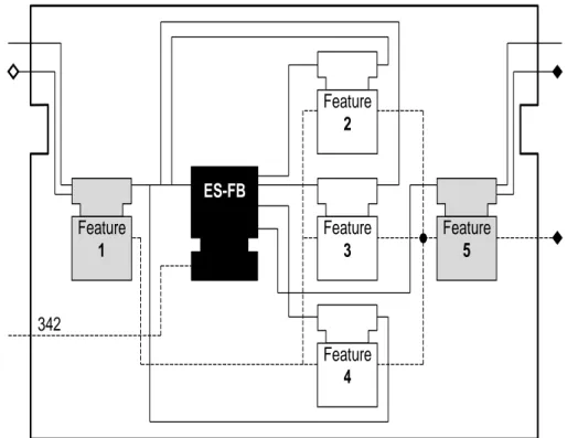
The concept of combining IEC 61499 Function Blocks and Manufacturing Features to realise event-driven adaptability for process planning and execution control for complex manufacturing tasks, such as robotic assembly operations, is described in Chapter 3.
1.1.3 Distributed Manufacturing
The increasing globalization is a trend which forces manufacturing industry of today to focus on more cost-effective manufacturing systems and collaboration within global supply chains and manufacturing networks. Cloud Manufacturing is evolving as a new manufacturing paradigm to match this trend, enabling the mutually advantageous sharing of resources, knowledge and information between distributed companies and manufacturing units. Combining recently emerged technologies, such as Internet of Things, Cloud Computing, Semantic Web, service-oriented technologies, virtualisation and advanced high-performance computing technologies, with advanced manufacturing models and information technologies, it provides a framework for collaboration within complex and critical tasks, such as manufacturing and design. This will lead to the flexible usage of different globally distributed, service-oriented manufacturing systems and resources, increasing the companies’ ability to successfully compete on a global marketplace.
One major manufacturing challenge for manufacturing companies to be competitive, identified in section 1.1.1 was:
- The ability to participate in distributed resource sharing and collaborative manufacturing activities.
This relates to the developing trend within the manufacturing shop floor domain of moving manufacturing activities into cloud environments, as scalable, on-demand and pay-per-usage cloud services, which is both timely and economically attractive. It is envisioned that companies in all sectors of manufacturing will be able to package their resources and know-hows in the Cloud, making them conveniently available for others. Resources, e.g. manufacturing software tools, applications, knowledge and fabrication capabilities and equipment, will then be made accessible to presumptive consumers on a worldwide basis. This will radically change traditional manufacturing, as borderless, distributed and collaborative manufacturing missions between volatile, best suited groups of partners will impose a multitude of advantages.
The evolving Cloud Manufacturing concept will increase opportunities for outsourcing and new joint ventures both locally and globally (X. Xu, 2012), but the level of complexity regarding manufacturing control will become significantly higher. Moving towards distributed manufacturing in new, collaborative and volatile partnerships will increase the importance of effective and dynamic planning, coordination and execution of manufacturing activities. Distributed Process Planning will be required for these multi-collaborative manufacturing environments, especially for those scenarios in which dynamically configured groups of dispersed resource providers are cooperating in manufacturing missions. Without an effective approach combining both planning, control and execution, based on both global and local conditions, the forecasted advantages of Cloud Manufacturing will be severely restricted (F. Tao, Zhang, Venkatesh, Luo, & Cheng, 2011).
Cloud Manufacturing is often related to, and compared with, other advanced networked manufacturing concepts, e.g. Networked, Internet-based, Distributed, and Grid Manufacturing (L. Zheng, Jiang, Qiao, & Xi, 2010; X.-l. Zheng, Chen, & Lu, 2005) (Parker, 2007; F. Tao, Hu, & Zhang, 2010). There are, however, some major differences. These networked concepts focus on a single manufacturing task and the integration of distributed resources for undertaking the task. They do not have a centralised operation management of the services, choice of different operation modes and embedded access to physical
manufacturing equipment, applications and capabilities, which are prerequisites for a seamless, stable and quality transaction of manufacturing resource services. Having little coordination between the resource service provider and the resource service consumer, these concepts are significantly less effective (X. Xu, 2012). In contrast to these concepts, Cloud Manufacturing also promises elasticity, flexibility and adaptability through the on-demand provisioning of manufacturing resources as services, enabling the fundamental and necessary features such as convenient scalability and pay-as-you-go of resources shared (J. T. Zhou, Yang, Wang, K., & Mo, 2011).
Cloud Manufacturing has been the focus for a great deal of research interest and suggested applications during recent years, by both industrial and academic communities, and many of its anticipated core virtues and enabling technologies have been described. After surveying a vast array of available publications, a comprehensive review of issues related to adaptive and distributed control of manufacturing equipment within Cloud Manufacturing is presented in Chapter 2.
1.1.4 Semantic Web and ontology technologies
Product and manufacturing resource data is often handled by heterogeneous information systems and stored in different systems at the facilities of manufacturing resource providers and those consumers requesting the performing of a manufacturing task. Using an ontology-based approach, the contents of different data sources can be retrieved and represented in a semantically uniform description. With ontology extraction, information regarding resources or products can be structured and formalised into local ontologies. In addition, through the use of semantic augmentation and querying, as well as matching to global manufacturing ontologies, new information may be inferred.
To support the Function Block-based cloud control approach described in the Chapter 6, enabling the matching of manufacturing task requests with provider resources’ capabilities, reference information models of these are required. Building on the concept of product Manufacturing Features, a unified information framework describing manufacturing tasks and manufacturing resources’ capabilities from a shared product feature perspective is outlined in Chapter 3. For description of product manufacturing tasks, a feature-enriched product data model is presented, and for manufacturing resources’ capabilities, a feature-level capability model. Together, these two models facilitate manufacturing resource discovery, and the matching of manufacturing resources to requested tasks. For structured