I
Standard vs. revolutionary sealing:
Karim Alamien
An investigative thesis on two methods of conceptual designing with
regards to the root causes of failure mode in raw mill 7.
Mechanical Engineering, Blekinge Institute of Technology, 371 79 Karlskrona, Sweden Master of science in Mechanical Engineering
III
Preface
This thesis is submitted to the Faculty of Engineering at Blekinge Institute of Technology in fulfillment of the requirements for the degree of Master of Science in Mechanical
Engineering. The thesis was done in cooperation with Cementa AB in Slite, Gotland.
I, Karim Alamien, declare that I am the sole author of this thesis and that I have not used any sources other than those listed in the bibliography and identified as references. I further declare that I have not submitted this thesis at any other institution to obtain a degree. Firstly, I would like to thank my supervisors Ansel Berghuvud, Magnus Pettersson and Henrik Stenegärd for their excellent guidance throughout this project.
I would also like to thank my brother Hassan, my sister in law Pamela and their kids Elias and Alicia for their warm hospitality and support during this project.
Lastly, I would like to thank my mother and father for their persistent nagging and counseling and without whom I would not be where I am today.
I hope you enjoy your reading.
Contact information: Author: Karim Alamien Karimalamien@live.se University advisor: Ansel Berghuvud
Department of Mechanical Engineering
Faculty of Engineering
Blekinge Institute of Technology SE-371 79 Karlskrona, Sweden
Internet : www.bth.se
Phone : +46 455 38 50 00 Fax : +46 455 38 50 57
V
Abstract
The grinding rollers of raw mill 7 operate in very harsh conditions and, because of this, suffer from excessive failure mode due to lip seal deterioration. Foreign material penetrates the deteriorated lip seal and enters the bearings resulting in bearing failure. Failure mode brings about high maintenance costs for the cement-producing company Cementa AB. This thesis aims to accomplish two things. 1- Hypothesize a set of root causes for failure mode and link them to existing literature studies to determine what actions should be taken to prevent or at least postpone failure mode. 2- Generate several new conceptual designs for the sealing mechanism by either creating a revolutionary sealing design or taking inspiration from standard seals currently on the market. The generated concepts aim to provide Cementa AB with a new perspective as well as mitigate some or all the root causes for failure mode if implemented. The hypothesized root causes for failure mode are categorized through the creation of a problem tree and are defined as lip seal failure, lubricative pressure and contamination, tribologically improper friction, vibration, and finally very harsh conditions that are indigenous to raw mills in general and that are seemingly incompatible with the current sealing mechanism. Revolutionary concepts are brainstormed entirely from an experimental perspective, while standard concepts are inspired by established sealing technology on the market. Both alternatives are then conceptually adapted to the grinding roller of raw mill 7 and, with inaccurate scaling, 3D modelled with the aid of Autodesk Inventor.
7 concepts, revolutionary and standard combined, are generated as a result. The revolutionary concepts have been deemed non-viable due to the limited timeframe and scope of the thesis. Instead, the selected seal for the upgrade is a labyrinth seal, which is a non-contact standard seal that has the potential to mitigate many of the root causes for failure mode. The literature studies on the hypothesized root causes also indicate that there are actions that could postpone failure mode should Cementa AB chose to retain the original sealing mechanism for a longer period. Keywords: Failure mode Mechanical seal Tribology Raw mill Cement
VI
Sammanfattning
Valsarna i råkvarn 7 arbetar under mycket tuffa förhållanden och på grund av detta lider maskinen av en överdriven mängd haverier till följd av läpptätnings försämring. Främmande material tränger igenom den försämrade tätningen och kommer in i lagren vilket resulterar i lagerhaveri. Detta medför höga underhållskostnader för det cementproducerande företaget Cementa AB. Denna avhandling syftar till att åstadkomma två saker. 1-Hypotesera en uppsättning av grundorsaker till lagerhaveri och länka dem till befintliga litteraturstudier för att avgöra vilka åtgärder som kan vidtas för att förhindra eller åtminstone skjuta upp lagerhaveri. 2-Generera flera nya konceptuella konstruktioner för tätningsmekanismen genom att antingen skapa en revolutionerande tätningsdesign eller hämta inspiration från standardtätningar. De genererade koncepten syftar till att ge Cementa AB ett nytt perspektiv såväl som att mildra några eller alla grundorsaker till lagerhaveri om de implementeras.
De hypotiserade orsakerna till lagerhaveri kategoriseras genom skapandet av ett problemträd och definieras som trasig läpptätning, smörjningstryck och förorening, tribologiskt felaktig friktion, vibrationer och slutligen tuffa förhållanden som är inhemska för råkvarn generellt. Revolutionära koncept är brainstormade helt ur ett experimentellt perspektiv medan standardkoncept är inspirerade av etablerad tätningsteknik på marknaden. Båda alternativen är sedan konceptuellt anpassade till valsen i råkvarn 7 och, med oegentlig skalning, 3D-modellerad med hjälp av Autodesk Inventor.
7 koncept, revolutionerande och standard kombinerat, genereras som resultat. De revolutionära koncepten har bedömts vara icke-livskraftiga på grund av avhandlingens begränsade tidsram och omfattning. Istället är den valda tätningen för uppgraderingen en labyrinttätning som är en icke-kontakt standardtätning som har potential att mildra många av orsakerna till lagerhaveri. Litteraturstudierna om de hypotiserade grundorsakerna tyder också på att det finns åtgärder som kan skjuta upp lagerhaveri om Cementa AB väljer att behålla den ursprungliga tätningsmekanismen under en längre period.
Nyckelord: Lagerhaveri Mekanisk tätning Tribologi Råkvarn Cement
VII
Table of contents
1 Introduction ...1
1.1 Background ...2
1.1.1 Cementa AB ...2
1.1.2 General Cement-production process ...2
1.1.3 Raw mill 7 ...4
1.1.4 Raw mill 7th grinding roller ...7
1.2 Main problem statement ... 10
1.2.1 Bearing failure: The main problem ... 10
1.2.2 Subsequent problems ... 12
1.3 Scope of the thesis ... 13
1.4 Objectives ... 14
1.5 Values of a potential upgrade ... 14
1.6 Thesis questions ... 14
1.7 Thesis outline ... 15
2 Problem tree ... 16
2.1 Lip seal failure ... 17
2.2 Harsh Environment... 18
2.3 Tribology ... 19
2.4 Vibration ... 23
3 Process for redesigning the sealing mechanism ... 24
3.1 Data collection ... 24
3.2 Modelling raw mill 7th original Grinding roller ... 25
3.3 Inspiration from raw mill 8 ... 26
3.4 Inspiration from other companies ... 26
3.5 Examples of standard seals ... 27
3.5.1 Rotary shaft seals ... 27
3.5.2 Dynamic rotary gland seals with O-rings ... 27
3.5.3 Non-contact seal - labyrinth seal ... 32
3.6 Concept generating and modelling ... 33
3.6.1 Concept criteria ... 34
3.6.2 Idea generating process ... 34
3.6.3 3D modelling process ... 35
4 Results ... 36
VIII 4.2 Concept 2 ... 37 4.3 Concept 3 ... 38 4.4 Concept 4 ... 39 4.5 Concept 5 ... 40 4.6 Concept 6 ... 41 4.7 Concept 7 ... 42
5 Analyses of the concepts ... 43
5.1 Concept 1 ... 43 5.2 Concept 2 ... 43 5.3 Concept 3 ... 44 5.4 Concept 4 ... 44 5.5 Concept 5 ... 45 5.6 Concept 6 ... 45 5.7 Concept 7 ... 45 6 Discussion ... 46
6.1 Lip seal failure ... 46
6.2 Tribology ... 47
6.3 Harsh environment ... 48
6.4 Vibration ... 49
6.5 Bad overall sealing construction ... 50
6.6 Failed concepts ... 51
6.7 Canceled research ... 52
6.8 Revolutionary vs. standard ... 53
7 Conclusions ... 54
7.1 Actions that could potentially aid in postponing failure mode ... 54
7.2 Suggesting a concept for Cementa AB ... 55
8 Future work ... 56 Bibliography ... 57 Appendices ... 60 8.1 Appendix 1 ... 60 8.2 Appendix 2 ... 64 8.3 Appendix 3 ... 71
1
1
I
NTRODUCTION
It is tough to imagine a world without concrete. Concrete might be one of the essential materials in the process of building modern societies sustainable infrastructure. A key element in concrete is cement, and it is the cohesive ingredient for making robust concrete. This thesis is written in cooperation with Cementa AB. The studies and work were conducted on-site in the factory with the privilege of working during the annual maintenance stop of the factory. This created a one of a kind opportunity to mentally and physically dive into the subject and the machines in question while they were on standby. Much of the information about the topics presented in the thesis was gathered through interviews with managers and workers in the factory. As such, some of the information in the thesis belongs to manual interviewing. One example is the general cement-production process. Throughout the thesis, it is important to keep in mind that the expressions failure mode and bearing failure are referring to the same problem. Many of the figures and pictures in the thesis were apprehended through manual photography during the maintenance stop.
2
1.1 Background
1.1.1 Cementa AB
Cementa AB is one of the leading cement-producing companies in Sweden and in the world. The company is part of the international building-material group, HeidelbergCement, and has approximately 58 000 coworkers worldwide. Cementa AB has three cement plants in Sweden. They are located in Slite, Skövde, and Degerhamn. These plants are strategically placed near available limestone quarries. Limestone is one of the basic materials for producing cement [1]. This thesis will mainly focus on the plant in Slite, Gotland.
1.1.2 General Cement-production process
To be able to appreciate the importance and weight of the subjects presented in this thesis, a basic understanding of the cement production process is necessary. Below is a relatively short, generalized step by step introduction to the process from start to finish. The information was apprehended through a series of interviews with managers and workers in the factory.
Mining:
Cementa AB produces about 2-million-ton cement annually. To support the production rate, a large quantity of raw materials in the form of limestone and marlstone is extracted from the underlying limestone bedrock in the proximity of the factory. It is estimated that about 3 million tons of limestone and marlstone is mined annually. Marlstone being of lesser calcium carbonate content, which is what gives the limestone it's signature white color. Extraction is done by drilling holes around the open cast mine and injecting liquid explosives. Every explosion releases about 20-70 000 tons of stone. The stone is then transported to a crushing facility.
Crushing:
Stone from the mines arrives to be crushed. Since the rocks are relatively homogeneous, it is enough to fragment them once. The crushing takes place in a hammer-crusher, which breaks the material into fist-sized stones with an estimate of 2200 tons per hour. The dimensions of the rocks are adjusted for the later milling part of the process. The stones are then transported to the storage facility near the factory.
Stone storage:
The stone warehouse has two main functions. Firstly, it acts as storage for the crushed stones that will be further transported to the next step of the process in the factory. Secondly, it acts as a mixing station of different raw materials used in the production.
Raw mill:
This step Is considered to be a crucial part of the process for ensuring the quality of the cement production. Limestone and marlstone are transported separately via conveyers into a stone allocation tower where the material is stored in pockets, still separate at this point. The content is then fed into raw mills together with different essential additives such as quarts-sand and iron-ore. The purpose of the raw mill is to mill the stones into a fine raw flour. The flour is then transported to silos.
3 Raw flour silos:
The silos also act as a temporary storage space for the fine flour. However, in the silos, the raw meal is continuously mixed through homogenizing. Air is blown from below the silos, which turn the meal into an almost fluid state. This makes the mixing process more manageable and increases the quality of the flour. Homogenizing is also especially important to achieve a good combustion process in the upcoming furnace.
Cyclone system:
Before feeding the furnace with the material, the raw flour has to get preheated. This takes place in one of the cyclone towers, which connects to the rotary kilns. The meal is transported to the top of the tower, where it drops down stepwise through cyclone chambers. Usually, there are four steps or chambers. Hot gas is blown from the furnace upwards through the system, with the hottest chamber being the closest to ground level and the furnace.
Rotary furnace:
Once the flour is preheated, it is fed into the rotary furnace, which rotates with about 1,5-3 revolutions per minute. There are two of them in the factory, one 70 meters long and the other 80 meters. Both are slightly slanted to allow the material to travel along its axis. The furnace's inner temperature is about 1450 degrees Celsius, which is the optimum temperature for converting the raw flour into clinker. At the end of the furnace, the clinker is dropped into a clinker cooler.
Clinker cooler:
After the furnace, the clinker has to rapidly decrease in temperature to stop all chemical processes that occur during the clinker formation from resuming. When the clinker leaves the cooler, it has a temperature of about 100 degrees Celsius. It is then transported to clinker silos.
Clinker silos:
Storing the clinker in the right conditions is very important since it is easily damaged by moisture. This takes place in the clinker silos.
Cement mill:
Through the combustion process, the raw flour has converted into clinker shaped like small balls. To achieve the final product, another milling process of the clinker is required. This takes place in a cement mill. Clinker and other additives that help to get the right attributes in the different cement qualities are fed into the mill—the finer the flour, the better the reactions when introducing water for creating concrete.
4
1.1.3 Raw mill 7
There used to be three raw mills in the factory, but today only two are operational. Raw mill 7 and 8. Raw mill 8 is a Polysius mill while raw mill 7 is a Loesche mill. The Polysius mill is much larger and can handle more substantial quantities of raw material with a higher production rate. For this thesis, the focus will be on the Loesche mill, raw mill 7. But for comparison's sake, the size difference of the grinding rollers for each raw mill is shown in figures 1 and 2. There is a substantial difference in size between the two. Also, the design is different, meaning that the components within are various as well.
The internal process of raw mill 7 starts when the raw material in the form of fist-sized stones are fed into the mill by a rotary feeder shown in figure 3.
Figure 1. Raw mill 7 grinding roller. Figure 2. Raw mill 8 grinding roller.
5 The stones then fall down to the center of the milling table, as shown in figure 4. In figure 4, the milling table isn’t complete due to it being under maintenance. The outer layer of the table has been stripped for renovation. Before falling, the material is subjected to a powerful
magnet that separates unwanted objects, mainly metals, from the raw material as not to
damage the components within the mill. The milling table spins around its own axis by the aid of the motor below the raw mill and creates a centrifugal force that drives the raw material outwards toward the edge of the table where the grinding rollers operate. What makes the grinding rollers spin is the contact of raw material in between the rollers and the milling table. As such, the rollers do not need a motor and instead rely on the spinning force of the table.
There are two rollers inside the mill on opposite sides and are hydro-pneumatically spring-loaded since grinding is done by application of compressive force through the “holder” shown in figure 5. The rollers are mounted on the holders and are folded into the raw mill, as shown in figures 5 and 6.
Figure 7. Grinding roller holder (folded in).
Figure 8. Grinding roller holder (folded out).
6 The rollers also spin around their own axis, and the material is ground in a material bed between the grinding track and rollers. The purpose of the gap is to eliminate metal on metal friction. Once ground, the material is once again subjected to the centrifugal force of the milling table and is driven further outwards toward the surrounding gas entries shown at the edge of the milling table in figure 4. Hot gas from the rotary furnace, as well as the cyclone system, is driven upwards through the entries around the milling table. This creates sort of a hurricane-like environment inside the raw mill. The stream of gas carries the ground material into a wind-sifter, also called classifier or separator shown in figures 9 and 10, where sufficiently ground fine flour passes through onto the next step of the process while not completely ground material is rejected. This material then falls into a return cone and afterward onto the milling table once again.
Another essential purpose of the hot gas is to draw moisture out from the raw material. To achieve this, the gas needs to be around 100-110 degrees Celsius [2].
Figure 11 illustrates all the mentioned relations within a raw mill and is a relatively accurate representation of raw mill 7 as well. Figure 12 shows the outside structure of the actual raw mill 7.
Figure 10. Wind-sifter.
Figure 11. Typical roller mill layout. From [24]. Figure 12. Structure of raw mill 7 from the outside.
7
1.1.4 Raw mill 7
thgrinding roller
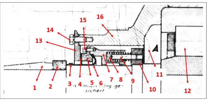
The design of raw mill 7 and its inner structure as well as the inner structure of the grinding rollers and sealing mechanism date back to the year 1970 when the machine was first commissioned [3]. Figure 13 shows a cross-section of the grinding roller, and the design has mostly stayed the same throughout the years, with spare parts being swapped during renovations and when needed.
For this thesis, the primary sealing area of the grinding roller shown in figure 14 will be the focus. The sealing mechanism is situated, as shown in Figure 15.
Figure 14. Cross section of the roller sealing area.
Figure 13. Cross section of raw mill 7th grinding roller.
8 Rotating and fixed components:
Sealing components:
Below is a list describing the function and purpose for each component shown in figure 17, within and in the vicinity of the sealing mechanism. All components, replacements and spare parts are made by and ordered from the original Loesche supplier. The terms used to describe each component are not the precise terms used by the supplier. The below list does not have to be read in any particular order.
1. Outer ring 1. The last ring mounted before mounting the grinding roller in the holder. The end of the mounting process mostly covers it. It acts as a layer between shaft and holder to hold the roller in place.
2. Outer ring 2. This outer ring is still visible once the grinding roller is mounted in the holder. It contributes to further sealing by protecting the lip seal (6) from the side in which it is situated. It also reduces the space in which foreign material may infiltrate.
Figure 17. Sealing mechanism component identification.
9 3. Seal clamp.This clamp fastens the lip seal (6) in place.
4. Rubber seal. This is a piece of rubber placed in between the sealing ring (13) and the pinching ring (5) for additional sealing.
5. Pinching ring.This ring and the spring housing (7) pinch the lip seal (6) in place. It is lifted some distance above the shaft level to allow the lip seal to move under it.
6. Lip seal. The lip seal is an elastomeric ring of rubber and is pinched between the pinching ring (5) and spring housing (7). It then continued under the sealing ring (13) and clamped by the seal clamp (3).
7. Spring housing. This component contributes to the pinching process and houses the sealing spring (8).
8. Sealing-spring.The purpose of the spring is to give the lip seal (6) a degree of freedom to move. This is to not cause too high stress on the lip seal during axial and radial movement of the mechanism, which could cause premature wear.
9. Spring rod.The sealing spring is mounted on it. 10. Spring rod housing.
11. Free space.
12. Cylindrical roller bearing.
13. Sealing ring. This ring is the outer protection of the sealing mechanism. It is also lifted some distance to allow the lip seal (6) to move under it. However, the sealing ring does come in contact with the lip seal, which is the primary sealing action through constant friction.
14. Sealing-ring bolt. The sealing ring is bolted to the outer lid, which is why it is among the rotary components, as shown in figure 16.
15. Pinching-bolt. 16. Outer lid.
To assemble and mount the grinding roller, a set of steps provided by the supplier are followed. These steps are presented in appendix 1 in Swedish. The steps act as a guide for the workers in the workshop when renovating the grinding roller during a maintenance stop.
10
1.2 Main problem statement
1.2.1 Bearing failure: The main problem
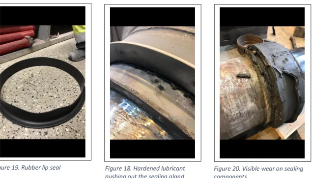
What allows the cylindrical grinding rollers in raw mill 7 to rotate freely in a given direction around their axis are the bearings within. These bearings are periodically lubricated sufficiently enough to allow for efficient rotation. To protect the bearings and the lubricant inside from invasive material, seals are put in place. The primary seal is a lip seal made of elastomeric rubber, as shown in figure 19.
The fundamental problem is that the chosen rubber lip seal deteriorates at a high rate. A big factor to this would have to be the fact that the lip seal operates in dry conditions for the majority of the running time. There exists little to no lubrication film between the rubber and outer sealing ring it is in contact with during rotation. When newly mounted, the grinding roller is packed with lubricating grease, as shown in appendix 2. Grease is then periodically and manually pumped through the shaft up into the bearing and out through the sealing mechanism. This creates a sort of positive pressure of lubrication that is meant to keep invasive material from entering. With this in mind, the lubricant does reach the space between the rubber seal and outer sealing ring due to the positive pressure. However, the high operating temperatures quickly dry out the immediate lubrication film, and the constant blowing of raw material hardens the lubricant to the point of almost a solid-state, and dry friction between the components occurs instead. This can visibly be seen in figure 18. Also, the wear on the lip seal is visible in figure 20.
The dry friction in conjunction with the seemingly unending harsh condition within the raw mill hastens deterioration. Furthermore, with the constant stress against the seal by lubricants, contaminated or otherwise, from within and among other factors, an endless stream of high-speed material from the outside in combination with high temperatures, the seals tend to give in and allow for unwanted materials to infiltrate the bearings they were meant to protect finally.
Figure 20. Visible wear on sealing components.
Figure 18. Hardened lubricant pushing out the sealing gland. Figure 19. Rubber lip seal
11 There are two routes in which invasive material can travel within the sealing mechanism to be able to reach the bearings. This is illustrated in figure 21.
Also, the lip seal has a thickness of barely a centimeter, which does not contribute to a longer lifecycle within these conditions. The invasive material then clogs the bearings by
contaminating and eventually hardening the grease-based lubricant, which in turn adds to the pressure on the seals as well as the bearings. It doesn’t take long for bearing failure to occur once this happens.
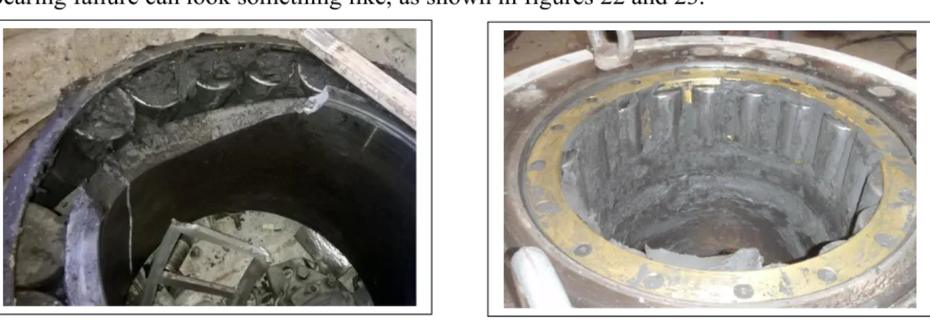
Bearing failure can look something like, as shown in figures 22 and 23.
The factory has made countless so-called “root cause failure analysis” or RCFA, which supports the fact of the excessive frequency of failure mode and the conclusion of poorly performing rubber seals as well as sub-optimal lubrication. Examples of RCFA can be reviewed under appendix 2.
Today, the best-case scenario is replacing the seals periodically before further infiltration of material. The worst-case scenario is reaching failure mode or bearing failure within an unplanned timeframe, and as mentioned, seal deterioration is a frequently appearing issue. With this in mind, one can assume that failure mode can occur due to foreseen as well as, as of yet, unforeseen factors, which is what this thesis will research upon.
Also, the bearings within the grinding roller were initially meant to be oil lubricated when the machine was set into commission and, in fact, was operated as such at first. The factory had run it that way for a while, but due to seal deterioration that caused the oil to leak out onto the raw material, the method was quickly changed to grease-based lubrication, which is the current
Figure 22. bearing failure (cracking). Figure 23. Bearing failure (clogging).
12 method today. The lubrication method works as intended when it is newly applied but encounters a range of problems, as previously mentioned. Because of the high viscosity of the grease, leakage was no longer an issue but proved itself to be a sort of double-edged sword in the long run due to the eventual hardening of the grease by invasive material.
1.2.2 Subsequent problems
Considering the crucial part that the raw mill plays in the production process, it is worth considering the subsequent problems of seal deterioration. Later on, in the methodology section, a problem-tree showcasing the cause and effects of failure mode will be presented with a more detailed study for each problem branch. But continuing on a range of problems arises in conjunction with seal deterioration.
First off, the inconvenience of having to maintain the grinding rollers by replacing the seals periodically. Of course, this can be considered a natural part of the sealing life cycle; however, when considering the consequences of unexpected or hastened seal deterioration, the problem becomes a lot more severe. Although the change of seals usually takes place during planned maintenance stops and has proven to be quite manageable but definitely not sustainable. This is why it is essential to have seals that at least hold up until the planned maintenance stop so that unnecessary stops in-between don’t have to happen. Secondly, replacing the seals at a high frequency has become the norm for raw mill 7, and it costs the factory a lot of money in the long run.
The inconvenience is furthered by having to pump grease onto the bearings manually. Too much pumping of grease onto the bearing can lead to over-saturation prone to overheating the bearing. And too little pumping of grease does not contribute to the desired positive pressure of lubricant to keep out invasive material. By introducing a better seal, oil lubrication could once again be implemented if so desired. There are many advantages to having an oil-circulation system. Monitoring the oil level, temperature, and pressure are some of the benefits as well as not having to inject the lubrication manually, which saves valuable time and effort that can be put elsewhere.
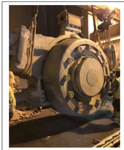
When looking at further subsequent problems of bearing failure due to seal deterioration, the consequences become a lot more severe. The raw mill has to stop to be able to replace the failed components completely. To do this, the whole grinding roller has to be extracted. This process can take up to 5 or 6 days to complete, which causes production to halt to some extent. Usually, however, a spare roller has been renovated for such a time and can with relative haste be a replacement to the faulty one in commission. Of course, it can also be argued that the toll on the overall production isn’t as detrimental as one could assume because of the continuously filled raw material silos that the raw flour accumulates in after the raw mill. However, in the case that the silo-usage isn’t maximized at the time of the failure, then the consequences may become more severe. It has become quite reasonable to expect failure mode at some point due to the high frequency that it occurs, but the fact remains that it is challenging to foresee actual failure timing because of the unreliability of the current sealing method. The risk then becomes greater and should be mitigated as soon as possible.
13
1.3 Scope of the thesis
This thesis will focus on two separate aspects: a theoretical study phase and a practical conceptual designing phase.
The first aspect is in the form of a study and is part of the chosen methodology for the thesis. The study is in the way of an identification and examination process of the causes for failure mode within the grinding rollers of raw mill 7. The problem statement section of the thesis has already touched on some of the general causations extracted from the point of view of the workers that handle the maintenance of the grinding rollers in the factory. Identification of causes will be made through the creation of a problem tree. The problem tree will be based on the hypothesis surrounding the most likely reasons that failure mode occurs. This will also be in combination with the already established reasons presented in the problem statement section. Each problem hypothesis branch in the problem tree will be researched on the world wide web for the aim of confirming that the hypothesized problems in the tree are, in fact, contributing factors for failure mode. The problem branches will then be related to external literature studies for further confirmation. The purpose of this, first of two aspects of the thesis, is to give Cementa AB a relatively short basis to understand and potentially improve upon the problematic factors of failure mode. The studies conducted are not meant to yield any specific results but are intended to be discussed in the discussion section to further support the notion of a need for a significant upgrade to the sealing mechanism in the grinding roller of raw mill 7.
The upgrade of the sealing mechanism is the second of the primary aspects of the thesis and is the practical approach meant to yield the thesis results. This will be done through conceptual designing and modelling, which falls in line with Cementa ABs' expectations for the project. Namely, to present a number of concepts, either inspired or revolutionary, for the sealing mechanism. The freedom to generate any type of conceptual design has been given. The purpose of this is not necessarily to implement one of the generated concepts but to provide a new perspective on what could potentially be a good idea by an up-and-coming engineer. Cementa AB already has already acquired suggestions regarding new sealing mechanisms from external companies but is not inclined to share these as the purpose is, as mentioned, to provide a new perspective. It is, therefore, essential to once again emphasize the fact that the concepts that are eventually generated in the thesis aren’t meant to be complete with regards to dimensional accuracy, scale, or implementational readiness. This includes both ideas inspired by established sealing standards and revolutionary concepts. Cementa AB has also forbidden contact with Loesche, the original supplier of the raw mill, since they hold one or more of the already suggested upgrades. All data concerning the dimensions of the grinding roller is gathered from the internal system of the factory. The bearings of the grinding roller will not be altered in any way. The generated concepts will assume that the lubricant used in the sealing mechanism is grease-based and will, as such, not be concerned with optimizations regarding the choice of lubricant. When generating the concepts, if chosen to implement, a sealing rubber used in a rubber-based concept will be assumed to be able to take on any shape demanded by the concept. This means that special orders of sealing rubber from external companies are a valid approach. Also, calculations on costs and savings for the potential upgrades will not be conducted.
14 Furthermore, catering to the conducted study and the concept generating towards Cementa AB does not mean that the concepts aren’t applicable in other factories that have an operating Loesche raw mill as well. The conceptual data may then also be compared to other rollers or machines around the world that have similar or identical problems and, through this, aid them in the implementation of a more sustainable solution. They may then even be adopted in other types of rotary machines that have a need for a better performing sealing mechanism, other than raw mills provided that the potential solution is compatible.
1.4 Objectives
• Define a hypothesized problem tree and, through it, research into, present, and discuss existing information and studies linked to the hypothesized potential causes for bearing failure.
• Generate several conceptual designs to the sealing mechanism in raw mill 7th grinding roller with the aid of either inspiration from standard seals or revolutionary thinking. • Conclude by suggesting at least one of the generated concepts and briefly explain how
the concept mitigates the discussed causes for bearing failure.
• Conclude by suggesting lifecycle extending measures, should Cementa AB chose to keep the original sealing mechanism for a more extended period.
1.5 Values of a potential upgrade
• Reduces maintenance costs • Reduces spare-part usage
• Decreases time consumption during a maintenance shutdown • Decreases the frequency of production stop due to failure mode. • Decreases the overall risk of production stop due to failure mode. • Continuous production rate
1.6 Thesis questions
• Can hypothesized root causes for failure mode within raw mill 7, related, and compared to literature studies concerning each contributing factor, help determine actions that could prevent or at least postpone total failure?
• Can upgrades through revolutionary conceptual designing with respect to the conducted literature studies on failure mode within raw mill 7, be as effective as selecting an already performance-tested and verified standard design?
15
1.7 Thesis outline
Cement is a critical component in concrete, which is the cornerstone of modern society's infrastructure. Cement is produced through a series of production steps. One of those steps is the crushing of limestone into a raw flour. The machine responsible for crushing is the raw mill. For this thesis, the focus will be on the company Cementa AB, raw mill 7. Within the raw mill, the crushing is done by feeding fist-sized limestones to a milling table where two grinding rollers crush the stone between themselves and the table. The grinding rollers rotate around their axis with the aid of roller bearings within. Roller bearings need to be sufficiently lubricated to function properly, which is why seals are put in place to protect the lubricant and the bearings from contamination that could lead to failure mode. The grinding rollers use a traditional rotational lip seal as a sealing mechanism. The conditions inside raw mill 7 are harsh with high temperatures. These conditions lead to premature lip seal deteriorating, which in turn allows for foreign raw material to penetrate its way into the bearings resulting in failure mode.
One of the thesis objectives is to hypothesize further potential causes for failure mode and relate them to literature reviews to either confirm or contradict them. The hypotheses, in conjunction with the literature studies, will then aim to determine what actions could be taken to prevent or postpone failure mode. The hypotheses are made through the creation of a problem tree. This methodology is suitable for the study since the subject of bearing failure and seal deteriorating is one that has been studied for almost a century with ongoing studies. Hypothesizing causes for failure mode could provide a new perspective that might contribute to the collective worldwide study on the matter.
Further thesis objectives are to generate conceptual designs with the aid of 3D modelling for a new sealing mechanism better equipped to handle the conditions within the raw mill. The concepts can either be revolutionary or they can be standard. Part of the objective is to determine if revolutionary designs can be as effective as selecting from a range of standard designs, and another part is to relate the concluded selected conceptual design to the literature studies on bearing failure by pointing out how the new concept mitigates the main problem, failure mode. This methodology is suitable for the thesis since it aligns with the expectations of Cementa AB.
The problem tree was accurately hypothesized, with many literature studies existing for each problem branch. Unfortunately, none of the hypotheses were revolutionary, and while failure mode prevention was too much to hope for, the gathered information has many implications on how Cementa AB could try and at least postpone failure mode should the original sealing mechanism continue operating. Seven concepts, revolutionary and standard-inspired combined, have been generated and modelled. Revolutionary designing, in conjunction with the limited timeframe of the thesis, resulted in non-viable concepts that, while potential exists, are in need of further development. Instead, a standard design was chosen, the labyrinth seal, which is a non-contact seal that, in theory, could mitigate many or all of the causes for failure mode within raw mill 7. For future work, contact with labyrinth seal suppliers will be the main priority in order to confirm combability and operability.
16
2
P
ROBLEM TREE
One of the main steps of methodology for this project is creating the problem tree above. The problem tree illustrates the root cause and effects of failure mode based on educated hypotheses in combination with field studies in the factory where countless workers have been interviewed. The effects are marked in green and root causes in blue.
The root causes were formulated by a continuous “Why” based questions. For instance, why does failure mode occur? The question is answered by a hypothetical assumption. Subsequently and following the example, the answer is followed up by the question, Why do raw meal particles penetrate behind the seals and enter the bearings? And so on. This method creates a flowchart-like structure for the causations, which in turn will help in the categorization of them. The main sections that will be focused on for this thesis and, in turn, related to existing information and literature reviews are the ones with stars placed above. The sections with filled stars are the ones related to the field of tribology and will, as such, be researched under one single headline, namely, tribology. The sections with un-filled stars will get their own. The following roots are mainly further hypotheses that may or may not be confirmed through the studies.
17
2.1 Lip seal failure
This thesis has already touched on the problem of lip seal deterioration in raw mill 7 since it is part of the main problem. It is, however, important to acquire a deeper understanding of the general reasons for seal failure apart from the obvious ones in the case of seal deterioration in raw mill 7 due to the already mentioned factors such as high temperatures. This is also to help with determining what actions should be taken or at least considered when generating a potential solution.
It has been established that above-average or excessive temperature spikes in a machine is the leading cause of seal deterioration. Once the temperature rises above a certain degree, the lubrication film between the seal and rotating component becomes very thin, which in turn leads to the seal operating in dry conditions. Subsequently, the elastomer starts to blister, crack, and eventually fail [4].
A study published by Eindhoven University of technology investigated radial lip sealing mechanisms and the temperature influence during sealing contact. The influence of temperature in the study covers contact distribution, stress, width, and force. These are considered to be so-called boundary conditions within a sealing mechanism. These boundary conditions are affected by reversible and irreversible effects from temperature differences. Some of the irreversible effects are rubber stiffness and thermal expansion of both rubber material as well as the shaft itself. The study then goes on to present the reversible effects, which in this case, aren’t as relevant. The study then concludes that it should be the aim of the seal manufacturer to create a seal that is not too sensitive to temperature differences, be it increased or decreased changes. Also, it was concluded that for temperatures above 100 degrees Celsius, the rubber material in a rapid manner stiffens due to, and among other factors, physical aging. This is also an irreversible factor. It is worth mentioning that the study focused on nitrile rubber, which luckily is the same rubber used in raw mill 7. To summarize some of the findings of the study, beyond a certain temperature, an increase in seal wear will most likely occur, which will significantly lower the life expectancy of it. Also, to keep in mind, the temperature due to contact friction adds to the total heat in the machine when balancing all the heat sources within a given machine. Furthermore, due to the dynamic excitation of the lip seal, dynamic stiffness becomes an important consideration [5].
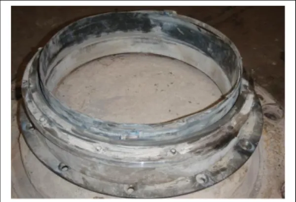
Among other already mentioned factors to seal deterioration in raw mill 7 are grease hardening and raw material invasion. Figure 25 shows the worn lip seal of raw mill 7th grinding roller when disassembled.
18 Furthermore, the mating surfaces play a crucial part in the longevity of the seals. The finish on the shaft is an essential component. Seals are easily damaged by, for example, sharp edges and imbalances in the shaft finish. The finish should, as such, match the material of the seal and seal type. Rough finishes will cause excessive wear on the seals, while a smooth finish will make it challenging to keep the lubricants from spilling out [6].
Any given machine that uses some type of bearing and shaft should take into account the shaft movement. The displacement of the shaft will put the seal under abnormal pressure. In this case and in the case of poor assembly, the seal will be subjected to unbalanced compression. One section of the seal will, by that, be more compressed than the other sections, which causes specific, and excessive wear on the compressed section while the uncompressed ones will experience a lot more lubrication leakage [6].
2.2 Harsh Environment
When active, the conditions within the raw mill are all but mild. Due to the constant upwards flow of hot gas and the amount of ground material being produced, a hurricane-like environment is created within. This is illustrated as an upwards red spiral in figure 26. With a large amount of material bouncing on and off the walls and components, one can, with near certainty, assume that this has a significant effect on the wearing of said walls and components. The seals of the grinding rollers are no exception since the seals are located very close to the gas inlet, as marked with green circles in figure 26. Furthermore, when examining the rollers, it is apparent that the sealing glands are very much exposed to the environment and, as such vulnerable to the hurricane-like material flow. This exposure can make it a lot easier to infiltrate the seals or at least attempt to do so. Figure 18 shows the exposed glands of the grinding roller, and the assumption can be made that it might not be sufficiently protected against incoming material.
A previous engineering thesis studied the different relations within the similarly functioning, but exceptionally larger Polysius raw mill, raw mill 8 in Cementa AB. The study examined
Figure 26. Typical roller mill layout. (illustration of inside hurricane-like environment). From [24].
19 wear due to abrasion and erosion within the mill. When producing the raw flour, materials such as limestone and marlstone, as well as adhesives such as quartz sand and iron ore are mixed together on the milling table inside the raw mill. The roller grinders then grind the material into a fine flour. The quartz sand is considered to be the hardest out of the material with the hardness of 810 Vickers. The quartz sand is often round and without cracks with a crystal-like structure as shown in figure 27, while, for instance, calcite, which is the main element in limestone, is relatively easy to break because of the nature of its structure as shown in figure 28. As such, the sand has a hard time getting ground by the rollers and tends to bounce between the mill walls with relatively high speed due to the constant flow of gas from below. Due to the sand being challenging to destruct and lack of plastic deformation, collisions of sand against the components within the raw mill causes erosion and abrasion in the form of micro-cuts and micro-failures. According to the study, the most prominent wear takes place around the milling table and at the entrance to the classifier, with erosion and abrasion being the primary factors for wear [7].
The study then aims to examine the possibility of maintenance cost reductions by selecting a new, more durable material for the raw mill 8 circuit. The choice of material is built on the wear resistance, life cycle, and price. The study then concludes that the best type of material, in that case, is a hard one with high resistance to erosion and selected material for the task being Triten T266X [7].
2.3 Tribology
Tribology studies can be dated back to 1493. It was then that Leonardo da Vinci created the first two fundamental laws of friction [8]. Methods for estimation of the magnitude of friction have been studied for the past 200 years as well [9].
Tribology is the study and science of the tribological behavior of applications. This includes lubrication, friction, and wear of interacting elements and contact surfaces of a given machine. How the machine system behaves in a dynamic or relative motion largely depends on the design and lubrication method of it. The science is very complex with countless research and researchers around the collaborating to further understand the mysteries of tribology. Figure 29 illustrates the main points of tribological optimization and design.
20 Generally, lubrication acts as a barrier or film between two or more moving surfaces which allows for the reduction of friction, which is the key objective of any given lubrication, and is most commonly in a fluid state but can also, in some cases, be a solid substance. Apart from friction, lubricants help to prevent excessive wear, corrosion and can be used to regulate the temperature within the application by dissipating heat. Also, some lubricants have the ability to regulate contamination by transporting the foreign material to filers as not to wear down the components further. The most common of lubrication substances used in mechanical components are oil and grease. What determines the choice of lubrication is the application they are meant for [10].
A doctoral thesis studied the tribological behavior of elastomers used in different seals. The purpose of a sealing component is mainly to hinder forms of lubricants from accessing a delicate machine process. Leakage of lubricants can cause serious harm to whatever the process may be. When it comes to seals, elastomers have proven to be the most useful and reliable type of material. Since seals often are used in the presence of lubricants, the interaction between the lubricant and the seal elastomer can prove to be of utter importance when researching the tribological effects that can occur. Also, since seals often slide against a surface, they really need to be optimized for friction, which, when excessive, causes leakage and eventually failure. For some seals, such as the so-called reciprocating seals, contamination in the form of leakage can be minimized by increasing the pressure on the sealing surface and decreasing lubrication. However, when reducing the amount of lubrication, some risks can be aggravated due to vibrational factors of the machine. The study also thinks it is worth looking into the tribological performance of operation under dry conditions since the elastomers are affected by frictional wear at times. For instance, during the upstart of the machines.
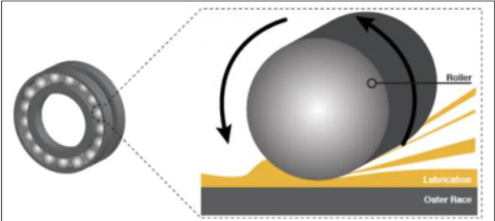
21 Furthermore, the study researches the effects that age has on the elastomeric seals as well as how lubricants influence the wearing on seals due to abrasive wear. The study then concludes that lubricants do, in fact, play a major role in the abrasive wear on the seals due to them constantly being in contact with the lubricant, which in turn weakens the elastomer chosen for the seal. Also, the study showed that the worn particles on the seals where especially aggregated when in a dry state, and the lubrication did somewhat calm down the agitation process [11]. Lubricants are used in a wide variety of applications, but for the sake of this thesis, the focus will be on bearing lubrication. Figure 30 illustrates the lubrication action within a roller bearing.
A crucial factor when researching lubricants is viscosity and it is an important property of any lubricant to have understood when attempting to select one for a specific application. Viscosity is known as the measurement of internal friction within a given lubricant, or fluid in general. Contributing factors to the variation of viscosity in lubricants are pressure and temperature. In some cases, even the shearing rate of the lubricant. Furthermore, research of the tribological nature of any lubricant relies heavily on the viscosity properties of them [12].
Figure 31 shows the state of the grease inside the grinding roller bearings of raw mill 7 when disassembled after failure mode.
Figure 30. As bearing speed increases, lubrication is "pulled into" the contact zone. From [27].
22 Another doctoral thesis from Luleå university of technology studied the influence that grease-based lubrication has on the performance of bearings by examining and evaluating the so-called rheological properties of grease, which include the differences between normal and shear stress with regards to the sealing system in place. By this, the study focuses on the relations between grease-based lubrication, grease-lubricated bearings, and the sealing properties of grease. The aim of the project was to create models to understand better, predict, and analyze grease behavior and function when in operation and to understand better the overall conditions that the grease is operating within. The thesis then implies that it is not entirely clear how seals function in conjunction with grease despite the amount of theoretical as well as experimental research that has been conducted in the field of tribology the past few decades [13].
According to the thesis, about 80-90% of all bearing use some type of grease-based lubricant. This is due to the ease of which it can be applied and the minimal leakage. Also, the friction within the bearings is quite low once the component has been running for a while, and the grease is fully distributed throughout the bearing canals. Also, the oil within the grease is continually lubricating the contact surfaces of, for example, the seals in place. This property is called oil bleeding and is an essential factor for the performance of both the bearings and seals [13]. The thesis presented an extensive amount of literature study of grease lubrication, sealing and lubrication conditions with a lot more tribological research intertwined [13].
Due to the broad scope of the study, the thesis then goes on to present many conclusions related to each research concerning grease lubrication. Among them was a very interesting conclusion regarding the relationship between the grease lubricant and the sealing contact. The high shearing rates of grease near the sealing surface, in conjunction with the normal stresses of grease, may result in a lifting force on the sealing lip. However, the author stresses that the significance of this is inconclusive and that it needs more testing [13].
Applications or machines that operate in high temperature and speed generally benefit a lot more from oil-based lubricants since the oil helps to transfer heat away from the surfaces of the bearings. The oils are usually synthetic oils but often, and most commonly, mineral-based with a set of additives for the prevention of oxidation on the surfaces. Mineral and synthetic oils are quite different in regard to specific properties. One of the crucial characteristics kept in mind when selecting an oil-lubricant for a bearing is the viscosity of it. Specifically, for oil, there exists a correlation between the viscosity and the created film thickness of the oil. The thickness is a significant factor in the separation action of the elements within the bearings. The elements being sliding and rolling. Oil is common in some applications, but for the most part, grease is the preferred option for about 80-90% of all bearings [14].
When it comes to grease, the consistency is made up of about 85% oil, synthetic or mineral, and additives that act as thickeners to sort of round out the volume of the grease, which is what gives the grease its signature texture as opposed to oil that is in a more fluid state. Thickeners are mostly in the form of different kinds of metallic soaps, calcium, or lithium. The immediate benefit with grease is the high viscosity that helps it sit in the application with minimal leakage. Important aspects when selecting a grease for any given application is the viscosity of the base oil, oxidation prevention capabilities, and the range of operating temperature [14].
23
2.4 Vibration
It is usual for a mechanical gadget to vibrate. However, should the device have any sort of imbalance within its components, then seal failure is imminent due to the excessive vibrations that are produced by the imbalance. Almost any dynamic seal needs a lubrication film between itself and the surface of its sealing counterpart. Vibration, especially excessive vibrations, could prevent the lubricating film from settling. This increases the wear factor of the elastomer used and significantly contributes to an early seal failure. One way to detect and eventually limit the conditions that are created from vibration is periodic maintenance. This includes rinsing the gadget from invasive material that could potentially cause these imbalances that also have a significant negative effect on the bearings as well as the shaft when it comes it displacements and misalignments. Bearings can also play a crucial part in the vibrational aspects of a sealing mechanism. Poorly installed bearings that are loose contribute heavily to vibrations that carry over to seal failure. This also includes poorly adjusted or assembled components that have an effect on the dynamic system. Furthermore, it is essential to further touch on the importance of proper alignment of components. If two sealing surfaces aren’t precisely matched, then uneven wear on each of them is the result, as well as the risk of excessive lubricant leakage. Uneven wear is when one part of a seal is being worn more than the other parts. Also, another type of misaligning other than the surrounding components is a misalignment of the sealing mechanism itself due to the excessive vibrations produced by the presented causes. The vibrations force the sealing mechanism out of alignment, which puts unnatural stress on the seal and is a significant factor for seal failure [15].
A study from 2004 researched the behavior of dynamic radial lip seals with the aid of numerical and experimental testing to determine the effects of radial vibrations in a rotary sealing environment. The study defined the parameters in which the behavior of dynamic seals could be characterized to achieve a correlation between the sealing conditions and vibrational effects. The parameters being: Rotating speed, machine operating cycles, temperatures, lubricant viscosity, elastic properties of the seal, static eccentricity, dynamic eccentricity, and assembly interference. The study suggests that the total effect of the parameters determines the stress distribution on the seal when influenced by vibrations in the machine, and that ultimately leads to displacements. The study then concludes with the suggestion that there does in fact exists a relationship between displacement due to, among other factors, vibration and lubricant leakages caused by seal wear and failure [16].
24
3
P
ROCESS FOR REDESIGNING THE SEALING MECHANISM
The process of redesigning a new sealing mechanism will undergo a set of steps. Firstly, data in the form dimensions of the grinding roller and the existing sealing solution will be gathered from internal sources. If needed, manual data gathering will be conducted on one of the rollers currently being maintained in the maintenance workshop. This data will be used to model the current grinding roller and its sealing mechanism first. This is to get a clear idea of the functionalities within the roller in a 3D environment. Furthermore, since raw mill 8 has a functioning sealing mechanism that supports oil-based lubrication, it will be worth comparing the two for inspiration. Of course, in the case that inspiration is found in raw mill 8, the measurements will have to be scaled down and adapted since the grinding roller of raw mill 8 is much larger. Further inspiration will be searched for from existing grinding that other companies manufacture and own. This will be done by researching the web as well as attempting contact with the companies. Furthermore, a short study on standard sealing mechanisms will be conducted to get a better idea of the range of standard selections that could either be implemented or drawn from inspiration-wise. Lastly, an idea-generating phase will ensue where the different inspirations and studies will come in play, and a decision will be made on how to proceed with the actual conceptual designing. The final designs might heavily draw from the presented inspirations and standards, or they might be utterly revolutionary as the freedom of such has been granted by Cementa. For designing the CAD software environment, Autodesk Inventor will be used.
3.1 Data collection
Throughout this project, field studies in the factory were conducted during the annual maintenance shutdown. This is a complete shutdown of all machines in the factory with planned succession. This created a valuable opportunity to observe raw mill 7 in a stationary state as well as the grinding rollers. Since the rollers that had been in operation for a time were extracted and sent for renovation, the chance to observe all the inner components within the roller arose. This includes the sealing mechanism. At first, the plan was to gather data and dimensions of the components with manual measuring as soon as the roller was disassembled in the renovation workshop. However, it was later found out that there exist drawings of the machine that could be apprehended through the internal system. This did not mean that the observations of the actual machine were made redundant since it gave a clearer picture and idea of the relations within that made it easier to visualize the relationships continuing forward.
Apart from the already presented cross-section of the grinding roller in figure 13, appendix 3 shows further internal drawings that were apprehended and worked with.
25
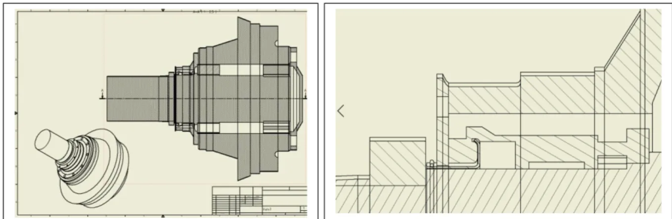
3.2 Modelling raw mill 7th original Grinding roller
To further visualize the current grinding roller and its sealing mechanism as well as visualizing what upgrades can be made later in the project, it was decided to 3D model it using Autodesk Inventor. The drawings in appendix 3 were used to some extent. However, due to some of the components not having a specified dimension within the drawings, it was also decided to create a rough model instead, which means that the model wasn’t made to scale. In fact, many of the component modelling, such as the sealing mechanism, was basically free hand-drawn with the help of figure 13 as a guideline. In the case of this project, it is totally acceptable since it lines up with the scope of the project being the creation of a conceptual design. This will become the case for practically all final conceptual models in the thesis. Below figures 32-36 present the modelled original grinding roller.
Figure 36. Original grinding roller 3D model.
Figure 34. Original grinding roller 3D model.
Figure 32. Original grinding roller Cross section. Figure 33. Original grinding roller cross section of sealing mechanism.
26
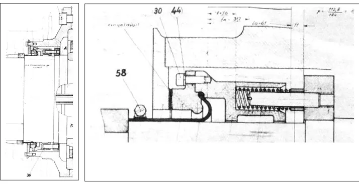
3.3 Inspiration from raw mill 8
Since the grinding roller of raw mill 8 has a functioning sealing mechanism that supports oil-based lubrication, it seemed like a good idea to compare the two in the hopes of at least finding inspiration when generating ideas for a concept regarding raw mill 7. Figure 38 shows a cross-section of raw mill 8th grinding roller. Figure 39 shows a cross-section of the sealing mechanisms in place. Roller 8 is, however, very different from roller 7. It should also be noted the number of O-rings used in different sections of the roller as presented in table 1. This means that the roller most likely has more than one sealing mechanism. The differences are by that too broad and inspiration will have to be found elsewhere.
3.4 Inspiration from other companies
Another alternative for finding inspiration was exploring other companies’ websites that specialize in roller seals or raw mills in general. It stood to reason that many of these companies would have relatively modern grinding rollers implemented in their plants. It was, however, later apparent that they don’t post descriptions of their products, at least not the necessary details for the concept generating phase, online for everyone to see and eventually copy. This made a lot of sense, so contacting them personally seemed fitting. However, this idea was also scrapped since the chances of the companies handing over product specifications to a rival company were slim. In the end, the concept of taking inspiration from other raw mill manufacturers was ultimately scrapped.
Figure 38. Raw mill 8 grinding roller cross section.
Figure 37. Raw mill 8 grinding roller cross section.
27
3.5 Examples of standard seals
The next step was researching established standard sealing mechanisms to get a better understanding of the range of rotary seals that could be applicable in raw mill 7. Below are three types of rotary seals that inspiration could be drawn from. The choice of the three specific types of seals was made through research on what would be considered the best alternatives on the market for rotary type equipment in need of sealing and as such would fit the needs of raw mill 7.
3.5.1 Rotary shaft seals
The lower edge of the seal, or sealing edge, is considered to be the most important since it is also the contact point between the seal and the shaft. The rotary shaft seal is also known as one of the many versions of lip seals that exist. The internal diameter of the rotary seal is a bit smaller than the diameter of the shaft, which creates a natural pressure from the seal on the shaft. Furthermore, a garter spring mounted on the seal makes it so that constant pressure is generated onto the shaft. This action also somewhat flattens the sealing edge. As with almost all lip seals, a lubrication film, preferably oil, is created between the flattened sealing edge and the shaft. This creates a sort of surface tension. To avoid leakage of oil, the choice of viscosity has to be carefully made with regards to the sealing environment [17].
3.5.2 Dynamic rotary gland seals with O-rings
A dynamic rotary gland seal utilizes the O-ring as a sealing entity. However, because of the many interacting forces that, due to the bigger surface tensions that are generated, it is
Figure 39. Rotary shaft seal. From [17]. Figure 40. Rotary shaft seal. From [17].
28 recommended that the choice of elastomers for the O-ring be carefully investigated with regards to the sealing environment [18].
It is, therefore, essential to conduct a short study about the O-ring and its functionality.
The most common of sealing components is the O-ring and is the most basic type of seal that is widely used in the industry. The O-ring is like a doughnut-shaped ring and comes in many sizes. Some O-rings are made of thermal plastic, but for the most part, most O-rings are made of elastomers, which are basically rubber. A rubber seal can be seen as an incompressible, extremely viscous fluid that is put under constant high pressure. Figure 44 illustrates the seal when newly installed. Figure 45 shows the seal having to start flowing towards the grooves due to added pressure from fluids. Figure 46 illustrates the seal at a pressure limit. Figure 47 illustrates the failed seal [19].
The primary usage of an O-ring is to conveniently seal off and prevent leakage of lubricants as well as keep foreign material from entering. Substantial research funds have been dedicated to studies on the sealing capability of O-rings. Institutions like NASA are among the many organizations that have realized the importance of performance studies on the sealing technology. The seal is used in a wide variety of mechanical structures in the conditions of both dynamic and static contact [20].
The design of a dynamic and a static O-ring is different in some ways. A dynamic O-ring seals between two or more moving parts, often in a rational motion. It is then especially important to choose a material that is relatively hard-wearing. Also, a crucial aspect when selecting a dynamic ring is the design of the environment that it is placed in. The situation that the O-ring is positioned within should take into consideration the weaO-ring inducing factors of sheaO-ring and abrasion that most likely will deteriorate and destroy the O-ring prematurely because of the near-constant movement of the surfaces. This is certainly less of a hindrance for static seals since basically the only force they will have to endure is that of static compression, which they have been proven to be quite resilient towards. Proper maintenance is still required, though. Furthermore, a dynamic O-ring requires more lubrication with more frequent application than its counterpart, and for optimal sealing performance, the quality and type of material need to be
Figure 44. From O-ring installed. From [19].
Figure 46. O-ring failure. From [19]. Figure 45. O-ring extruding. From [19].
29 determined when manufacturing them based on the dynamic movement they are meant to perform within [21].
Below table 2shows some examples of material-performance for O-rings.
Table 2. Material for O-ring and advantages/disadvantages. From [20]
The structure design of the environment around the O-ring in which it is situated enables compressive sealing. Within the seal, the housing mechanism is a groove that the O-ring completely and entirely covers. The groove allows for the insertion of the O-ring in a circumferential direction in either an inner or outer diameter side of a given shaft, provided that the sealing is of rotational nature. The sealing design then performs with the help of repulsive elasticity due to the deformation that is generated because of the compression. The rubber materials restoration force is then taken advantage of during the sealing action [20].
Below figure 47 illustrates the compressive force.
![Figure 11. Typical roller mill layout. From [24]. Figure 12. Structure of raw mill 7 from the outside](https://thumb-eu.123doks.com/thumbv2/5dokorg/4278881.95162/14.892.488.733.830.1149/figure-typical-roller-layout-figure-structure-raw-outside.webp)
![Figure 29. Schematic representation of tribological optimization. From [26].](https://thumb-eu.123doks.com/thumbv2/5dokorg/4278881.95162/28.892.184.686.106.550/figure-schematic-representation-tribological-optimization.webp)