http://www.diva-portal.org
Postprint
This is the accepted version of a paper published in International Journal on Software Tools
for Technology Transfer (STTT). This paper has been peer-reviewed but does not include the
final publisher proof-corrections or journal pagination.
Citation for the original published paper (version of record):
Enoiu, E P., Causevic, A., Ostrand, T., Weyuker, E., Sundmark, D. et al. (2016)
Automated Test Generation using Model-Checking: An Industrial Evaluation
International Journal on Software Tools for Technology Transfer (STTT), 18(3):
335-353
https://doi.org/10.1007/s10009-014-0355-9
Access to the published version may require subscription.
N.B. When citing this work, cite the original published paper.
Permanent link to this version:
Automated Test Generation using Model-Checking: An
Industrial Evaluation
Eduard P. Enoiu1, Adnan ˇCauˇsevi´c1, Thomas J. Ostrand3, Elaine J. Weyuker1, Daniel
Sundmark12, and Paul Pettersson1
1 M¨alardalen University, V¨aster˚as, Sweden.
2 Swedish Institute of Computer Science
3 Software Engineering Research Consultant
Abstract. In software development, testers often focus on functional testing to validate implemented programs against their specifications. In safety critical soft-ware development, testers are also required to show that tests exercise, or cover, the structure and logic of the implementation. To achieve different types of logic coverage, various program artifacts such as decisions and conditions are required to be exercised during testing. Use of model-checking for structural test genera-tion has been proposed by several researchers. The limited applicagenera-tion to mod-els used in practice and the state-space explosion can, however, impact model-checking and hence the process of deriving tests for logic coverage. Thus, there is a need to validate these approaches against relevant industrial systems such that more knowledge is built on how to efficiently use them in practice. In this paper, we present a tool-supported approach to handle software written in the Function Block Diagram language such that logic coverage criteria can be for-malized and used by a model-checker to automatically generate tests. To this end, we conducted a study based on industrial use-case scenarios from
Bom-bardier Transportation AB, showing how our toolbox COMPLETETESTcan be
applied to generate tests in software systems used in the safety-critical domain. To evaluate the approach, we applied the toolbox to 157 programs and found that it is efficient in terms of time required to generate tests that satisfy logic coverage and scales well for most of the programs.
1
Introduction
Advances in model-checking tools and technology in the last decade have made it a pragmatically usable technique for test case generation from finite-state models [13]. There have been a number of approaches used for defining logic coverage using model checkers, e.g., [7, 24, 25], however, these techniques are not directly applicable to real-world programs of critical systems. When industrial software systems are being tested, there is still the issue of potential combinatorial explosion of the state space which thereby limits the application to models used in practice.
Many industrial application domains use safety-critical software to implement the behavior of programmable logic controllers (PLCs). One of the programming languages defined by the International Electrotechnical Commission (IEC) for PLCs is the
into program code, which is compiled into machine code by using specific engineering tools provided by PLC vendors. The motivation for using FBDs as a preferred language arises because it is the standard in many industrial software systems, such as in the rail-way domain. Such systems typically require a certain degree of certification [8], such as some level of logic coverage which must be demonstrated on the developed software. Although all software should aspire to correctness, safety critical software is gener-ally held to a higher standard than other types of systems, which should be reflected in their testing. However, there is no commonly accepted level of test thoroughness for safety-critical software. In this paper, we show how to efficiently generate test cases that achieve several levels of coverage, including MC/DC and decision coverage. It should be noted that the generated tests are not intended to replace requirement-based test design at the FBD program level, but to complement it with a structural perspective. In our previous work we proposed the use of logical coverage for FBD programs
[12] and defined a model-based test generation method based on the UPPAAL tool.
While this approach is promising, there is a need to validate it using realistic pro-grams of critical systems. To this end, we conduct an experimental evaluation using 157 programs of a train control system, written in the FBD language. We develop a
toolbox, named COMPLETETEST4, suitable for transforming an FBD program to a
for-mal representation of both its functional and timing behavior. This is done by imple-menting an automatic model–to–model transformation from FBDs to timed automata. Timed automata, introduced by Alur and Dill [3], were chosen because there is an al-ready existing formal semantics and tool support for simulation and model-checking
using UPPAAL[22]. The transformation accurately reflects the data-flow characteristics
of the FBD language by constructing a complete behavioral model which assumes a
read-execute-writeprogram semantics. The translation method consists of four
sepa-rate steps. The first three steps involve mapping all the interface elements and the ex-isting timing annotations. The final step produces a formal behavior for every standard component in the FBD program. These steps are independent of timed automata and therefore are generic in the sense that they could also be used when translating an FBD program to a different target language. The toolbox uses a test generation technique based on model-checking, tailored for logic coverage of FBD programs. A generated test consists of a sequence of input vectors. As the main purpose of the tool at present is to generate test cases that satisfy coverage criteria, the tool does not generate expected outputs. Expected outputs can be provided manually to the toolbox by a human tester.
The paper is organized as follows. Section 2 provides an overview of PLC software, the IEC 61131-3 standard, timed automata and logic coverage. Section 3 describes the transformation scheme into timed automata. Section 4 and Section 5 present the test case generation method required for logic coverage criteria. In Section 6, we describe the tool box used for testing FBD software and demonstrate its application by showing relevant user scenarios. In Section 7, we evaluate the toolbox on industrial programs in terms of its efficiency and usability. Section 8 describes related work. Section 9 presents our conclusions.
4C
2
Preliminaries
This paper describes a toolbox for generating tests that cover the logical structure of FBD programs, by transforming them first to networks of timed automata. Our tech-nique will be illustrated throughout this paper using a complete, small, but non-trivial FBD program that exhibits many of the features of FBDs. We show how this program can be translated into a timed automaton and used to illustrate the approach, the toolbox evaluation and its practical implications. In this section, we provide some background details on FBD programs, timed automata and logical coverage.
2.1 Programmable Logic Controllers
PLCs are widely used in real-time software for many types of software systems in-cluding nuclear plants and train systems. A PLC is an integrated embedded system that contains a processor, a memory, and a communication bus. The semantics of a program running on a PLC has the following representative characteristics:
– programs execute in a cyclic loop where every cycle contains three phases: read (reading all inputs and storing the input values), execute (computation without in-terruption), and write (update the outputs).
– Input and output channels correspond to sensors and actuators respectively. The language can be specified on an implementable subset of timed automata [3]. Dierks [10] proposed a new class of automata suitable for PLCs and this definition is the basis for implementing a model-to-model transformation for PLC software.
FBD, a PLC programming language standardized by IEC 61131-3, is very popular in industry because of its graphical notations and its data flow nature [23]. Blocks in an FBD program form the basis for a structured and hierarchical application. They may be supplied by the manufacturer, defined by the user, or predefined in a library. An application generator is utilized to automatically transform each block to a C compliant program with its own thread of execution. A block cannot be recursive as it cannot call itself [27]. However, blocks may have multiple instances within a program.
Although our description is not limited to a particular PLC software development style for FBD programs, it is exemplified by a generic PLC control application com-pliant with the IEC 61131-3 standard. A PLC periodically scans an FBD application program, which is loaded into the application memory. As an example of the FBD generic model, we consider first the hierarchical structure of a PLC and the functional integration. An FBD control program is considered as a hierarchical application. The FBD program is created as a composition of interconnected blocks, which may have intra-program data flow communication. When activated, a program consumes one set of input data and then executes to completion. The code is used on the specific PLC and is the actual application code from the IEC 61131-3 compliant FBD program.
The IEC 61131-3 standard proposes a hierarchical software architecture for structur-ing and runnstructur-ing any FBD program. This architecture specifies the syntax and semantics of a unified control software based on a PLC configuration, resource allocation, task control, program definition, function and function block repository, and program code [23, 27].
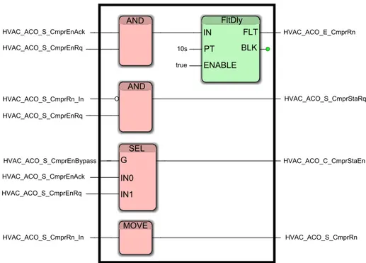
AND FltDly AND SEL MOVE IN FLT BLK PT ENABLE G IN0 IN1 HVAC_ACO_S_CmprEnAck HVAC_ACO_S_CmprEnRq HVAC_ACO_S_CmprRn_In HVAC_ACO_S_CmprEnRq HVAC_ACO_S_CmprEnBypass HVAC_ACO_S_CmprEnAck HVAC_ACO_S_CmprEnRq HVAC_ACO_S_CmprRn_In HVAC_ACO_S_CmprRn HVAC_ACO_C_CmprStaEn HVAC_ACO_S_CmprStaRq HVAC_ACO_E_CmprRn 10s true
Fig. 1. Running Example: Compressor Start Enable program showing the graphical nature of the language.
The systems we are studying contain a particular type of blocks called PLC timers. These timers are output instructions that provide the same functions as timing relays and are used to activate or deactivate a device after a preset interval of time. There are two different timer blocks (i) On-delay Timer (TON) and (ii) Off-delay Timer (TOF). A timer block keeps track of the number of times its input is either true and false and outputs different signals based on these counters. In practice many other time configura-tions can be derived from these basic timers. In order to study how to generate test cases using a model checker for these types of FBD programs, we use a formal representation that can cope with timers and timing information.
2.2 The Compressor Start Enable Program
The translation scheme, test generation, and logic coverage will be illustrated by trans-lation of a complete, small, but typical FBD program that includes many of the FBD features. Figure 1 contains this FBD program for which we will ultimately generate test cases. It was developed by an engineer from Bombardier Transportation responsible for developing train control software in V¨aster˚as, Sweden.
The train is made up of motorized cars and intermediate trailer cars with pan-tographs. These cars are combined to create a fixed eight car train, each with its own complete software control system that applies regulation to a heating and/or air con-ditioning system. The task of the train operating the ventilation compressor mode is
imposed by the controller FBD program depicted in Figure 1. The program requests permission to start the ventilation compressor from the auxiliary load control. When granted, it will forward the command to the ventilation controller. The Compressor Start Enable will request permission to start the ventilation compressor. When granted, the signals are forwarded to the ventilation controller.
The request will time out (HVAC ACO E CmprRn) when the compressor start signal is acknowledged (CmprEnAck) and required (HVAC ACO S CmprEnRq) provided the clock is greater than or equal to ten seconds. Additionally, the ventilation should be ac-tive (HVAC ACO S CmprRn) when the compressor is running (HVAC ACO S CmprRn In). The ventilation request is started (HVAC ACO S CmprStaRq) when the compressor is en-abled (HVAC ACO S CmprEnRq) and the compressor is not running (CmprRn In). When the external supply (CmprEnBypass) is not available, the compressor should be enabled (CmprStaEn) only when the compressor is allowed to start from auxiliary load control (HVAC ACO S CmprEnAck). If the external supply is available, then the compressor is enabled.
The program consists of basic functions (e.g., AND, SEL, MOVE) and function
blocks (e.g.,FltDly). In Figure 1,AND is a function. In contrast,FltDlyis a function
block because it maintains an internal state and produces outputs based on this state and inputs. Recall that in order to express timing constraints within one component, standard PLC timers are used. The timers in a PLC are operated by an internally gen-erated clock that originates in the processor module. Consider the following PLC timer FltDly defined as a tuple:
FltDly= hFltDly1, (IN, PT, ENABLE, FLT, BLK), Bti,
where FltDly1 is the name identifier, IN, PT , ENABLE, BLK, and FLT are the
set of ports and parameters in Port, and Bt is the behavior description. This timer
component is an attempt to specify its interface and behavior. From a semantic point of view, FBD programs are a special case of deterministic reactive systems. We use more informative notations to denote the actual behavior. In the following section we present
several such notations to describe how FBD programs can be handled by the UPPAAL
model checker.
2.3 Networks of Timed Automata
A timed automaton is a standard finite-state automaton extended with a collection of real-valued clocks. The model was introduced by Alur and Dill [3] and has gained in popularity as a suitable model for real-time systems. We consider model checking
algorithms that perform analysis to check for a reachability property of the form ∃♦ β .
∃ is the existential quantifier, ♦ is the temporal operator meaning eventually, and β is a formula designed to capture the requirements of a particular type of logic coverage. The reachability property states that there exists a path σ through the states of the timed automaton such that β eventually holds. The property is presented to the model checker, which then attempts to find an actual path that satisfies the property. A path σ that satisfies the reachability property can be converted into a test case that satisfies the desired coverage. We use a timed modal logic to specify properties. The logic may be
seen as properties that can be expressed as logical formulae in the Timed Computational Tree Logic (TCTL) [2].
An example of a network of timed automata modeled in UPPAALis shown in Figure
2. The network consists of an automaton of a lamp and an automaton of a user. A network of timed automata in this case can be written as Lamp k U ser. The user operates the lamp by pressing the on/off switch. By pressing the switch, the lamp can be in three possible locations: Off, Dim and Bright. The automaton of the lamp starts at the Switched Off location and contains one clock x. If the user presses the light switch, the lamp switches to Dim and the clock is reset, by the update assignment x := 0. When Dim, the lamp remains on as long as the clock is less than or equal to five time units (i.e., invariant x <= 5). A state of the automaton Lamp depends on its current location and on the current values of its clocks. If the user presses the light switch before three time units, then the lamp switches to location Bright. In this location, the lamp automaton stays ON until the user presses the light switch again. Both automata synchronize via the actions press! and press? i.e., by sending via channel press! and receiving using press?. Based on the states of the Lamp automaton, one can denote traces starting from
the initial state as a sequence of alternating transitions σ = (Off , 0)−−−→ (Dim, 0)press −−−→delay
(Dim, 2)−−−→ (Bright, 2).press
Fig. 2. Example of a network of timed automata.
We provide a brief summary of the notation and concepts in Appendix A, for readers unfamiliar with timed automata theory. Further information can be found in [1].
2.4 Logic-based Coverage Criteria
Coverage criteria are a code-based means of assessing the thoroughness of test cases. They are normally used at the unit test level to check that various aspects of the code structure have been exercised by the test cases. Out of the many criteria that have been defined and studied, we have implemented three logic-based criteria that measure the thoroughness of test coverage of the control flow structure of FBD programs.
FBD program flow is controlled by atomic Boolean expressions called conditions, and by decisions made up of conditions combined with Boolean operators (NOT, AND, OR, XOR, IMPLIES, EQUIV). A condition can be a single boolean variable, an arith-metic or character comparison with a Boolean value (e.g., A > B or str1 == str2), or a call to a function with a Boolean value, but does not contain any Boolean operators. The test generation tool uses the UPPAAL model checker to generate test cases that satisfy three types of logic coverage: decision coverage DC (also known as predicate cover-age), condition coverage CC (also known as clause coverage) and Modified condition decision coverage (MC/DC).
A set of tests satisfies decision coverage if running the test cases causes each de-cision in the FBD program to have the value true at least once and the value false at least once. Note that for any individual predicate, the true and false values might occur under a single test case or under two different test cases. In general a single test case will exercise more than one decision, and it is possible, but certainly not required, that all decisions in a program might have both values exercised by a single test case. In the context of traditional sequential programming languages, decision coverage is usually referred to as branch coverage.
Condition coverage requires test cases that cause each individual condition to be ex-ercised at least once with value true and once with value false. A set of test cases might satisfy either condition coverage or decision coverage, or both of them. Modified con-dition decision coverage captures the idea that the value of a decision can be controlled by the value of each of its conditions independently of the values of all other conditions. This means that for each individual condition c in a decision, there are sets of values of all the other conditions so that the decision’s value differs for the two possible values of the condition c.
For MC/DC each individual condition in each decision should be shown to be able to determine the outcome of the decision during testing. MC/DC is a stronger requirement than CC; any test set that satisfies MC/DC must also satisfy CC. For most non-trivial decisions, MC/DC is also more strict than DC, even though there are decisions for which a MC/DC-satisfactory test set does not satisfy DC. CC, DC and MC/DC, as well as other logic criteria, are defined and exemplified in [9, 5].
3
Translation
The translation scheme will be illustrated on the running example. After translation, the UPPAALmodel checker can be applied to test that the program satisfies the required logic coverage on the FBD program. The translation is performed starting from signals which are translated into global variables shared by the corresponding blocks. Addi-tionally, FBD blocks are mapped to input/output behavior (e.g., functional and timing)
between signals. This may be done by using predefined UPPAALoperators, as in the case of basic blocks (e.g., AND, SEL, MOVE), or by capturing the functionality of more
complex blocks(e.g., FltDly) from their description.
In practice the timed behavior of an FBD program is defined as a network of timed automata, extended with data input and output variables. We first perform an automatic transformation of the FBD program to timed automata that obeys the
read-execute-writesemantics of the FBD program, hence preserving the semantics of FBDs without
altering its structure. Next, we specify the execution of each block, and construct a complete timed automata model by the parallel composition of local behaviors.
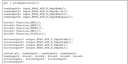
1 plc = p l c S u p e r v i s i o n (); 2 3 r e a d i n p u t 1 = i n p u t _ H V A C _ A C O _ S _ C m p r E n R q (); 4 r e a d i n p u t 2 = i n p u t _ H V A C _ A C O _ S _ C m p r R n _ I n (); 5 r e a d i n p u t 3 = i n p u t _ H V A C _ A C O _ S _ C m p r E n A c k (); 6 r e a d i n p u t 4 = i n p u t _ H V A C _ A C O _ S _ C m p r E n B y p a s s (); 7 8 b l o c k 1 = F u n c t i o n _ A N D 1 (); 9 b l o c k 2 = F u n c t i o n _ A N D 2 (); 10 b l o c k 3 = F u n c t i o n _ M O V E 1 (); 11 b l o c k 4 = F u n c t i o n _ S E L 1 (); 12 b l o c k 5 = F u n c t i o n _ F l t D l y 1 (); 13 14 w r i t e o u t p u t 1 = o u t p u t _ H V A C _ A C O _ C _ C m p r S t a E n (); 15 w r i t e o u t p u t 2 = o u t p u t _ H V A C _ A C O _ S _ C m p r S t a R q (); 16 w r i t e o u t p u t 3 = o u t p u t _ H V A C _ A C O _ S _ C m p r R n (); 17 w r i t e o u t p u t 4 = o u t p u t _ H V A C _ A C O _ E _ C m p r R n (); 18 19 s y s t e m plc , r e a d i n p u t 1 , r e a d i n p u t 2 , r e a d i n p u t 3 , 20 r e a d i n p u t 4 , block1 , block2 , block3 , block4 , block5 , 21 w r i t e o u t p u t 1 , w r i t e o u t p u t 2 , w r i t e o u t p u t 3 ,
22 w r i t e o u t p u t 4 ;
Fig. 3. Interface elements created from structure and behavioral elements from the Compressor Start Enable.
3.1 FBD Structure
For illustration, we start with the translation of the Compressor Start Enable Program. For each block, a timed automaton is defined for the program description. Templates of components are included and we list the composed timed automata network represent-ing the FBD program as
AND1k AND2k SEL1k MOV E1k FltDly1
The top-level structure of the UPPAALmodel is shown in Figure 3 and represents
a parallel composition of several processes corresponding to inputs (lines 3-6), outputs (lines 14-17), and blocks (lines 8-12).
An input named in the program HVAC ACO S CmprEnAck will be automatically translated into a timed automata template named input HVAC ACO S CmprEnAck().
When an input signal in FBD has a name, the name is preserved during translation. However, it is often the case that signals in FBDs are not named (e.g., in the Compres-sor Start Enable program there are simply ”wires“ connecting two blocks). In such a case, the name given to the signal corresponds to the name of the block which pro-duces the signal. For example, the output signal produced by Function AND2() will
correspond to an UPPAALvariable named bool AND2 as shown in Figure 4.
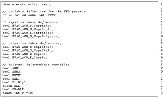
1 c h a n execute , write , r e a d ; 2 3 // v a r i a b l e d e f i n i t i o n f o r t h e F B D p r o g r a m 4 // U S _ I N T OR B O O L V A R _ I N P U T 5 6 // i n p u t v a r i a b l e d e f i n i t i o n 7 b o o l H V A C _ A C O _ S _ C m p r E n R q ; 8 b o o l H V A C _ A C O _ S _ C m p r R n _ I n ; 9 b o o l H V A C _ A C O _ S _ C m p r E n A c k ; 10 b o o l H V A C _ A C O _ S _ C m p r E n B y p a s s ; 11 12 // o u t p u t v a r i a b l e d e f i n i t i o n ; 13 b o o l H V A C _ A C O _ C _ C m p r S t a E n ; 14 b o o l H V A C _ A C O _ S _ C m p r S t a R q ; 15 b o o l H V A C _ A C O _ S _ C m p r R n ; 16 b o o l H V A C _ A C O _ E _ C m p r R n ; 17 18 // i n t e r n a l i n t e r m e d i a t e v a r i a b l e s 19 b o o l A N D 1 ; 20 b o o l A N D 2 ; 21 b o o l M O V E 1 ; 22 b o o l S E L 1 ; 23 b o o l F l t D l y 1 ; 24 c l o c k BLK ; 25 b o o l E N A B L E ; 26 c o n s t int PT = 1 0 ;
Fig. 4. Input, Output, and Internal Signals translated for the Compressor Start Enable Program.
Several Boolean and integer variables are used for recording information in the UPPAALmodel and are shown in Figure 4: read, execute and write synchroniza-tion channels are used to hard code the execusynchroniza-tion of the program, the BLK clock vari-able is used to keep track of the elapsed time in FltDly, other varivari-ables (e.g., bool HVAC ACO S CmprEnRq) are used for recording the inputs generated by the input au-tomaton, PT represents the fault delay, while ENABLE records the compressor enable.
3.2 Cycle Scan and Triggering
A block in an FBD has an interface, consisting of a name identifier, input and out-put ports, and a list of parameters. The interface is used to access the block behavior. When the block is activated the behavior is started using the values read on the input ports. When the behavior ends, i.e., when the block implementation terminates its exe-cution, the output ports are updated. The behavior of a block is typically implemented by a code fragment that updates local variables. In addition, the program contains a clock variable for modeling a delay between the cycles. We show in Figure 5 how a
Fig. 5. Timed Automaton of a Program Cycle Scan and Execution Order.
cycle starts when the automaton enters the ReadInputs node and ends its computation in UpdateScanTime node. For an FBD program, the execute operation of each block is extended according to connections and IN and OUT variables corresponding to the program inputs and outputs. A program composition is a set of interconnected blocks closed under a specific execution order. The execution order N is automatically defined according to the general rules included in the IEC 61131-3 standard. This predeter-mined order directly dictates the data dependency. Using the program cycle requires deterministic program execution, by restricting the underlying timed transition system. The program is executed in a loop and the computation follows the run-to
comple-tionsemantics. We use the notion of precedence to describe such dependencies on the
convention of reading such FBD programs in a top-to-bottom, left-to-right fashion. To show an example of a program cycle scan as shown in Figure 5 different actions are executed:
– read(IN) for reading variables from IN.
– write(OUT) for writing variables onto output ports.
– When the execution order holds, the ports are updated by read(IN), and write(OUT). For the Compressor Start Enable program, the execution order is AND1, FltDly1, AND2, SEL1, and MOVE1. For each block we assign a precedence priority to the corre-sponding timed automaton. A counter is created in this step to represent the execution priority of a block. In this way we ensure that block are executed one by one. After the last block is evaluated, the counter is reset to repeat the scan cycle.
3.3 Translation of basic blocks
– The Logical Operator blocks are translated using the logical UPPAALoperators and, not, or.
– The Arithmetic Operator blocks are translated using the arithmetic UPPAAL
operators +, =, - , /, *.
– The Comparison blocks are translated using the relational operators UPPAAL<,
>, <=, >=, =.
– The Selection blocks are translated using if-then-else statements.
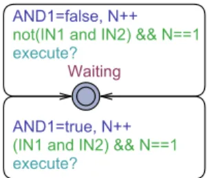
Fig. 6. An automaton showing the AND logical block.
Fig. 7. A Timed Automaton showing a FltDly timer block.
The behavior mapped onto a basic block is modeled as an UPPAALautomaton as
shown in Figure 6 for an AND logical block. The execution of the translated FBD pro-gram is determined in terms of the execution order N. A block is therefore initially in location Waiting, and after performing the read action it starts executing until its
inter-nal computation is done. After completing the write action, which forwards data from the output ports via connections, the block becomes Waiting again.
The parallel processes translated for the basic blocks for the Compressor Start En-able program are the following:
– plcSupervision The automaton in Figure 5 controls the valid structural infor-mation for the other automata. The structure of the FBD program is restricted to reading inputs, execution of the components, and the writing of the outputs. – input name This automaton non-deterministically generates valid input sequences
for the translated blocks. Valid sequences are restricted to Boolean and Integer values.
– block AND1 and block AND2 The automaton in Figure 6 encodes a Boolean AND function by reading the input values and returning a true or false value for the next automaton.
– block SEL1 Selects one of two inputs depending on the value of a Boolean input. Then the translation would be:
SEL1= if(G=true) then SEL1=IN1 else SEL1=IN0.
– block MOVE1 This automaton is a memory function when we turn on the input port.
– output name The output startup-mode automaton checks the current value re-ceived from the function automaton. It also updates the values of the variables OUT and IN.
More stateful blocks are translated into UPPAALautomata. In particular:
– The Bistable blocks (e.g., SR and RS latches) are elements whose output de-pends not only on the current inputs, but also on previous inputs and outputs.
These blocks can be implemented using logical, relational UPPAALoperators and
if-then-else statements.
– The Edge Detection blocks are translated using UPPAALexpressions involving
Boolean operators.
– The Counters blocks are translated by the use of UPPAAL++ increment and
--decrement operators.
– The Timer blocks are translated as a special automaton that is initially in location Waiting. After reading its inputs, it starts executing in location Running until its internal computation is done. After computing the on-delay timer, it forwards data to output ports and the block becomes Waiting again. One example of a Timer block from the Compressor Start Enable program is shown in Figure 7. The FltDly automaton counts time-based intervals when the input is true and activates its output after a preset interval of ten seconds. The cycle scan interacts with the timer block via the execute? action. The timer sets the output FltDly1 to true if IN variable is true at least as long as the time PT and ENABLE are set to true.
4
Testing Function Block Diagram Software using the UPPAAL
Model-Checker
In this section, we describe an approach to automatically generating tests for FBD pro-grams. Logic coverage criteria are used to define what test cases are needed and we use
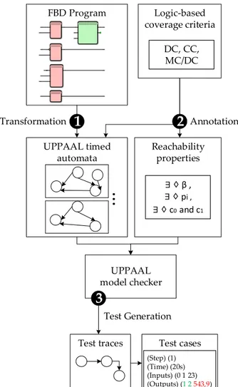
a model-checker to generate test traces. In addition, the methodology presented in this paper is tailored for FBD programs, and is composed of the following steps, mirrored in Figure 8:
1. Model Transformation To test an FBD program we map it to a finite state system suitable for model checking. In order to cope with timing constraints we have cho-sen to map FBD programs to timed automata.
2. Logic Coverage Annotation We annotate the transformed model such that a condi-tion describing a single test case can be formulated. This is a property expressible as a reachability property used in most model checkers.
3. Test Case Generation We now use the model-checker to generate test traces. To pro-vide a good level of practicality to our work, we use a specific model-checker called UPPAALwhich uses timed automata as the input modeling language5. The verifi-cation language supports reachability properties. In order to generate test cases for
logic coverage of FBD programs using UPPAAL, we make use of UPPAAL’s ability
to generate test traces witnessing a submitted reachability property [15]. Currently UPPAALsupports three options for diagnostic trace generation: some trace lead-ing to a goal state, the shortest trace with the minimum number of transitions, and fastest trace with the shortest time delay.
While UPPAALis a viable tool for model checking, it is not directly tailored to test
case generation in practice. We demonstrate how to work around this by automatically generating traces for logic coverage of the control flow of FBD programs described in timed automata and how we transform these traces to actual test cases. We discuss these steps in further detail in the following sections.
As a result of the translation described in Section 3.3, we consider that the FBD program is given as a closed network of timed automata as shown in Figure 9. This model contains two sub-networks, one modeling the FBD Program and the other one modeling its Input and Output Model. In addition, we consider a completely un-constrained input environment that allows all possible interactions between the timed automata network elements. In this way the cycle scan is used to control the FBD pro-gram via read!, execute!, and write! actions. This corresponds to synchronization
actions implemented in UPPAALas a hand-shaking synchronization: two automata take
a transition at the same time, one will have an a! and the other an a?, a being the syn-chronization channel.
Let us assume the generic timed automata network of the Compressor Start Enable program together with its cycle scan (plcSupervision()) and Input/Output models shown in Figure 9. A trace produced by the model checker for a given reachability property defines the set of actions executed on the Compressor Start Enable program which in our case is considered the system model sys. An example of a diagnostic trace has the following form:
(sys0) a1
−→ (sys1)
a2
−→ ... an
−→ (sysn),
where (sysk) are states of the FBD program and PLC supervision with input
environ-ment constraints, respectively, and akare either internal synchronization actions,
time-delays or read!, execute!, and write! global synchronizations. For FBD programs,
5The U
FBD Program UPPAAL timed automata Logic-based coverage criteria Reachability properties UPPAAL model checker
Test traces Test cases
Transformation
2
Annotation Test Generation DC, CC, MC/DC1
∃ ♢ β , ∃ ♢ pi , ∃ ♢ c0and c1...
(Step) (1) (Time) (20s) (Inputs) (0 1 23) (Outputs) (1 2 543,9)3
Fig. 8. Testing Methodology Roadmap
the sequence represents only the global synchronizations shown in Figure 9. Test cases are obtained by extracting from the test path the observable actions read!, execute!, and write!. Obviously all the test obligations cannot be satisfied by a single test case. By using a scan cycle we allow the test to be implemented as one or more paths separated by resets. To introduce resets in the model, we annotate the cycle scan with a reset tran-sition leading to the initial ReadInputs location. On this trantran-sition all variables and parameters (excluding encoded internal variables) are reset to their default value. This
reset is hardcoded into the PLC supervision for any modeled FBD program in UPPAAL,
Input Model
readinput1 readinput2
readinput3 readinput4
Compressor Start Enable
AND1 () AND2 () MOVE1() SEL1 () FltDly1 () plcSupervision () Output Model writeoutput1 writeoutput2 writeoutput3 writeoutput4 read! write! execute! read? read? read? read? IN=1 IN=2 IN=3 IN=4 N=1 N=3 N=2 N=4 N=5 execute? execute? execute? execute? execute? write? write? write? write? OUT=1 OUT=2 OUT=3 OUT=4
Fig. 9. Timed Automata Network of the Compressor Start Enable Program.
5
Analyzing Logic Coverage
The basic approach to generating test cases for logic coverage using model-checking is to define a test as a finite execution path. By characterizing a logic coverage criterion as a temporal logic property, model-checking can be used to produce a path for the test obligation.
Ammann et al. [4] argued that criteria such as logic coverage that have constraints involving more than one test trace cannot be handled in this way. The core problem is that each execution is characterized by a temporal formula, and test obligations span multiple runs of the model checker. This means that to ensure model-checking of MC/DC test obligations one should satisfy constraints on multiple runs of the model-checker. However, an FBD program has an implicit control loop, so a reset transition can occur in the program without modifying the transformed timed automata in any way. This reset transition restores the program to its initial state, making it possible to handle test obligations over multiple program executions as a single execution path containing subpaths separated by resets.
By using a translated FBD program, we use logic coverage to directly annotate both the model and the temporal logic property to be checked. We propose the annotation with auxiliary data variables and transitions in such a way that a set of paths can be used as a finite test sequence. In addition, we propose to describe the temporal logic properties as logic expressions satisfying certain logic coverage criteria. Informally, our approach is based on the idea that to get logic coverage of a specific program, it would be sufficient to (i) annotate the conditions and decisions in the FBD program, (ii) formulate a reachability property for logic coverage, and (iii) find a path from the initial state to the end of the FBD program. To apply the criteria, necessary properties for the integration of logic coverage need to be fulfilled.
For each criterion, model checking allows the generation of paths for logical pred-icates showing test obligations satisfaction. To do so, conditions and decisions have to be formulated as temporal logic formulae. Hessel et al. [16] proposed one way to apply coverage criteria to specifications described in timed automata. We extend this approach to apply it to the conditions and decisions in an FBD program.
Decisions in an FBD program are blocks that can be evaluated to a Boolean value, i.e., true or false. Decisions can be identified from the instrumentation points in the
FBD program (e.g., AND block). Let {di} be the set of decisions in an FBD program
and {ci j} be the set of conditions in di.
DC requires every dito evaluate to true and false, and is described by the following
two test obligations:
o1= di
o2= ¬di
These obligations guarantee that each decision dievaluates to both true and false, not
necessarily along the same execution path.
CC requires two test obligations for each clause ci jin a decision di, such that ci j
evaluates to both true and false:
o1= ci j
o2= ¬ci j
MC/DC imposes two requirements for test cases. First, for each condition ci j in
a decision di, test cases must show that ci j determines the value of decision di, and
second, ci jhas to evaluate to true and false. As shown in [5], a condition ci jdetermines
a decision diif there is an assignment of values to all the variables in diexcept ci jsuch
that the value of diis different for the two values of ci j. This requirement is met if the
following logical expression is satisfied6:
di(ci j,true)⊕ di(ci j, f alse)
Combining the two requirements for MC/DC coverage, we have the following two test obligations:
o1= ci j∧ (di(ci j,true)⊕ di(ci j, f alse)) o2= ¬ci j∧ (di(ci j,true)⊕ di(ci j, f alse)).
For generating tests for DC, CC, and MC/DC we represent the test obligations over a set of variables monitoring the decisions and conditions as a reachability property. This approach is implemented in the toolbox by automatically creating a temporal logic property used by the model checker to produce tests.
6
Overview of the Toolbox
In this section we outline some of the main aspects of the toolbox, including the user interface and the architecture. We also present several technical solutions used in its implementation to fully support the complexity required for model-checking while at the same time presenting a clean and minimal user interface.
6d
6.1 User Interface
The main goal for the design of the user interface was to meet the exact needs of an industrial end user. Although there is a possibility for fine tuning the configuration
parameters of the underlying UPPAALmodel-checker, most of them are set to default
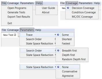
values, making the toolbox immediately ready for use upon startup. Figure 10 depicts menu options for the toolbox, listing chosen default values for the parameters and the coverage criteria.
Fig. 10. User Menu of the Toolbox
Fig. 11. Graphical Interface of the Toolbox
Use-Case Scenario 1: Basic Test Generation
A very basic use-case scenario to get started with the toolbox would consist of: 1. Opening an FBD Progam XML file (File → Open FBD Programs) 2. Generating tests (File → Generate Tests)
These actions cause the tool to attempt to generate a set of test cases that cover all of the decisions. The attempt continues until either all decisions have been covered, or the tool has run for 10 minutes even if there are decisions still uncovered. We found that pragmatically, when the toolbox is applied to FBD programs produced at Bombardier Transportation AB, the model checker has been able to generate tests in 0.05 to 133 seconds. Figure 11 depicts an output of the toolbox for this use-case scenario executed on our running example (as defined in Section 2). The figure shows several types of information presented to the user in a table with the test data (points 1,2,3 in the figure), and a set of additional information and actions (points 4, 5 and 6 in the figure). The numbered points in the figure are:
1. Steps and Timing information regarding when the specific test data is provided to the running FBD program.
2. Generated test input data needed to achieve a maximum coverage of the given program.
3. Editable area of the test output data, where the user can provide expected out-puts for a specific set of test inout-puts based on a defined behavior in the require-ment. To maintain efficient use of space in the toolbox, expected values for test outputs are provided in the form of a drop-down selection list for boolean val-ues (true/false) or as a text field for other non boolean valval-ues (integers, doubles, etc.).
4. Percentage of the logic coverage achieved by using generated tests.
5. Diagnostic information with respect to the time spent on generating tests, mem-ory usage and size of the state space.
6. Optional action to compare expected values with computed ones. Invoking the ”Validate Test Items” button causes the entries in section 3 of the test data table to be colored with green where the expected value matches the computed one, and with red where there is a mismatch. Any subsequent updates to the expected values will automatically update the coloring of that entry.
Use-Case Scenario 2: Selecting A Logic Coverage Criterion
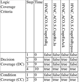
Tests generated using Use-Case Scenario 1 aim at achieving maximum decision coverage. If a user would like to use a logic coverage measurement other than the default decision coverage (DC), this can be selected from the ”Coverage” menu. Table 1 presents test inputs for the running example when the toolbox is using both decision and condition coverage. Since the running example includes a timer function block (FltDly), achieving maximum decision coverage is possible only if we provide test inputs for a certain number of time units. In the running example, the FltDly function block expects an input value to be true for at least 10 seconds. This is why inputs to the program are set to true in steps 2, 3 and 4 for decision coverage representing the state of the system at time=0, time=9 and time=10. Since there are no observable changes in the way the system behaves between time=1 and time=8, the toolbox does not display those test steps. For an industrial user, this minimization of test steps is very important, because it saves manual effort in providing expected output values for the system under test.
Table 1. Test inputs generated for Decision Coverage (DC) and Condition Coverage (CC) on the running example. In order for decisions to achieve a certain state, test inputs have to be provided for several time units due to the usage of a timer.
Logic Coverage Criteria Step Time HV A C A CO S CmprEnRq HV A C A CO S CmprRn In HV A C A CO S CmprEnAck HV A C A CO S CmprEnBypass
1 0 false false false false
Decision 2 0 true false true false
Coverage (DC) 3 9 true false true false
4 10 true true true true
Condition 1 0 false false false false
Coverage (CC) 2 0 true true true true
Use-Case Scenario 3: Changing Configuration Parameters
In addition to the basic use-case scenario of the toolbox, a user can perform various configuration changes to the way tests are obtained. This is done by modifying the model-checker’s settings in the ”Parameters” menu of the tool-box. For example, the user can set the search algorithm to be ”Breadth First”, and/or set the output trace of the model-checker to a ”Fastest” one, etc.
Use-Case Scenario 4: Fault Detection in FBD Programs
This example compares the expected values and computed values produced by the program. We created a typical fault in the Compressor Start Enable program, by removing the negated input for the AND block corresponding to the compressor running (HVAC ACO S CmprRn In). Then we generated tests that satisfy DC for both the original program (assumed to be correct) and the faulty program, as shown in Table 2 (only three signals are shown because these are the inputs that affect the output). For the original program we observe that the specification described in Section 2.2 agrees with the actual output and therefore in all cases (step 1-4) the output is green. Now by examining the output of the faulty program, the user can determine that the ventilation request is not started (HVAC ACO S CmprStaRq) when the compressor is enabled (HVAC ACO S CmprEnRq) and the compressor is
Table 2. Manual fault discovery by checking the output (no negated input signal for the AND block in Compressor Start Enable Program). When generating tests with DC for a faulty program, the Compressor Start Request signal will indicate an erroneous false status when the Compressor is not running and there is a request for enabling the compressor.
Step (number of tests) Time HV
A C A CO S CmprEnRq HV A C A CO S CmprRn In HV A C A CO S CmprStaRq
1 (Original Program) 0 false false false
2 0 true false true
3 9 true false true
4 10 true true false
1 (Faulty Program) 0 false false false
2 0 true false true
3 9 true false true
4 10 true true false
Use-Case Scenario 5: Exporting Test Results
As a final use-case scenario of the toolbox, a user can export the resulting tests in a comma separated values (CSV) format by selecting ”File → Export Test Results”. In this case, all the information from the test data table is saved, including both computed and expected (i.e., user provided) output values. Such data could be used outside of the toolbox for creation of a custom test report.
6.2 Toolbox Architecture
An overview of the toolbox architecture is presented in Figure 12. The actual toolbox was developed as a Java Swing application using the NetBeans integrated development environment and following a modular approach in the design of the toolbox architec-ture. This resulted in the following modules being part of the toolbox:
FBD Import Editor
This module is used for validating whether the structure of a provided XML file represents a valid PLCOpenXML file containing an FBD Program.
Translation Plugin
Use-case Scenarios
· Basic test generation · Select logic coverage · Configuration · Fault detection · Exporting test results
Test Report (Step) (T) (I) (O)
(1) (20s) (0, 1, 23) (1, 0)
Coverage: PC 100%
Toolbox User Interface
result import usage UPPAAL Server Trace Parser Translation Plugin FBD Import Editor UPPAAL Model Checker FBD PROGRAM FB F F command response
Fig. 12. Overview of the Toolbox Architecture.
containing the FBD Program is translated into an XML-format accepted by the UPPAAL model checker. This translation is carried out by following the rules of translation defined in Section 3.3.
UPPAAL Server
The UPPAALServer module is used for external invoking of the UPPAAL model
checker. UPPAALprovides support for formal verification using a client-server
ar-chitecture, allowing the toolbox to connect as a client to the model checker and verify properties against the model.
Trace Parser
The Trace Parser toolbox module collects diagnostic trace output from the UP
-PAALmodel checker and parses this output into a JavaCC structure corresponding
to a set of inputs and outputs for a given model. This parsing mechanism is further explained in Section 6.5.
User Interface
The function of the user interface is to provide a way for the user to communicate with the tool including: (1) the selection of which FBD program to import and generate tests for, (2) the selection of the coverage criterion to be used for test generation, (3) the presentation of generated test inputs, and (4) the determination
of correctness of the result produced for each generated test by comparing the actual test output with the expected output (as provided manually by the tool user).
6.3 PLCOpen XML Standard
The PLCOpen XML interchange format for PLC applications is the base for the model translation to timed automata. PLCOpen is a vendor independent standard aiming to provide a common programming interface for the use of the IEC 61131-3 standard. In the toolbox, the XML file used as input for the translation to timed automata is in ac-cordance to the PLCOpen standard defining the FBD programming language. Figure 13 depicts an example of a PLCOpen XML file corresponding to the Compressor Enable Program. The program consists of specific XML elements consisting of the program name (lines 5), the interface information (lines 6-20), and the block specification for AND and FltDly (lines 22-53). The XML scheme is mainly storing program informa-tion such the identifier for blocks and dependencies. As shown in Figure 13, localId indicates the identifier of a block, and every refLocalId in the connection tag repre-sents the dependency identifier for the connection to a certain block or input variables. This structural format is used in the implemented translation from FBD to timed au-tomata.
6.4 Implemented Model Translation
We define a translation inside the toolbox, which consists of the formal definition of the FBD language. A program consists of the following elements: composite programs, basic blocks, library blocks, connections, ports, and timing constraints.
The toolbox considers that each modeling element, except for the composite pro-grams, has a set of ports through which it can exchange data. Ports are associated by a set of data types, which are used for data representation, e.g., integer with a specific range. A Port is associated with the same type of data as the associated internal variable. For an FBD program the read-execute-write semantics means that input ports may only be accessed at the beginning of each computation, and output ports are only written at the end of the computation. Therefore, the behavior is augmented with an external interface. The interface of a block consists of ports and the execution order information. An input port has an associated variable holding the current data values. The internal computation of a block starts with reading all input ports. This internal data is used together with the behavioral model during execution, before writing the variables to the output ports.
We have developed the model transformation shown in Figure 14. In order to sim-plify the semantics of an FBD program, we focus on the PLCOpen language constructs relevant to functional and timing modeling elements.
The PLCOpen language is implemented as an XML profile that provides the abil-ity to describe FBD programs using this profile. The PLCOpen language provides both structural and graphical information needed for implementing the actual translation. The toolbox generates PLCOpen files in an XML format. As shown in Figure 14, we
introduce the timed automata as the interface between the FBD program and the UP
1 <? xml v e r s i o n = " 1 . 0 " e n c o d i n g =" UTF -8" ?> 2 <p r o j e c t x m l n s =" www . p l c o p e n . org / xml / tc6 . xsd "> 3 <t y p e s> <d a t a T y p e s/ > 4 <p o u s> 5 <pou n a m e =" H V A C _ A C O _ C m p r E n " p o u T y p e =" f B l o c k "> 6 <i n t e r f a c e> 7 <i n p u t V a r s r e t a i n =" f a l s e "> 8 <v a r i a b l e n a m e =" H V A C _ A C O _ S _ C m p r E n R q "> 9 <t y p e> <B O O L/ > < /t y p e> 10 < /v a r i a b l e> 11 <v a r i a b l e n a m e =" H V A C _ A C O _ S C m p r R n I n "> 12 <t y p e> <B O O L/ > < /t y p e> 13 < /v a r i a b l e> 14 < /i n p u t V a r s> 15 <o u t p u t V a r s r e t a i n =" f a l s e "> 16 <v a r i a b l e n a m e =" H V A C _ A C O _ C _ C m p r S t a E n "> 17 <t y p e> <B O O L/ > < /t y p e> 18 < /v a r i a b l e> 19 < /o u t p u t V a r s> 20 < /i n t e r f a c e> 21 <b o d y> <FBD> 22 <b l o c k t y p e N a m e =" AND " l o c a l I d =" 11 "> 23 <i n p u t V a r i a b l e s> 24 <v a r i a b l e f o r m a l P a r a m e t e r =" IN1 " 25 n e g a t e d =" t r u e "> 26 <c o n n e c t i o n r e f L o c a l I d =" 14 "> < /c o n n e c t i o n> 27 < /v a r i a b l e> 28 <v a r i a b l e f o r m a l P a r a m e t e r =" IN2 " 29 h i d d e n =" t r u e "> 30 <c o n n e c t i o n r e f L o c a l I d =" 13 "> < /c o n n e c t i o n> 31 < /v a r i a b l e> 32 < /i n p u t V a r i a b l e s> 33 <i n O u t V a r i a b l e s/ > 34 <o u t p u t V a r i a b l e s> 35 <v a r i a b l e f o r m a l P a r a m e t e r =" OUT " 36 h i d d e n =" t r u e "> 37 < /v a r i a b l e> 38 < /o u t p u t V a r i a b l e s> 39 < /b l o c k> 40 <b l o c k t y p e N a m e =" F l t D l y " l o c a l I d =" 66 "> 41 <i n p u t V a r i a b l e s> 42 <v a r i a b l e f o r m a l P a r a m e t e r =" IN "> 43 <c o n n e c t i o n r e f L o c a l I d =" 18 " 44 f o r m a l P a r a m e t e r =" OUT "> 45 < /c o n n e c t i o n> 46 < /v a r i a b l e> 47 <v a r i a b l e f o r m a l P a r a m e t e r =" PT "> 48 <c o n n e c t i o n r e f L o c a l I d =" 21 "/ > 49 < /v a r i a b l e> 50 <v a r i a b l e f o r m a l P a r a m e t e r =" E N A B L E "> 51 <c o n n e c t i o n r e f L o c a l I d =" 22 "/ > 52 < /v a r i a b l e> 53 < /i n p u t V a r i a b l e s> 54 <i n O u t V a r i a b l e s/ > 55 <o u t p u t V a r i a b l e s> 56 <v a r i a b l e f o r m a l P a r a m e t e r =" FLT "> < /v a r i a b l e> 57 <v a r i a b l e f o r m a l P a r a m e t e r =" BLK "> < /v a r i a b l e> 58 < /o u t p u t V a r i a b l e s> 59 < /b l o c k> 60 < /FBD> < /b o d y> 61 < /pou> 62 < /p o u s> 63 < /t y p e s> 64 <i n s t a n c e s> <c o n f i g u r a t i o n s/ > < /i n s t a n c e s> 65 < /p r o j e c t>
Compresor Start Enable Program Timed Automata Metamodel FB F F FBD PLCOpen Profile + Metamodel Compresor Start Enable Timed Automata UPPAAL input file conforms conforms Model-to-Model Model-to-Text
Fig. 14. Model Export from an FBD Program to UPPAAl Model Checker.
profile and meta-model. The structural translation described in Section 3.3 maps an FBD program into timed automata. The structure of the timed automata model is the
basis of the model to text transformation into the UPPAALinput model.
FBD Composition Type Execution Order Block Port Conn2Port Model Id Connection connects 0..* compose 0..* offer 0..* behavior 0..* source 1..1 destination 1..1
Fig. 15. Class Diagram representing the meta-model elements of the Function Block Diagram.
The modeling elements of an FBD program used in the translation are described in Figure 15. These elements represent the structure of the model, the behavior, and the timing information. The meta-model elements provide concepts used in component
based design. A Block element can be translated with Type, ExecutionOrder and Model elements. Blocks can be composed using connections and ports. Furthermore, a Block element can have a behavioral description as a Model element. The model provided after the translation represents the model annotated with triggering and timing information with assumed functionality.
6.5 Dynamic Traces - JavaCC - Test Cases
1 S t a t e 2 ( 3 plc . E x e c u t e P r o g r a m r e a d i n p u t 1 . P r o c e s s 4 r e a d i n p u t 2 . _ i d 1 0 r e a d i n p u t 3 . P r o c e s s 5 r e a d i n p u t 4 . _ i d 1 2 a n d 1 . U p d a t e 6 a n d 2 . _ i d 1 8 f l t d l y 1 . W a i t i n g 7 s e l 1 . _ i d 1 5 m o v e 1 . _ i d 1 6 8 w r i t e o u t p u t 1 . _ i d 5 w r i t e o u t p u t 2 . _ i d 6 9 w r i t e o u t p u t 3 . _ i d 7 w r i t e o u t p u t 4 . _ i d 8 10 ) 11 12 f l t d l y 1 . ET <=0 s t e p s =1 H V A C _ A C O _ S _ C m p r E n R q =1 13 H V A C _ A C O _ S _ C m p r R n _ I n =1 H V A C _ A C O _ S _ C m p r E n A c k =0 14 H V A C _ A C O _ S _ C m p r E n B y p a s s =1 H V A C _ A C O _ C _ C m p r S t a E n =0 15 H V A C _ A C O _ S _ C m p r S t a R q =0 H V A C _ A C O _ S _ C m p r R n =0 16 H V A C _ A C O _ E _ C m p r R n =0 17 18 A N D 1 =0 A N D 2 =0 F l t D l y 1 =0 S E L 1 =0 M O V E 1 =0 19 20 N =1 IN =5 OUT =1 21 22 d e c i s i o n s [ 0 ] = 0 d e c i s i o n s [ 1 ] = 0 d e c i s i o n s [ 2 ] = 0 23 d e c i s i o n s [ 3 ] = 0 d e c i s i o n s [ 4 ] = 0 d e c i s i o n s [ 5 ] = 0 24 d e c i s i o n s [ 6 ] = 0 d e c i s i o n s [ 7 ] = 0 d e c i s i o n s [ 8 ] = 0 25 d e c i s i o n s [ 9 ] = 0 26 27 f l t d l y 1 . c o u n t e r =0 m o v e 1 . f i r s t T i m e =0 28 m o v e 1 . R S _ l o c a l =0 m o v e 1 . d e c i s i o n =0 29 30 T r a n s i t i o n s : 31 plc . E x e c u t e P r o g r a m - > plc . U p d a t e O u t p u t s 32 { IN == I n p u t V a r i a b l e s , e x e c u t e ! , 1 } 33 34 a n d 1 . Update - > a n d 1 . U p d a t e 35 { !( H V A C _ A C O _ S _ C m p r E n A c k && H V A C _ A C O _ S _ C m p r E n R q ) && 36 N == 1 , e x e c u t e ? , A N D 1 := 0 , N ++ , d e c i s i o n s [0] := 1 37 }
Fig. 16. An excerpt of a trace in response to a command to UPPAAL for the Compressor Enable Program.
UPPAALmodel-checking tool is mainly used for the verification of a certain prop-erty of a model, resulting in a affirmative or a negative response. However, it is also possible to obtain a full trace used in the process of verifying that property on a model. An excerpt of such a trace for the running example is shown in Figure 16. To interpret
dynamic traces generated by UPPAAL, a grammar file was created for JavaCC7parser generator. The trace starts with the initial state and is followed by pairs of transitions and states, i.e. the state can be reached from the previous state via the transition. A state in the trace contains locations (lines 3-9), clocks (line 12), internal variables (lines 12-20), decisions and conditions (lines 22-25) in the same order as they appear in the UPPAALinput file. The trace parsing using JavaCC is the process of analyzing the trace, transforming the trace into a state machine, extracting the necessary information (i.e., values of the input and output variables, clock valuation) needed for testing of an FBD program. In the end tests are merged based on the program cycle scan as one or more test cases separated by resets.
7
Experimental Evaluation and Discussions
Our goal in this section is to evaluate the toolbox on industrial FBD programs and to acquire experience regarding its efficiency and usability. We therefore conduct a set of analyses using programs developed by Bombardier Transportation AB in Sweden. The system has been in development for more than two years and uses processes influ-enced by safety-critical requirements and regulations including the EN 50128 standard [8] which requires different logic coverage levels (e.g., DC and MC/DC). In 2014 its source code was made up of more than 350.000 lines of C code generated from FBD programs. The development teams use both automated and manual testing from unit testing through system testing.
Table 3. Information about the 157 subject programs. Blocks Inputs Outputs Decisions
Maximum per Program 32 15 29 196
Average per Program 6.9 2.7 5.9 30
We investigate the following questions regarding the tool’s performance:
– Q1, Efficiency: What is the time required for the tool to generate tests that satisfy the DC, CC and MC/DC logic coverage criteria?
– Q2, Coverage: How close does the tool come to generating tests that achieve 100% coverage of each of the criteria?
The industrial system studied in this paper is the TCMS (Train Control and Manage-ment System), developed by Bombardier Transportation AB engineers, which has been deployed to the field. In this research we, have used all TCMS programs written in the FBD standard language resulting in a total of 157 artifacts. Each of the programs is siz-able and representative of industrial programs used in the train system’s development. Information regarding the size of the system and number of blocks is provided in Table 3.
For each program, the tool generated a model version in UPPAAL. Then, for each implementation of a program, the toolbox:
– Generated test input vectors for three different coverage criteria. We used a reachability-based approach for generation of tests aimed at satisfying DC, CC and MC/DC. If the model checker is able to find a path to satisfy a reachability property, given that such a path exists, then the approach is guaranteed to generate a test suite that achieves maximum possible coverage of the program.
Table 4. Average, median, minimum, and maximum generation times for 123 of the 157 pro-grams.
CC MC/DC DC
Average Generation Time (s) 1.53 4.54 1.93
Median Generation Time (s) 0.27 0.51 0.34
Minimum Generation Time (s) 0.05 0.06 0.06
Maximum Generation Time (s) 35.37 133.60 72.125
Hence, if the model checker succeeds in finding paths to satisfy all the reachability properties for a given criterion, then the method will achieve 100% coverage for
that criterion. We have used the UPPAALmodel checker in our experiments. Our
reachability-based test generation approach produces one test for each coverage criterion as our goal is to assess the coverage and efficiency of the toolbox in terms of time to generate tests. To generate the tests, the tool uses the random-depth first
search algorithm provided by the UPPAALmodel checker. The tool terminates the
generation by determining the coverage requirements satisfied by each test. – Assessed efficiency of each test based on coverage, and collected complexity
mea-sures for each program.We measured the generation time for each program and
determined the number of test requirements for each coverage criterion.
To answer Q1 and Q2, the tool generate tests aimed at achieving maximum logic coverage. Since we are using a model checker for generating tests, the toolbox simply produces the maximum achievable coverage with a proof that uncovered test obliga-tions are not coverable. For 123 of the 157 programs (78%) the tool provided tests that covered 100% of the required entities for each of the three coverage criteria. Table 4 gives the performance figures in terms of time needed to generate the tests. The gener-ation time for MC/DC averaged approximately twice as long as for DC. The results are summarized as boxplots in Figure 17 with the kernel density distribution of the gener-ation time shown in Figure 18. The kernel densities estimates for the genergener-ation time for DC (red), CC (green) and MC/DC (blue) are plotted on the same graph. It is quite clear on the graph that the distribution of generation times is more variable for MC/DC. It is also worth noting that the generation time modes (i.e., most frequent values in the generation time data set) of a distribution are close to each other for all criteria. We can observe that a few outliers caused the average generation time to greatly exceed the median generation time for all coverage criteria.
CC MC/DC DC 0 1 2 3 4 5 Coverage Type G e n e ra ti o n T ime
Fig. 17. Experimental results: Generation Time Distributions.
0 1 2 3 4 5 0.0 0.2 0.4 0.6 0.8 1.0 1.2 Generation Time Density
Type of Coverage Criteria DC CC MC/DC
Fig. 18. Generation Time Distribution by Coverage Criteria.
For 34 of the 157 programs, the tool did not terminate after running for a substantial period of time. After discussions with engineers from Bombardier Transportation AB regarding the needed time for a tester to provide a set of tests for a desired coverage,
we concluded that 10 minutes was a reasonable cut-off point for the model checker to terminate its search. Recall, however, that the aim of these experiments was not to provide measures of test effectiveness in the sense of bug-finding, but instead to evaluate the applicability of using a model checking technique for test generation and its success in meeting coverage requirements. We wanted to work with a realistic cut-off time that could be used in practice if this approach is to be adopted. Therefore, in each case a run of the model checker was terminated after 10 minutes.
Table 5. Achieved coverage for all Programs.
Case 1 2
Percentage of all Programs 78% 22%
Average DC Achieved 100% 82%
Average CC Achieved 100% 88%
Average MC/DC Achieved 100% 65%
As noted above, for 22% of the programs in this study, the tool did not generate the required test suite in an acceptable period of time. To determine the circumstances under which the toolbox does or does not successfully generate test suites that satisfy one of the logic coverage criteria (Q2) we collected the average number of decisions for both the case when the model checker finishes its execution (Case 1) and the case when we forcefully terminated the tool because the running time reached 10 minutes (Case 2). Table 5 provides information about these two cases. Case 1 consists of the 78% for which the tool generated tests achieving 100% DC, CC and MC/DC. The number of decisions for Case 1 ranged from 1 to 22 with the average being 5. In contrast, for Case 2, the set of programs for which the tool exceeds the allocated time before generating a test set satisfying the coverage criterion, the decisions ranged from 12 to 196 with the average being 38. This indicates that as the number of decisions increases, the performance deteriorates and the cost of using the tool may become prohibitive. This factor contributes to a scalability issue which results in longer test sequences, especially when generating tests for MC/DC.
It is important to note that during model-checking the reachability-based genera-tion used by the toolbox is guided to achieve a desired coverage, and not to minimize or optimize the test. A generated test may not be the minimal way to satisfy the cov-erage criterion. However, a generated test might be able to satisfy more than one test obligation. From the point of view of limiting the number of tests generated, we note that our approach would perform better than other approaches including trap property generation [25, 14], which can lead to a large number of duplicate tests because these properties are derived by using the model-checker’s ability to generate counterexam-ples.
Engineers from Bombardier Transportation AB indicated that their certification cess involves achieving a minimum of 80% DC for all programs. For 78% of the pro-grams in this study, the tool automatically generated tests achieving 100% DC, CC and MC/DC. For the other 22% of the programs, the results were less satisfactory. The data
about the achieved coverage is shown in Table 5. As can be seen from this data, the tool generated tests with 82% DC on average. We conclude that we have provided evidence that this is a suitable tool for test generation tailored to FBD programs; it scaled well for most of the programs in this study and it is fully automated. There are, however, some drawbacks. Most importantly, for 22% of the programs, even though the tests gener-ated for the coverage criteria achieved on average at least 65% coverage, we cannot determine whether the remaining test requirements are actually achievable, or if tests satisfying the requirements are longer that the search depth. This is an issue particularly for MC/DC where a fair number of test obligations were not satisfied.
From these experiments, it is clear that the toolbox can be sensitive to the number of decisions and as a consequence to the length of the tests required to achieve the desired coverage. In addition, the number of inputs considered during model checking is affecting the efficiency of the test generation technique. However, model checking does allow one to use a heuristic or meta-heuristic search technique [6, 26] to find the desired tests. We plan to investigate this approach in future work. In addition, the idea of combining symbolic execution or static analysis with model checking to achieve test generation has been proposed [20], and may allow more efficient model checking. Fraser et al. [13] noted that there is a lack of empirical evidence on how these model-checking techniques compare to each other in practice, making it hard to select an appropriate technique for a specific test purpose. We also plan to investigate how various approaches compare in future work.
8
Related Work
Model checkers have been used to produce test cases satisfying various criteria and for programs in a variety of formal languages [7, 17, 11]. Black et al. [4] discuss the prob-lems encountered in using a model-checker for test case generation for full-predicate coverage. They present reasons why model-checking is not directly applicable for gen-erating tests to satisfy logic coverage criteria. In our previous work [12], we overcome this issue by providing a way of generating test cases for logic criteria that are directly applicable to FBD programs. We found that model-checkers are an appropriate tech-nique for automated test generation in terms of performance when used on real-world programs.
For data-flow programming languages such as FBD and Lustre, which describe the relationship between inputs and outputs instead of the control flow of the program, researchers proposed specific coverage metrics based on the structural aspects of the programs [19, 18, 21]. For Lustre, structural coverage metrics are based on the activation condition concept of the language that can be used when data travels from an input edge to an output edge. In addition, Whalen et al. [28] defined an alternative approach to measuring logic coverage for data flow programs called OMC/DC, a combination of MC/DC and an additional obligation to be satisfied such that faults will be observed through a variable monitored by the criteria.