IN
DEGREE PROJECT TECHNOLOGY, FIRST CYCLE, 15 CREDITS
,
STOCKHOLM SWEDEN 2016
Human controlled robotic
arm
Improving usability with haptic feedback
SIMON AHLIN HÖGFELDT
Human controlled robotic arm
SIMON AHLIN HÖGFELDT DANIEL SÖDERMAN
Bacherlor’s Thesis in Mechatronics Supervisor: Fariba Rahimi
Examiner: Martin Edin Grimheden Approved: 2016-06-07
Abstract
In our modern society, the usage of robotic arms are increasing. Much of the work in the industry is now done by robots. Even though they are able to do very precise work, difficulties appear when trying to do some of the tasks that humans do. This can be changed by making it easy for a human to control the robotic arm and to "teach it" how it’s done.
The purpose of this project is to develop a robotic arm that is easily con-trolled by the user. This is done by using the users own arm movement to control the robot. To make the usage more intuitive, a simple haptic feedback system will be implemented. This creates a greater experience where the user is able to "feel what the robot feels". To be able to create such a system, development of an easy control unit, robotic arm and feedback system has to be made. The steering of the robotic arm is created from reading the user’s arm movement with potentiometers, and mapping these values to servos on the robotic arm. Sensors on the robotic claw and on the user’s hand makes it possible for a DC motor to create a counter torque that gives a feel for the size of the object being lifted.
The feedback system seemed to improve the overall experience of using a robotic arm and with further work, today’s robotic industry could be improved.
Sammanfattning
Robotarm styrd av människans arm
Allt mer arbete inom industrin utförs av robotarmar. Fördelen är att de klarar av att utföra arbeten med hög precision. Däremot finns det problematik då robotar ska utföra vissa specifika arbeten som människor utför. Genom att på ett enkelt sätt kunna styra en robotarm med sin egen armrörelse skulle användaren enkelt kunna lära roboten att göra de rörelser som annars varit svåra att programmera för dess rörelsemönster.
Syftet med detta projekt är att utveckla en robotarm som underlättar sty-randet. För att göra detta till en mer naturlig upplevelse, implemeteras ett feed-backsystem som gör att användare i viss mån kan "känna vad roboten känner". För att kunna skapa ett sådant system behövdes en robotarm, en styrenhet och ett feedbacksystem utvecklas. Robotarmen styrs genom att potentiomet-rar registrepotentiomet-rar användarens rörelse. Dessa värden från potentiometpotentiomet-rarna skickas sedan till servomotorer som styr robotarmen. Kraftsensorer på robotklon och användarens egen hand tillåter oss att styra en DC motor som kan tillföra ett visst moment till användarens hand. Detta gör att man kan känna ungefärlig storlek på det objekt som robotarmen greppar.
Feedbacksystemet verkade förbättra användandet av robotarmen. Med fram-tida utveckling av detta projekt skulle framtidens robotindustri kunna förbätt-ras avsevärt.
Preface
We would like to thank our class mates for all the helpful and valuable discussions. Staffan Qvarnström provided us with the electronic parts needed. Tomas Östberg for providing us with the tools needed for the construction. Fariba Rahimi for help with the project and PID control.
Daniel Söderman, Simon Ahlin Högfeldt, Stockholm, May, 2016
Contents
Abstract iii Sammanfattning v Preface vii Contents ix Nomenclature xi 1 Introduction 1 1.1 Background . . . 1 1.2 Purpose . . . 2 1.3 Scope . . . 2 1.4 Method . . . 3 1.4.1 Haptic feedback . . . 3 1.4.2 Robotic arm . . . 3 1.4.3 Arm unit . . . 41.4.4 Measuring the real step response . . . 4
1.4.5 Application testing . . . 4 2 Theory 5 2.1 Past Research . . . 5 2.2 PID-control . . . 5 3 Demonstrator 7 3.1 Problem formulation . . . 7 3.2 Hardware . . . 8 3.2.1 Chosen parts . . . 8 3.2.2 Robotic arm . . . 8 3.2.3 Arm unit . . . 11 3.3 Electronics . . . 14 3.4 Software . . . 16
3.5 Measuring step response . . . 17
3.6 Application testing . . . 19
3.7 Results . . . 19
3.7.1 PID . . . 20
3.7.2 Application testing . . . 22
4 Discussion and conclusions 23 4.1 Discussion . . . 23
4.2 Conclusions . . . 25
5 Recommendations and future work 27 5.1 Recommendations . . . 27 5.2 Future work . . . 27 Bibliography 29 Appendices A Datasheets 31 B Schematics 37 C Arduino Code 39 D Matlab Code 49 E Plots 57
Nomenclature
Symbols
Symbols Description
P Proportional part parameter
I Integral part parameter
D Derivative part parameter
J Rotor inertia [kg·m2]
b Motor viscous friction constant [N·m·s]
K Torque constant [Nm/A]
R Electric resistance [Ω]
L Electric inductance [H]
Gmotor Transfer function for DC motor
F Transfer function for controller
Abbreviations
Abbreviation Description
FSR Force Sensitive Resistor
PID controller Proportional–Integral–Derivative controller
DC motor Direct Current motor
CAD Computer Aided Design
Chapter 1
Introduction
1.1
Background
In our modern society, the development of technological solutions has been in great focus. Robotic arms has revolutionized the industry by making it more cost ef-ficient, improving build quality, decreasing production time.[Keystone Electronics Corp, 2013] In the future, robotic arms will be even more important in manufactur-ing.[HAGERTY, 2015] At BMW there are robots doing the big jobs of fastening the body panels and doing the welding. However what remains is to use those robots on the assembly line where workers assemble the more complex parts.[IndustryWeek, 2012] Robotic arms are improving and the precision required for assembly may be achieved. But to control the movement of the robotic arm, an engineer is often required to program its software. A way to make robotic arms easier to control is to allow the robotic arm to be controlled by the user’s own arm.
You could almost say that we have mastered the technique of controlling our own arm movement. Because a robotic arm’s construction is similar to the human arm, it makes sense for the user to control it with her own arm. This would make it easy to understand its movement limitations.
When you move your own arm you get feedback as to what the arm is experi-encing. Without some type of feedback the feeling of controlling the robotic arm is diminished. For full control of the robotic arm some type of force feedback would be helpful.
Research into robotic arms with feedback can often be seen in the surgical in-dustry. However these are often built with a narrow purpose in mind and are also very expensive since surgical precision is needed.[Okamura, 2009] This project ex-plores cheaper and simpler options that don’t have to follow the same standard as the medical industry.
CHAPTER 1. INTRODUCTION
1.2
Purpose
The purpose of this project is to improve the application of a standard robotic arm by implementing a control of the robotic arm with an arm unit that follows your arm’s movement. Simple haptic feedback will be implemented that transmits the force that the robotic arm is feeling back to your own hand that is connected to the arm unit. It should be possible for a person without any knowledge about robotic control to be able to control the robotic arm’s movement. This means that the controller should be made in an intuitive way i.e controlling it with your own arm. The haptic feedback will be constructed using a force sensor on the robotic arm’s claw and one on the arm unit. By implementing a motor on the arm unit, the force that the user feels in their hand can be altered to be equal to the force that is measured at the gripping claw. This requires an optimized PID controller. The system leads to the interesting question on how the real system differs from the theoretical calculations. Therefore, comparison of the step response for the real system and the one in theory will be done.
The research questions of this study are:
• "Which PID control parameters fits better to the designed system with feed-back?"
• "How does the feedback system differ to the simulated model?"
• "How will the implemented haptic feedback affect the application of the robotic arm?"
1.3
Scope
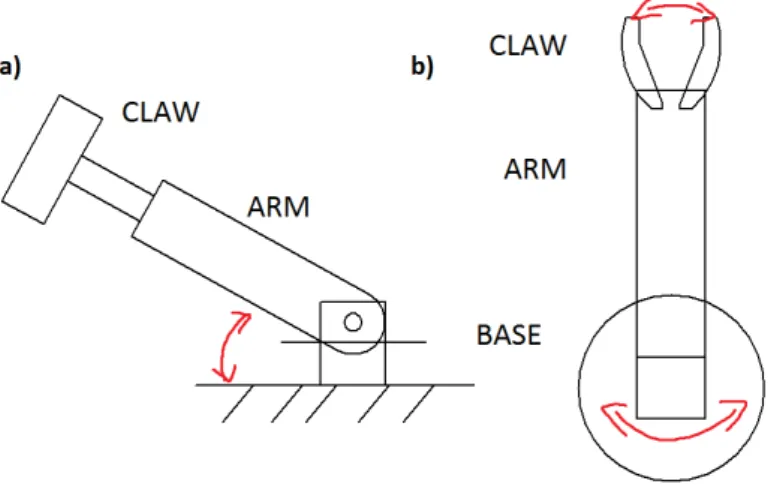
This report covers a semester work for a Bachelors thesis at KTH with limited time and resources. Due to this, there must be some limitations to the construction. Focus will be on the haptic feedback and its functionality. The construction of the robotic arm and arm unit will therefore be as simplified as possible. The main goal for the robotic arm is to be able to grip an object and move it. The weight of the object and the distance is not important as this does not affect the main purpose of this project. Limitations of the robotic arm and arm unit is set to three degrees of freedom as shown in Figure 1.1. The feedback system will affect the whole hand and will not be different for the separate fingers. This means that the robotic claw will be a single flat surface, corresponding to a human hand with all their fingers closed together. The robotic arm will only be able to grab objects with simple rectangular shapes. When calculating the transfer function for the PID controller, some frictions will be neglected. Due to the fact that the purpose of the units are for scientific testing, the appearance and practical use is not in focus.
1.4. METHOD
Figure 1.1. Sketch showing the degrees of freedom. a) Side view where upwards
rotation is shown. b) View from above where the opening and closing of the claw as well as the horizontal rotation of the base is shown.
1.4
Method
1.4.1 Haptic feedback
The main goal of the design is that the user should be able to feel when the robotic arm grabs an object. A general feel of the object size should also be possible. For this, the robotic arm should be able to register the normal force from the object being grabbed. The same force should occur on the user’s hand. The arm unit therefore needs to register the force between the user’s hand and the unit. This is done by using a FSR on the robotic arm’s claw and one FSR on the arm unit. For the user to be able to feel the same force as the robotic arm, the signal from each FSR should be the same.
1.4.2 Robotic arm
The robotic arm is constructed with some simplifications. Most of its parts are 3D printed using a Ultimaker,[Ultimaker BV, 2016]. The less complex parts are created in wood using a laser printer Epson,[Epilog Laser, 2016]. For reducing the errors during the construction, most parts has been modeled using Solidedge,[Siemens PLM Software, 2016]. To make the controlling of the arm as intuitive as possible, the robotic arm should have the same limitations as a human arm, i.e the same degrees of freedom. The movement of the robotic arm is created using three servos, one for each degree of freedom, see Figure 1.1. The claw will be built as plates, therefore it will be hard to grab circular objects.
CHAPTER 1. INTRODUCTION 1.4.3 Arm unit
Because of its simple design, the arm unit is mostly created in wood using a laser printer Epson,[Epilog Laser, 2016]. The movement is registered using three poten-tiometers, one for each degree of freedom. These should correspond to the same degrees as on the robotic arm, see Figure 1.1. Using the signal from the poten-tiometers, the angles can be calculated. Knowing this angle, the same angle can be sent to the servo on the robotic arm. A DC motor is used to create the counter torque needed on the user’s hand. This torque makes the user feel a force, thus the value of the FSR will increase. This enables us to create a simple feedback system, where the signal to the motor is controlled to give different torques depending on how hard the robotic arm is grabbing an object.
1.4.4 Measuring the real step response
To get a measurement of the real step response, a real test was made. The test was conducted by having the user’s hand connected to the arm unit. The robotic arm was then given a predefined force. The feedback system will then try to get the value of the FSR on the arm unit to be the same as on the robotic arm. This is done via the DC motor mounted on the arm unit. By saving the values of the arm unit’s FSR during this procedure, the step response of the real system could be plotted.
1.4.5 Application testing
An interesting aspect of the haptic feedback system is how it affects the application for the user. To answer this question, a small amount of test subjects did multiple predefined tasks and then answered some questions about the application with the feedback system.
Chapter 2
Theory
2.1
Past Research
There have been projects where the robotic arm is controlled by the human arm. One uses accelometers to register the movement of the human arm. [PATTNAIK, 2013]. Another solution is to use gyroscopes and bendable potentiometers[bluebean, 2012]. These methods are unnecessarily complex where some sort of filter is needed. The signal from a potentiometer is stable and will provide for easier control with less fluctuations. Therefore simple potentiometers will be used for registering the movement of the user.
2.2
PID-control
For a system to be able to read a reference value and then do something to make the system get to that value, the system needs to continuously calculate an error value. This is the difference between the desired value and the measured value. The system will then try to minimize this error over time by adjusting the system. The PID controller is made up of three parts. The proportional (P) part corresponds to the gain of the controller. If this part is increased the system gets a faster response at the cost of stability. Using only a P-controller has some drawbacks. The error will always be greater than zero. For a fast system (where the proportional constant value is high) the system will get large overshoots. Overshoot is when the system exceeds its final steady-state value. To overcome this problem, an integral part (I) needs to be implemented. Increasing the I part yields a smaller steady state error but once again at the cost of reduced stability. Adding a derivative part (D) part is used for better stability. An increased D gives greater stability. [Glad and Ljung, 2006] To apply this controller to a DC motor, the transfer function from voltage to speed in the laplace domain must be known. This is received from [Univeristy of Michigan, 2016]
CHAPTER 2. THEORY
Gmotor =
K
((J·s + b)·(L·s + R) + K2). (2.1)
Equation 2.1 does not consider friction forces. It only consider the DC motor. The system is now mathematically expressed and can be simulated using MATLAB simulink,[MathWorks Nordic, 2015b]. This makes the closed loop system
F ·Gmotor
1 + F ·Gmotor
. (2.2)
Where F is the PI or PID controller in laplace domain. The PI controller is written in laplace domain as
F = P s+ I
s . (2.3)
The PID controller can be written as F = P s+ Ds
2+ I
s . (2.4)
For tuning the controller, pole placement is used. This is done by placing the poles of the denominator of (2.2) and solving for the P,I, and D part. The closed loop system will be of second order and have two poles. Which gives the following equation for the P,I,and D parameters
(s + pole)2 = 1 + F ·G
motor. (2.5)
Note that one or more of the parameters P, I and D can be set to zero. This gives different controllers, such as P, PI, PD and PID. Using the step response, the parameters of the controller can be tuned to give a desirable behavior.
Chapter 3
Demonstrator
3.1
Problem formulation
The robotic system can be divided into two major parts, the arm unit and the robotic arm. The arm unit will read the human arm movement. The robotic arm is the robot itself, which will do the movement given by the user. Each system requires a number of technical solutions. The requirements for the arm unit are:
• Easy to fasten user’s arm. • Intuitive to use.
• Read the movement with potentiometers. • Read the normal force created from a motor. • Transfer torque from DC motor to user’s hand. The requirements for the robotic arm are:
• Movement created by servos.
• Create same movement as read by the arm unit. • Able to lift and move objects.
• Read the normal force of grabbed object.
To be able to create the correct counter torque from the motor on the user’s hand, a PID controller needs to be implemented. The problem to be solved is to optimize the values of the controller’s constants, but also to see what kind of controller is best for our purpose. To be able to optimize the PID, a set of requirements needs to be decided for the system. The requirements for the PID controller are:
• Stable system.
• Small to no overshoot.
CHAPTER 3. DEMONSTRATOR
3.2
Hardware
3.2.1 Chosen parts
These are the chosen parts for our prototype. • 3 Servos (Parallax Standard Servo 900-00005) • 1 Motor (Maxon motor 110147 with gears 232766) • H-bridge (L298)
• 2 FSR (Interlink 402)
• 3 Potentiometers 10KΩ (PIHER PC16SH10IP06-103A2020–TA)
When deciding which servos to buy, small servos was preferred, while being strong enough for lifting objects. The robot should be able to lift 0.5 kilograms. The servo’s strength is given in torque. To choose an appropriate servo, a simple calculation for the required torque was made. The largest strain is for the lifting movement. The distance from the servos rotational center point to the end of the gripping claw is approximately 0.35m. The weight of the arm and claw itself is approximately 0.2kg Lifting a weight of 0.5kg would require a torque of approximately
(0.5 + 0.2)·0.35 = 0.245Nm. (3.1)
As mentioned above, the chosen servo should be able to create a torque of approximately 0.26 Nm.
For the haptic feedback a DC motor was chosen because it is easy to control speed and torque compared to servos or stepper motors. When choosing the motor, the strength and required speed was unknown. The feedback system was built and the DC motor was chosen with trial and error. One important aspect was that the motor should not be too heavy. This would make the whole arm unit heavy and hard to use for the user. The motor mentioned above was both strong and fast enough to fulfill the requirements for the feedback system and was of a reasonable size.
The H-bridge was chosen with simplicity in mind. The component had to be easy to use, cheap and available. The purpose is to be able to control a DC motor. The FSR needed to be cheap but reliable with good accuracy. The chosen FSR fulfilled these requirements. They were also easy to fastened.
Potentiometers were chosen to track the arm movement because they provide a logical connection with the angles of the servos. The resistance of 10KΩ is chosen to provide a more stable signal.
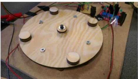
3.2.2 Robotic arm
The construction of the robotic arm uses a combination of 3D printing and laser cutting. The base is 3D printed to fit one servo. Its main purpose is to rotate the
3.2. HARDWARE
whole robotic arm. Wooden feet were laser cut and mounted to the base, see Figure 3.1.
Figure 3.1. The base of the robotic arm. Servo is mounted and fastened with four
bolts.
The servo mounted in the base is connected to another housing. The torque is transferred via a connection to the servo arm. This is the part being horizontally rotated, see Figure 3.2.
Figure 3.2. The rotational part of the robotic arm mounted on the base. Torque is
transferred via a tight fitting shape around the servo arm.
The second servo takes care of the second degree of freedom, which is lifting the arm vertically. This servo is mounted in the mentioned housing, see Figure 3.3. On this part, two wooden arms are connected via an attachment part. This part is a 3D printed U-shaped part that connects the two wooden arms to the servo. A similar connection to the servo arm is implemented for transferring its torque.
CHAPTER 3. DEMONSTRATOR
Figure 3.3. The arm part is mounted via a 3D printed U-shape connector. This
connects to the servo and transfers the torque. The servo is fastened with four bolts.
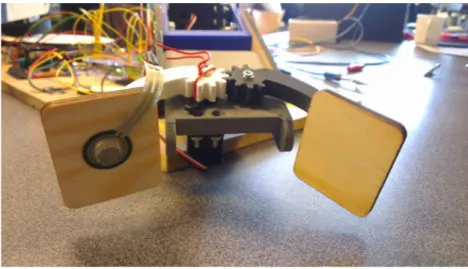
The wooden arm parts are attached to a 3D printed claw connector. The third servo is fastened underneath this connector, see Figure 3.4. The claws are 3D printed with the gears designed to create movement in both claw parts with only one servo. For a claw with a bigger surface area, sheets of wood were laser cut as the final piece of the claw for better grip. A FSR is mounted on one of the wooden pieces. This will sense the force on the robotic arm.
Figure 3.4. The claw connected to the servo. It is fastened to the servo with a
screw. The rotational movement transfers to the other claw via gears. The claws are 3D printed. The gripping part is made out of wooden pieces. A FSR is mounted on one of the plates.
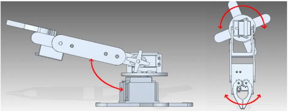
The complete robotic arm, see Figure 3.5, is a result of solutions for transferring the torques from the three servos. It uses a total of three servos, one for each degree of freedom, see Figure 3.6.
3.2. HARDWARE
Figure 3.5. The final version of the robotic arm
Figure 3.6. The movements of the robotic arm with three degrees of freedom
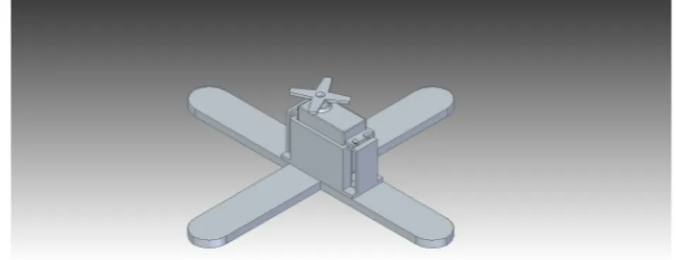
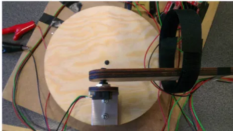
3.2.3 Arm unit
The arm unit is constructed by sheet wood which has been laser cut using CAD designs. There are three major parts, as seen in Figure 3.7. One part for each degree of freedom with potentiometers paired with each servo.
CHAPTER 3. DEMONSTRATOR
Figure 3.7. An overview of the arm unit.
The function of the base is to follow the user’s horizontal rotation of the arm. This is registered by a potentiometer. Its shaft is mounted to the rotational plate. The potentiometer itself is fastened to another plate underneath the rotational plate, see Figure 3.8. For stability this part has circular stands attached.
Figure 3.8. The potentiometer for measuring the horizontal rotation is fastened
underneath the rotational plate
The user’s arm is fastened to a long wooden piece that connects the rotational base to the hand part. This piece is connected to a potentiometer that reads the rotation from lifting the hand, see Figure 3.9.
3.2. HARDWARE
Figure 3.9. The potentiometer is fastened via a bend metal piece. It registers the
rotation of the vertical movement of the arm.
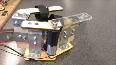
The hand part is a complex system that was built as the project progressed. The hand piece has two major functions. It measures how the user opens and closes her hand and transfers the torque produced by a mounted DC motor. The measuring of the user’s hand movement is done with a potentiometer, see Figure 3.10.
Figure 3.10. The potentiometer is fastened to the wooden piece at the bottom.
This piece is fastened to a metal plate which is fastened to the rigid part of the hand unit. A similar part is connected to the potentiometer shaft, but connected to the outer part of the hand unit.
The haptic feedback is constructed by fastening the DC motor to the rigid part of the hand. The motor shaft is coupled with the closing part of the hand. This is done by laser cutting a part that fits around the shaft to transfer torque. Here
CHAPTER 3. DEMONSTRATOR not maintain the shape around the shaft when torque is applied. When the DC motor applies a torque, the hand unit will open, thus giving a counter force to the user that is trying to close her hand.
Figure 3.11. The feedback construction with acrylic glass.
A FSR is mounted to the hand unit, see Figure 3.12. This reads the force on the user’s hand produced by a torque from the DC motor.
Figure 3.12. A FSR is fastened to the outer part of the hand unit. A finger of the
user is placed on the sensor. This registrered the force on the hand produced from the torque in the DC motor.
3.3
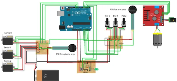
Electronics
The entire system is run by an Arduino Uno.[Arduino, 2016] This is a micro con-troller that is controlled by a given code. The system uses three smaller PCBs, see
3.3. ELECTRONICS
Figure 3.13. The purpose for this was to try and make the connections intuitive, where one PCB connects all the parts for the robotic arm and another for the arm unit. GND and 5V from each PCB are then connected to a third PCB that contains a button and a LED. This card has two functions. It connects all the 5V and GND, which then goes to the Arduino Uno. The button and LED will give the user the option to toggle the feedback system ON and OFF. When the LED is turned ON, the feedback system is ON. The button requires a pull-down resistor, in this case, 10KΩ is used. For the LED a 330Ω resistor is used.
Analog potentiometers are used for reading the position of the users arm. Through the software, the angle is mapped and fed to the servo motors via the Arduino Uno. The servos are powered by an external source to provide enough power. According to the datasheet for the servos, see Appendix A, maximum voltage was used, around 9V.
To implement the PID control, two force sensitive sensors are used. To work, they need a pull-down resistor. A 10KΩ resistor was used for each sensor. The reference value is received from the sensor on the robotic arm. The output value is received from the sensor on the hand unit. The PID controller regulates the PWM signal to the DC motor which corresponds to a force at the output sensor. The DC motor is connected via a H-bridge to the Arduino Uno. The DC motor needs a sep-arate voltage source. According to the datasheet for the DC motor, see Appendix A, the DC motor needs to be connected to 15V. For schematics of the system, see appendix A.
CHAPTER 3. DEMONSTRATOR
3.4
Software
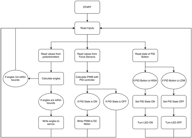
The Arduino Uno reads the values from the potentiometers. These values are mapped so the angle of the servo corresponds to the same angle as the poten-tiometer. This means that the servos will follow the same angle movement as the input from the potentiometers, see Figure 3.14. The values from the two FSRs are measured by the Arduino Uno. The value from the robotic arm is seen as the setpoint signal while the value from the arm unit is the output. Using the PID library,[Beauregard, 2016] it calculates the required signal to the DC motor via the H-bridge. The state of the button controls whether or not the PID State is ON which turns the haptic feedback on and off. The LED is also turned on or off depending on the PID state.
Figure 3.14. Program flowchart
3.4.1 PID
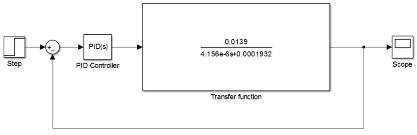
When calculating the step response for the feedback system, MATLAB Simulink is used. When inserting values for the DC motor given by the datasheet, see Appendix A, into Equation 2.1, we get the closed loop system as shown in Figure 3.15. By inserting different values for the parameters P,I and D, the different step response
3.5. MEASURING STEP RESPONSE
for each calculated system can be plotted. By inspecting these plots, it’s possible to see if the calculated values fulfills the requirements given in chapter 3.1 Problem formulation.
Figure 3.15. Closed loop for the feedback system.
3.5
Measuring step response
To evaluate the response of the feedback system, a simple measuring method was implemented. The main idea was to apply a force to the robotic claw and measure how the feedback system responds to the given force. A hand was placed in the arm unit and force was applied to the robotic claw. The feedback system would then make the FSR on the arm unit go from zero to the setpoint given by the force applied to the robotic arm. A problem with this method was that the arm unit would start twitching. This was because of the user could not keep the hand steady. A solution to this problem was to start the measuring from a small force instead of starting from no force. By doing this, the twitches were reduced a lot. The changed test method was therefore:
• Apply small force to the robotic claw.
• Let this value be the start point. For the step. function, set this value as the zero point.
• Rapidly increase the force and try to keep the force as constant as possible. • Measure the values of the FSR on the arm unit.
The code for the Arduino Uno was modified to a code for the measuring, see Appendix C for code and Figure 3.16 for flowchart diagram. This code began the measuring when the FSR on the robotic claw was given a force signal larger than 350. When measuring, values from the FSR of the arm unit were saved and then
CHAPTER 3. DEMONSTRATOR The printed values were then imported into a MATLAB script for further cal-culations, see Appendix D. This script scaled the values so the start values were set to zero and the reference were set to one. Plotting of the step response for each test was made, but also a plot with the averaged step response.
3.6. APPLICATION TESTING
3.6
Application testing
A small amount of randomly picked people tried the robotic arm. They had some time to feel different sized objects before the real testing began. The testing was done in two steps. The first was to feel two different objects while having their eyes shut. The test subject would then try to guess what object was the largest of the two. Different objects were used with the main focus to have two objects with large difference in size and two objects with a small difference in size. One of the tests was with the same object twice to see if they noticed it. This test was made multiple times, where two of the times, the difference in size was big, two times small and one time without difference.
Next test was to move an object once with the feedback turned ON and once with the feedback turned OFF. This was done with their eyes open. After the test the people had to answer the following questions:
1. Did the feedback system make the task easier? 2. Did the feedback system improve the experience?
The meaning of the second question is to see if the user feels like there is a better experience when being able to somewhat feel what the robotic arm is feeling.
Some weeks after the application testing was done, then idea of being able to feel objects with different softness was brought up. This test was done by grabbing a hard object and then a soft foam ball to see if a difference in feel could be noted.
3.7
Results
The robotic arm and the arm unit were placed on a wooden piece. This made the whole test station more compact and easy to move, see Figure 3.17.
CHAPTER 3. DEMONSTRATOR 3.7.1 PID
The theoretically calculated step response was made in MATLAB Simulink. Using pole placement calculations, different values for the parameters P, I and D were received. The overall best step response was found for a pole at s = −90, see Figure 3.18. This system does not use the D part, but fulfills the given requirements, see chapter 3.1 Problem formulation. The system has a very small overshoot with short settling time and almost no oscillations. Comparing this step response to the ones calculated with the pole placed at other positions did not give as good results, see Appendix E. The controllers using a D part did not improve the step response As mentioned, this did not give as good result as for the PI controller with the pole at s = -90. The best result for a PID was for the one given in Figure 3.19.
Figure 3.18. Step response function with Simulink for the pole s = -90. The values
3.7. RESULTS
Figure 3.19. Step response function with Simulink for the pole s = -0.001). The
values are: P = 1.4387, I = 0.0072, D = 71.9424. This system is very fast and has no overshoot. The problem with this system is that it has a constant error.
When measuring the step response for the real system, we got the results seen in Figure 3.20. The system is much slower than the theoretically calculated system.
Figure 3.20. Step response from measuring the real system. The measuring was
done ten times. Each blue plot corresponds to one measurement. The red plot corresponds to a step function.
CHAPTER 3. DEMONSTRATOR in Figure 3.21. This step response reduces the errors from the measuring itself.
Figure 3.21. Step response function from measuring the feedback system. This is
the mean value of all measured values. The red plot corresponds to a step function.
3.7.2 Application testing
The results from having a small amount of people do some application testing is given in Table 3.1. Every test subject could feel the difference of object size when the two objects differs a lot in size.
Big and small refers to the difference between the size of the grabbed objects. Big means that the two objects being grabbed has a big difference in size. Small means the opposite. No refers to having the subject grabbing the same object twice. The number "1" means that the answer is yes and "0" means no. For columns "Big","Small" and "No", "1" means that the test subject felt the difference and cor-rectly guessed what object was the largest.
Subject Big Small Small No Big
Does this make the task easier?
Does this improve the experience?
Questions Result Percentage Person 1 1 1 1 1 1 0 1 Big 5 100 Person 2 1 1 1 0 1 0 1 Small 4 80
Person 3 1 0 0 1 1 0 1 No 3 60 Person 4 1 1 1 0 1 0 1 Task easier? 1 20 Person 5 1 1 1 1 1 1 1 experience? 5 100
Chapter 4
Discussion and conclusions
4.1
Discussion
The servos did not seem to be able to create the torque given by the manufacturer. While it should be able to lift a weight of 0.5kg without any problem, it could hardly lift itself without added weight. This made us shorten the arm as much as possible (approximately 0.2m). This would require a torque around 0.14Nm. The robotic arm is still very weak and can hardly lift 0.1kg. Because of the design of the robotic arm mostly being created in CAD and 3D printed, buying a larger servo would require us to re-design most of the CAD models and 3D print them all again. This would be very time consuming. Because of the research question not being so dependent of the lifting part, we decided to leave the model as it was and focus on the feedback system itself.
The best step response was for a PI controller with poles at s = -90. With a very fast settling time, almost no overshoot, and very small oscillations, this system fulfilled our requirements from chapter 3.1. However with PID controller we get an error that is too large and also oscillations. This is probably due to the I part being too small. But with pole placement the parameters of the PID controller can’t be individually tuned which means that the inclusion of a D part causes the I part to shrink.
The response function of the real system differed a lot from the theoretical cal-culation that was made. As can be seen in Figure 3.21, the plot corresponds to a step response, but is much slower than the theoretical as can be seen in Figure 3.18. There are many reasons to why this is the case. When calculating the transfer func-tion, friction and inertia of the construction were neglected. The transfer function only takes the DC motor into account. The test method for calculating the real system’s step response is also a great factor of why the result differs so much from the theoretical calculations. The measuring was done mostly by "feel" and each test could differ a lot. The start and end value of the FSR of the robotic hand differed for each test. This would affect the amount of the error, thus the time would differ.
CHAPTER 4. DISCUSSION AND CONCLUSIONS it was very difficult to be able to have a constant reaction to the torque from the motor. Also, to get the reference value, the FSR value on the robotic arm was printed. This value was equal to the value of the FSR at the end of the test. This means that the value could have differed a lot during the test. By doing several tests and calculating the mean value, we were able to reduce the error of the measuring technique. For more accurate results, a test rig should have been built, to minimize the factors which are affecting the result. In hindsight, it would have been much better if we had inserted a value to the FSR on the robotic arm, instead of applying the force ourselves. This would have removed the variance of the input FSR signal. We had a very small amount of people to test the feedback system and answer some questions about its functionality. The reason of not having more people to test the unit was because of time limitations, but also that other areas felt more relevant. Even though the test data may not be sufficient, some interesting results may be considered. Every test subject were able to feel size difference in objects differing a lot in size, but also when the difference were not so large. However, when having the subjects grab the same objects twice, 60% thought that there is a difference in size. One reason for this may be that when testing, we might not have been clear enough that we would test the same object twice. Another aspect of this result is the construction itself. The connection between the DC motor and FSR with PID may lead to that the user’s hand closes a bit different every time grabbing an object. The system does only react to the reaction force from the grabbed object and not its actual size. If the user keep closing her hand when the counter torque is produced, the torque will increase but the hand will still be able to close. To be able to have a correct feeling of the object’s size, the user has to close the hand slowly and may have to decrease the force. 20% percent of the test subjects experienced that the moving task were easier with the feedback control. Perhaps this is because of the small distance between the user and the robotic arm. If the robotic arm were controlled from a greater distance via a screen, the result might have been different. Although the subjects did not feel that the design is making the task easier, 100% believed that it improved the experience i.e, the connection between the robot and the user, since they got a better feeling for what the robotic arm were grabbing.
When testing to grab objects with different softness, the difference was minimal. This is probably due to how the FSR work. It only registers the applied force. When grabbing the soft foam ball, the user were able to close her hand a bit more because of the compression of the ball. This made the user to believe that the object being grabbed is smaller.
The softness test was very simply executed. If more sensors were implemented on the users hand and the robotic arm, the chance of feeling different softness would have increased.
4.2. CONCLUSIONS
4.2
Conclusions
A PI controller with the values P = 0.0536 and I = 2.4215 seems to be best for our feedback system.
The PID system differed quite a lot from the simulated model. The reasons are many. We neglected some friction forces, but also the measuring of the feedback system had some drawbacks.
For improving the control of robotic arms, using a control method based on your own arm movement is a concept that seems to be beneficial. Controlling a robotic claw with haptic feedback where the user can get some kind of feeling for the size of the object being lifted, improves the application of controlling a robotic arm. A simple feedback system for robotic arms could be very beneficial for the future of robotics in the industry. When the user and robot are in different places this could improve the application a lot. Using potentiometer for registering the user’s arm movement and mapping this to servos seem to be simple but yet a good way of controlling a robotic arm. If the robotic arm would be of greater size, servos might not be the best solution.
Chapter 5
Recommendations and future work
5.1
Recommendations
We would recommend getting bigger and preferably higher quality servos for the robotic arm.
The measuring for the feedback system in reality should be done better. The input value for the FSR on the robotic arm should be inserted as an input value in the code rather than by pressing the FSR.
5.2
Future work
Since this unit was made for testing the feedback system, it fulfilled its requirements. For future testings, the robotic arm should be designed to fit stronger servos. This enables testing of moving larger objects.
The gripping claw could be improved by making it more similar to a hand with five fingers. This means having one FSR for each finger on the robotic arm and the arm unit. This would enable the testing of objects with different shapes.
One thing that we wanted to do was to be able to record the movement of the robotic arm. This would enable the user to do a task once, and the robotic arm would then be able to do the same task on its own. This leads to the fact that a user with no robotic experience could easily set up the robotic arm’s movement. This would be very beneficial to the industry, where you would not need an engineer to make a change in the settings for the robotic arm to do the new task.
The feedback system could be improved so that the user could be able to feel the softness of the object being grabbed. This may be done by building a gripping claw that has five fingers and five sensors. The arm unit would have one sensor and one dc motor for each finger. This might improve the aspect of being able to feel different softness.
Bibliography
[Arduino, 2016] Arduino. Arduino - arduinoboarduno [online]. (2016) [cited 2016-05-07]. Available from: https://www.arduino.cc/en/Main/ArduinoBoardUno. [Beauregard, 2016] Beauregard, B. Arduino pid library [online]. (2016) [cited
2016-04-20]. Available from: http://playground.arduino.cc/Code/PIDLibrary. [bluebean, 2012] bluebean. Motion controlled robotic arm [online]. (2012) [cited
2016-05-24]. Available from: http://www.instructables.com/id/Intro-53/. [Epilog Laser, 2016] Epilog Laser. Epilog fusion m2 laser series [online]. (2016)
[cited 2016-05-07]. Available from: https://www.epiloglaser.com/products/ fusion-laser-series.htm.
[Glad and Ljung, 2006] Glad, T. and Ljung, L. (2006). Reglerteknik - Grundläg-gande teori. Studenlitteratur, 4th edition.
[HAGERTY, 2015] HAGERTY, J. R. (2015). Meet the new
generation of robots for manufacturing. Wall street
jour-nal. Available from: http://www.wsj.com/articles/
meet-the-new-generation-of-robots-for-manufacturing-1433300884 [cited 2016-03-06].
[IndustryWeek, 2012] IndustryWeek, Josh, C. The future of robotics in man-ufacturing: Moving to the other side of the factory [online]. (2012) [cited 2016-03-06]. Available from: http://www.industryweek.com/robotics/ future-robotics-manufacturing-moving-other-side-factory.
[Keystone Electronics Corp, 2013] Keystone Electronics Corp. How robots have changed manufacturing [online]. (2013) [cited 2016-03-06]. Available from: http: //www.keyelco.com/blog-details.cfm?blog_id=40.
[Margolis, 2009] Margolis, M. Arduino servo library [online]. (2009) [cited 2016-03-07]. Available from: https://www.arduino.cc/en/Reference/Servo.
[MathWorks Nordic, 2015a] MathWorks Nordic. Matlab - the language of tech-nical computing [online]. (2015) [cited 2016-05-07]. Available from: http:
BIBLIOGRAPHY [MathWorks Nordic, 2015b] MathWorks Nordic. Simulink - simulation and model-based design [online]. (2015) [cited 2016-05-07]. Available from: http://se. mathworks.com/products/simulink/.
[Okamura, 2009] Okamura, A. M. (2009). Haptic feedback in robot-assisted min-imally invasive surgery. US National Library of Medicine National Institutes of Health. Available from: http://www.ncbi.nlm.nih.gov/pmc/articles/ PMC2701448/[cited 2016-03-06].
[PATTNAIK, 2013] PATTNAIK, A. Robotic arm control through human arm movement using accelerometers [online]. (2013) [cited 2016-05-24]. Available from: http://ethesis.nitrkl.ac.in/5283/1/109EI0297.pdf.
[Siemens PLM Software, 2016] Siemens PLM Software. Solid edge. [online]. (2016) [cited 2016-05-07]. Available from: https://www.plm.automation.siemens. com/en_us/products/solid-edge/.
[Ultimaker BV, 2016] Ultimaker BV. Ultimaker 2 [online]. (2016) [cited 2016-05-07]. Available from: https://ultimaker.com/en/products/ultimaker-2-go. [Univeristy of Michigan, 2016] Univeristy of Michigan. DC Motor Speed:
System Modeling [online]. (2016) [cited 2016-03-20]. Available from: http://ctms.engin.umich.edu/CTMS/index.php?example=MotorSpeed& section=SystemModeling.
Appendix A
APPENDIX A. DATASHEETS
APPENDIX A. DATASHEETS
Appendix B
APPENDIX B. SCHEMATICS
Appendix C
APPENDIX C. ARDUINO CODE
Arduino code with servo control and haptic feedback
1 /∗ D e s c r i p t i o n
2 This i s the main code f o r the whole system .
3 I t converts the s i g n a l from potentiometers to s e r v o s . 4 A PID c o n t r o l i s implemented f o r c o n t r o l l i n g
5 the FSR s i g n a l s . This uses a PID l i b r a r y . 6 ∗/
7
8 #i n c l u d e <PID_v1 . h> // Import PID l i b r a r y 9
10 #i n c l u d e <Servo . h> // import servo package 11 Servo myservo0 ; // Servo f o r r o b o t i c arm ( base ) 12 Servo myservo1 ; // Servo f o r r o b o t i c arm (arm) 13 Servo myservo2 ; // Servo f o r r o b o t i c arm ( claw ) 14
15 i n t potPin0 = 0 ; // Potentiometer 0 , arm unit ( base ) 16 i n t potPin1 = 1 ; // Potentiometer 1 , arm unit (arm) 17 i n t potPin2 = 2 ; // Potentiometer 2 , arm unit ( claw ) 18
19 // Connections to H−bridge 20 i n t IN1 = 1 ; //Motor IN1 21 i n t IN2 = 2 ; //Motor IN2 22 i n t ENA = 3 ; //Motor ENA 23 double PWM; 24 25 i n t val0 ; // I n i t i a t e v a r i a b l e 26 i n t val1 ; // I n i t i a t e v a r i a b l e 27 i n t val2 ; // I n i t i a t e v a r i a b l e 28 29 // V a r i a b l e s f o r PID
30 double Actual , Error , I n t e g r a l , P, I , D, ScaleFactor , Drive ,
Direction , Last ;
31
32 i n t fsrPinHand = 3 ; //FSR and 10K pulldown connected to a3 33 i n t fsrPinRobot = 4 ; //FSR and 10K pulldown connected to a4 34
35 //The analog reading from the FSR r e s i s t o r d i v i d e r
36 double fsrReadingRobot , fsrReadingHand , fsrReadingRobotMap ,
fsrReadingHandMap ;
37
38 double Setpoint , Input , Output ; 39
41 i n t inPin = 5 ; // Input pin used f o r a on/ o f f switch 42 i n t outPin = 4 ; //Output pin used f o r LED
43 i n t PIDstate = HIGH; // Curent s t a t e . Turning feedback on/ o f f 44 i n t Buttonreading ; //The current reading from input pin 45 i n t previous = LOW; //The previous reading from input pin 46 long time = 0 ; //The l a s t time the output pin was toggled 47 long debounce = 200; //Debounce time , i n c r e a s e i f output
f l i c k e r s
48 49
50 /∗ S e t t i n g up PID using the l i b r a r y
51 ∗ Input : The v a r i a b l e to be c o n t r o l l e d ( double ) 52 ∗Output : The v a r i a b l e to adjust by the pid ( double )
53 ∗ Setpoint : The value we want to Input to maintain ( double ) 54 ∗Kp, Ki , Kd: Tuning Parameters ( double >=0)
55 ∗ D i r e c t i o n : DIRECT or REVERSE. determines which d i r e c t i o n 56 ∗ the output w i l l move when faced with a given e r r o r . 57 ∗/
58
59 //The c a l c u l a t e d constants f o r PID
60 double Kp = 0.0536 , Ki = 2.4215 , Kd = 0 ;
61 PID myPID(&fsrReadingHand , &Drive , &fsrReadingRobot , Kp, Ki ,
Kd, DIRECT) ;
62 63
64 void setup ( ) { 65
66 myPID . SetMode (AUTOMATIC) ; // S e t t i n g up the PID l i b r a r y 67
68
69 pinMode ( inPin , INPUT) ; //The switch i s an input s i g n a l 70 pinMode ( outPin , OUTPUT) ; //The LED i s an output s i g n a l 71
72 S e r i a l . begin (9600) ; // S e r i a l between Arduino and computer 73
74 myservo0 . attach ( 9) ; // D i g i t a l pin 9 f o r servo 0 75 myservo1 . attach (10) ; // D i g i t a l pin 10 f o r servo 1 76 myservo2 . attach (11) ; // D i g i t a l pin 11 f o r servo 2 77
78 pinMode ( IN1 , OUTPUT) ; // D i g i t a l pin = output 79 pinMode ( IN2 , OUTPUT) ; // D i g i t a l pin = output 80 d i g i t a l W r i t e ( IN1 , LOW) ; // Rotate forward
APPENDIX C. ARDUINO CODE
83 }
84 void loop ( ) 85 {
86 //On/ Off part
87 Buttonreading = d i g i t a l R e a d ( inPin ) ;
88 /∗ i f the input j u s t went from LOW and HIGH and we ’ ve waited
long enough
89 ∗ to i g n o r e any n o i s e on the c i r c u i t , t o g g l e the output pin
and remember
90 ∗ the time 91 ∗/
92 i f ( Buttonreading == HIGH && previous == LOW && m i l l i s ( ) −
time > debounce ) { 93 i f ( PIDstate == HIGH) 94 PIDstate = LOW; 95 e l s e 96 PIDstate = HIGH; 97 time = m i l l i s ( ) ; 98 } 99 100 101 d i g i t a l W r i t e ( outPin , PIDstate ) ; 102 103 previous = Buttonreading ; 104 105 //SERVO PART
106 val0 = analogRead ( potPin0 ) ; //Read analog 0 107 val1 = analogRead ( potPin1 ) ; //Read analog 1 108 val2 = analogRead ( potPin2 ) ; //Read analog 2 109
110 //Change range o f potentiometers 111 val0 = map( val0 , 0 , 614 , 0 , 179) ; 112 val1 = map( val1 , 0 , 614 , 0 , 179) ; 113 val2 = map( val2 , 791 , 1023 , 50 , 140) ; 114
115 // This part c r e a t e s some l i m i t a t i o n s f o r the movement . 116 // Servo 0 base
117 i f ( val0 < 179) 118 {
119 myservo0 . write ( val0 ) ; // Potentiometer to servo 120 }
121
122 // servo 1 arm
124 { 125
126 myservo1 . write ( val1 ) ; // Potentiometer to servo 127 }
128
129 // servo 2 claw 130 i f ( val2 < 179) 131 {
132 myservo2 . write ( val2 ) ; // Potentiometer to servo 133 }
134
135 //PID PART
136 fsrReadingRobot = analogRead ( fsrPinRobot ) ; // Analog s i g n a l
from robot FSR
137 fsrReadingRobotMap = map( fsrReadingRobot , 0 , 995 , 0 , 255) ;
//Change range
138
139 fsrReadingHand = analogRead ( fsrPinHand ) ; // Analog s i g n a l
from hand FSR
140 fsrReadingHandMap = map( fsrReadingHand , 0 , 995 , 0 , 255) ;
//Change range
141
142 myPID . Compute ( ) ; // Calculate PID 143 144 i f ( fsrReadingRobot == 0) { 145 Drive = 0 ; 146 } 147 // /// PID On or OFF////// 148 i f ( PIDstate == HIGH) {
149 analogWrite (ENA, Drive ) ; //Send PWM command to motor
board
150 S e r i a l . p r i n t ("PID IS ON ! ! ! ") ; 151 }
152 e l s e {
153 Drive = 0 ;
154 analogWrite (ENA, Drive ) ; //Send PWM command to motor
board
155 S e r i a l . p r i n t ("PID IS OFF ! ! ! ") ; 156 }
157
158 // This part p r i n t s important values to the s e r i a l monitor 159 S e r i a l . p r i n t (" Analog reading Robot = ") ;
APPENDIX C. ARDUINO CODE
162 S e r i a l . p r i n t (" Analog reading Hand = ") ; 163 S e r i a l . p r i n t ( fsrReadingHand ) ; 164 165 166 S e r i a l . p r i n t (" PWM = ") ; 167 S e r i a l . p r i n t ( Drive ) ; 168 169 S e r i a l . p r i n t (" Pot0 = ") ; 170 S e r i a l . p r i n t ( val0 ) ; 171 172 S e r i a l . p r i n t (" Pot1 = ") ; 173 S e r i a l . p r i n t ( val1 ) ; 174 S e r i a l . p r i n t (" Pot2 = ") ; 175 S e r i a l . p r i n t l n ( val2 ) ; 176 177 }
Arduino code for step response measurement
1 /∗ D e s c r i p t i o n
2 ∗ This code c a l c u l a t e s the step response 3 ∗ f o r the system . When the FSR on the r o b o t i c 4 ∗ hand i s pressed so that the value o f the FSR 5 ∗ g e t s over 350 , the measuring s t a r t s . Afterwards 6 ∗ the program p r i n t s the FSR values from the 7 ∗ arm unit . This data can be copied and pasted 8 ∗ i n t o MATLAB f o r f u r t h e r c a l c u l a t i o n s
9 ∗/ 10
11 #i n c l u d e <PID_v1 . h> // Import PID l i b r a r y 12
13 //Timer f o r the measuring 14 i n t time0 = m i l l i s ( ) ; 15 i n t time1 = 0 ;
16 i n t i n t e r v a l 2 = 5 0; 17 i n t i n t e r v a l = 5 0;
18 i n t array [ 4 0 ] ; //Empty l i s t f o r measured FSR 19
20 i n t le d = 1 3 ; //LED pin 21
22 // Connections to H−bridge 23 i n t IN1=1; //Motor IN1 24 i n t IN2=2; //Motor IN2 25 i n t ENA=3; //Motor ENA 26 double Drive ;
27 double PWM; 28
29 i n t fsrPinRobot = 4 ; //FSR and 10K pulldown connected to a3 30 i n t fsrPinHand = 3 ; //FSR and 10K pulldown connected to a4 31
32 double fsrReadingRobot , fsrReadingHand , fsrReadingRobotMap ,
fsrReadingHandMap ; //The analog reading from the FSR
r e s i s t o r d i v i d e r
33
34 double Setpoint , Input , Output ; 35
36 // S p e c i f y the l i n k s and i n i t i a l tuning parameters 37 double Kp = 0.0536 , Ki = 2.4215 , Kd = 0 ;
38
APPENDIX C. ARDUINO CODE
41
42 i n t PIDstate = HIGH; // Current s t a t e o f the output pin 43 i n t Buttonreading ; // Current reading from the input pin 44 i n t previous = LOW; // Previous reading from the input pin 45
46 // the f o l l o w v a r i a b l e s are long ’ s because the time ,
measured in miliseconds ,
47 // w i l l q u i c k l y become a b i g g e r number than can be s t o r e d in
an i n t .
48 long time = 0 ; //The l a s t time the output pin was toggled 49 long debounce = 200; //The debounce time , i n c r e a s e i f the
output f l i c k e r s 50 i n t pla ce = 0 ; 51 i n t count = 0 ; 52 char s t a r t = ’ 0 ’; 53 i n t STARTTID; 54 55
56 /∗ S e t t i n g up PID using the l i b r a r y
57 ∗ Input : The v a r i a b l e to be c o n t r o l l e d ( double ) 58 ∗Output : The v a r i a b l e to adjust by the pid ( double )
59 ∗ Setpoint : The value we want to Input to maintain ( double ) 60 ∗Kp, Ki , Kd: Tuning Parameters ( double >=0)
61 ∗ D i r e c t i o n : DIRECT or REVERSE. determines which d i r e c t i o n 62 ∗ the output w i l l move when faced with a given e r r o r . 63 ∗/
64 PID myPID(&fsrReadingHand , &Drive , &fsrReadingRobot ,Kp, Ki ,Kd
, DIRECT) ;
65 void setup ( ) { 66
67 myPID . SetMode (AUTOMATIC) ; // S e t t i n g up the PID l i b r a r y 68
69 pinMode ( inPin , INPUT) ; 70 pinMode ( outPin , OUTPUT) ;
71 S e r i a l . begin (9600) ; // Set up the s e r i a l 72
73 pinMode ( IN1 ,OUTPUT) ; // D i g i t a l pin = output 74 pinMode ( IN2 ,OUTPUT) ; // D i g i t a l pin = output 75 d i g i t a l W r i t e ( IN1 ,LOW) ; // Rotate forward 76 d i g i t a l W r i t e ( IN2 ,HIGH) ;
77 S e r i a l . p r i n t l n (" Begin t e s t i n g ") ; 78
79 }
81 { 82
83 d i g i t a l W r i t e ( outPin , PIDstate ) ; 84
85 //PID PART
86 fsrReadingRobot = analogRead ( fsrPinRobot ) ;
87 fsrReadingRobotMap = map( fsrReadingRobot , 0 , 995 , 0 , 255) ;
//Change range
88
89 fsrReadingHand = analogRead ( fsrPinHand ) ;
90 fsrReadingHandMap = map( fsrReadingHand , 0 , 995 , 0 , 255) ; //
Change range
91
92 myPID . Compute ( ) ; // Calculate PID 93 94 95 // /// PID On or OFF////// 96 i f ( fsrReadingRobot == 0) { 97 Drive = 0 ; 98 } 99 100
101 analogWrite (ENA, Drive ) ; // send PWM command to motor board 102 S e r i a l . p r i n t l n ( Drive ) ;
103 S e r i a l . p r i n t ( fsrReadingRobot ) ; 104
105 // Startmeasuring i f the FSR reading i s g r e a t e r than 350 106 i f( fsrReadingRobot >=350 && p lace == 0) {
107 STARTTID = m i l l i s ( ) ;
108 array [ place ] = fsrReadingHand ;
109 place++;
110 111 }
112 // Startmeasuring i f the FSR reading i s g r e a t e r than 350 113 i f ( fsrReadingRobot >=350){
114 i f( m i l l i s ( )−STARTTID >= i n t e r v a l 2 ) { 115 i n t e r v a l 2 = i n t e r v a l 2 + i n t e r v a l ; 116 array [ place ] = fsrReadingHand ;
117 place++;
118 }
119 // Print the values a f t e r measuring i s done , 2 seconds 120 i f( m i l l i s ( )−STARTTID >= 2000) {
APPENDIX C. ARDUINO CODE 123 S e r i a l . p r i n t (" , ") ; 124 } 125 S e r i a l . p r i n t l n (" ") ; 126 S e r i a l . p r i n t l n ("EFTER ARRAY") ; 127 S e r i a l . p r i n t l n ( fsrReadingRobot ) ; 128 delay (100000) ; 129 } 130 } 131 132 count++; 133 }
Appendix D
APPENDIX D. MATLAB CODE
Matlab program for real step response
1 %This code c a l c u l a t e s the step response f o r the r e a l system .
The system i s
2 %measured 10 times . The mean value i s then c a l c u l a t e d . The
time o f
3 %measurement i s 2 seconds . The v a r i a b l e t a r g e t i s the
systems t a r g e t value .
4 %The measurement values are taken from a t e s t using a
Arduino UNO.
5 c l e a r a l l , clc , c l o s e a l l 6
7 numberOfMeasurements = 10 ;
8 %t a r g e t x = t a r g e t value f o r the system . 9 %measurex = FSR analog read value . 10 t a r g e t {1} = 574; 11 measure {1} = [ 3 4 9 , 3 5 7 , 3 4 4 , 3 5 8 , 3 6 8 , 3 7 6 , 4 0 1 , 4 3 6 , 4 9 2 , 5 0 0 , . . . 12 5 1 7 , 5 3 3 , 5 4 2 , 5 5 6 , 5 5 7 , 5 6 4 , 5 6 7 , 5 6 8 , 5 6 9 , 5 7 2 , . . . 13 5 6 9 , 5 6 8 , 5 6 4 , 5 6 9 , 5 7 1 , 5 7 1 , 5 7 2 , 5 7 2 , 5 6 8 , 5 6 7 , . . . 14 570 ,575 ,576 ,575 ,575 ,578 ,577 ,574 ,576 ,575]; 15 16 t a r g e t {2} = 553; 17 measure {2} = [ 2 9 8 , 3 2 5 , 3 3 2 , 3 4 1 , 3 6 2 , 4 3 0 , 4 4 4 , 4 6 0 , 4 8 1 , 5 0 7 , . . . 18 5 2 1 , 5 2 8 , 5 4 2 , 5 4 3 , 5 4 7 , 5 4 6 , 5 5 3 , 5 5 3 , 5 5 5 , 5 5 8 , . . . 19 5 6 3 , 5 6 5 , 5 6 8 , 5 7 4 , 5 7 9 , 5 8 0 , 5 7 4 , 5 7 4 , 5 7 3 , 5 7 4 , . . . 20 573 ,576 ,577 ,577 ,577 ,576 ,576 ,573 ,574 ,566]; 21 22 t a r g e t {3} = 659; 23 measure {3} = [ 3 5 0 , 3 5 9 , 3 6 8 , 4 0 2 , 4 1 7 , 4 4 4 , 4 7 2 , 4 9 9 , 5 3 1 , 5 4 7 , . . . 24 5 5 6 , 5 6 6 , 5 7 5 , 5 8 6 , 5 9 4 , 6 0 0 , 6 1 6 , 6 2 4 , 6 2 3 , 6 2 4 , . . . 25 6 2 7 , 6 2 9 , 6 3 2 , 6 3 2 , 6 3 7 , 6 4 4 , 6 3 9 , 6 4 1 , 6 4 4 , 6 4 7 , . . . 26 655 ,660 ,665 ,665 ,666 ,670 ,671 ,667 ,662 ,662]; 27 28 t a r g e t {4} = 593; 29 measure {4} = [ 2 8 1 , 2 8 0 , 2 7 1 , 2 9 4 , 3 4 5 , 4 2 7 , 4 6 7 , 4 8 8 , 5 0 8 , 5 1 9 , . . . 30 5 3 4 , 5 4 2 , 5 5 0 , 5 5 7 , 5 6 4 , 5 6 7 , 5 7 3 , 5 8 5 , 5 9 5 , 5 9 6 , . . . 31 6 0 0 , 6 0 1 , 6 0 3 , 5 9 9 , 6 0 9 , 6 1 1 , 6 1 1 , 6 0 9 , 6 1 3 , 6 1 2 , . . . 32 615 ,614 ,609 ,616 ,622 ,623 ,620 ,623 ,630 ,634]; 33 34 t a r g e t {5} = 563; 35 measure {5} = [ 2 9 1 , 2 9 3 , 3 0 0 , 3 0 6 , 3 2 9 , 3 4 6 , 3 7 5 , 4 4 0 , 4 5 5 , 4 8 5 , . . . 36 5 1 5 , 5 2 7 , 5 4 6 , 5 4 4 , 5 5 3 , 5 5 6 , 5 6 0 , 5 6 9 , 5 6 4 , 5 6 7 , . . . 37 5 6 4 , 5 7 0 , 5 6 2 , 5 6 8 , 5 6 6 , 5 6 7 , 5 6 6 , 5 6 5 , 5 5 8 , 5 4 7 , . . . 38 536 ,527 ,523 ,526 ,524 ,528 ,529 ,537 ,547 ,553];
39 40 t a r g e t {6} = 589; 41 measure {6} = [ 2 5 4 , 2 6 5 , 2 8 8 , 3 6 4 , 4 3 5 , 4 6 2 , 4 8 3 , 4 9 4 , 5 2 3 , 5 2 9 , . . . 42 5 3 3 , 5 4 0 , 5 4 5 , 5 5 5 , 5 6 3 , 5 6 8 , 5 6 8 , 5 7 2 , 5 7 8 , 5 7 7 , . . . 43 5 7 6 , 5 8 0 , 5 8 6 , 5 9 6 , 5 9 3 , 5 9 9 , 6 0 4 , 5 9 8 , 5 9 6 , 5 9 5 , . . . 44 603 ,591 ,582 ,577 ,575 ,578 ,579 ,589 ,590 ,584]; 45 46 t a r g e t {7} = 573; 47 measure {7} = [ 2 4 8 , 2 5 5 , 3 2 9 , 3 5 5 , 3 9 8 , 4 3 2 , 4 9 5 , 5 2 1 , 5 6 1 , 5 7 3 , . . . 48 5 6 6 , 5 6 0 , 5 5 8 , 5 5 7 , 5 5 0 , 5 4 7 , 5 4 6 , 5 5 4 , 5 5 8 , 5 6 0 , . . . 49 5 6 7 , 5 6 6 , 5 6 6 , 5 6 2 , 5 5 9 , 5 6 1 , 5 5 8 , 5 5 9 , 5 5 1 , 5 4 9 , . . . 50 550 ,552 ,552 ,553 ,553 ,559 ,561 ,562 ,563 ,568]; 51 52 t a r g e t {8} = 513; 53 measure {8} = [ 2 3 8 , 2 6 0 , 3 2 6 , 3 5 1 , 3 8 3 , 4 3 1 , 4 5 7 , 5 0 3 , 5 1 2 , 5 0 3 , . . . 54 5 1 0 , 5 1 4 , 5 0 9 , 5 1 3 , 5 1 3 , 5 0 8 , 5 1 2 , 5 1 4 , 5 1 2 , 5 1 1 , . . . 55 5 0 6 , 5 0 4 , 5 0 0 , 5 0 2 , 5 0 4 , 4 9 6 , 5 0 0 , 5 0 2 , 5 0 2 , 5 0 0 , . . . 56 510 ,514 ,514 ,523 ,524 ,532 ,538 ,538 ,538 ,532]; 57 58 t a r g e t {9} = 579; 59 measure {9} = [ 2 8 1 , 3 0 5 , 3 7 3 , 3 9 2 , 4 6 0 , 4 8 0 , 5 1 2 , 5 2 9 , 5 4 5 , 5 6 7 , . . . 60 5 7 8 , 5 9 1 , 5 9 8 , 6 0 0 , 5 9 9 , 6 0 5 , 6 0 6 , 6 1 0 , 6 1 8 , 6 1 9 , . . . 61 6 1 6 , 6 0 9 , 6 1 2 , 6 1 5 , 6 2 3 , 6 2 6 , 6 2 8 , 6 2 8 , 6 2 7 , 6 2 6 , . . . 62 626 ,621 ,617 ,613 ,613 ,607 ,607 ,599 ,593 ,574]; 63 64 t a r g e t {10} = 558; 65 measure {10} = [ 2 4 2 , 2 5 5 , 2 8 7 , 3 1 1 , 3 7 4 , 4 0 0 , 4 2 1 , 4 4 2 , 4 6 4 , 4 8 9 , . . . 66 4 9 3 , 4 9 6 , 4 9 9 , 5 0 2 , 5 0 3 , 5 0 3 , 5 0 5 , 5 0 6 , 5 1 0 , 5 1 1 , . . . 67 5 1 3 , 5 1 7 , 5 2 1 , 5 2 6 , 5 2 5 , 5 2 2 , 5 2 5 , 5 2 5 , 5 2 9 , 5 2 6 , . . . 68 523 ,529 ,532 ,529 ,527 ,535 ,537 ,530 ,534 ,537]; 69
70 %Time goes from 1 to 3 seconds 71 i n t e r v a l = 0 . 0 5 ;
72 measureTime = 1:0.05:3 − i n t e r v a l ; 73 totalTime = 0 : i n t e r v a l :3 −0.05 74
75 %Creates a step response f u n c t i o n f o r r e f e r e n c e s i g n a l 76 r e f S i g n a l = [ 0 0 1 1 1 ]
77 x=[0 1 1 2 3 ]
78 p l o t(x , r e f S i g n a l , ’ r ’) 79 hold on
APPENDIX D. MATLAB CODE
83 targetVal = [ ] ; 84
85 %Start value f o r t o t a l value o f a l l measurements . 86 t o t a l V a l = 0
87 f o r i = 1 : numberOfMeasurements
88 %Create l i s t s with s t a r t values and tareg values . 89 s t a r t V a l ( i ) = measure{ i }(1) ;
90 targetVal ( i ) = t a r g e t { i } ; 91
92 %To make the measurements s t a r t from zero f o r our 93 %t r a n s f e r function , s u b t r a c t the s t a r t i n g value . 94 measurementFromZero{ i } = measure{ i }−s t a r t V a l ( i ) ; 95
96 %To make the measurement go to 1 ( step f u n c t i o n ) we
s c a l e the
97 %measurement .
98 scaledMeasurement { i } = measurementFromZero{ i } . / (
targetVal ( i )−s t a r t V a l ( i ) ) ;
99
100 %Creates a p l o t with a l l the measurements 101 f i g u r e(1 )
102 p l o t( measureTime , scaledMeasurement { i } , ’b ’) 103 t i t l e ( ’ Step response f u n c t i o n o f r e a l system ’) 104 x l a b e l(’ Time [ s ] ’) 105 y l a b e l(’ Step response ’) 106 a x i s( [ 0 3− i n t e r v a l 0 1 . 5 ] ) 107 hold on 108 g r i d on 109
110 %Calculate the t o t a l value o f a l l the s c a l e d
measurements . This w i l l be
111 %used f o r c a l c u l a t i o n o f the mean value f o r the measured
system .
112 t o t a l V a l = t o t a l V a l+scaledMeasurement { i } ; 113 end
114
115 %Calculate mean value .
116 meanVal = t o t a l V a l /numberOfMeasurements ; 117
118 %Creates a p l o t with the mean value . 119 f i g u r e(2 )
120 p l o t( measureTime , meanVal )
121 t i t l e (’ Step response f u n c t i o n f o r r e a l system (mean value ) ’) 122 x l a b e l( ’ Time [ s ] ’)
123 y l a b e l( ’ Step response ’) 124 a x i s( [ 0 3− i n t e r v a l 0 1 . 5 ] ) 125 g r i d on
126 hold on
127 %add the r e f e r e n c e s i g n a l in the p l o t 128 p l o t(x , r e f S i g n a l , ’ r ’)
APPENDIX D. MATLAB CODE
Matlab program for pole placement
1 %This program c a l c u l a t e s the appropriate constants f o r
d i f f e r e n t
2 %c o n t r o l l e r s 3
4 c l e a r a l l , clc , c l o s e a l l
5 %Values f o r the motor from datasheet (maxon motor 110123) 6 J = 4.27 + 0 . 4 ; %gcm^2 ( Rotor i n e r t i a )
7 J = J∗1e−3∗1e −4; %kgm^2
8 b = 0 ; %N∗m∗ s ( motor v i s c o u s f r i c t i o n constant ) 9 K = 1 3 . 9 ; %mNm/A ( Torque constant )
10 K = K∗1e −3; 11 R = 8 . 9 ;%Ohm ( e l e c t r i c r e s i s t a n c e ) 12 L = 0.585∗1 e −3; %e l e c t r i c inductance 13 L=0; 14 15 16 %T r a n s f e r f u n c t i o n f o r the motor 17 s = t f (’ s ’) ; 18 G_motor = K/ (( J∗ s+b) ∗(L∗ s+R)+K^2) 19
20 SystemPoles = pole (G_motor) ; %The p o l e s 21 %o f the motor t r a n s f e r f u n c t i o n
22
23 %Using pole placement to c a l c u l a t e 24 %P, I , and D parameters by p l a c i n g p o l e s
25 %f o r the denominator o f the c l o s e d loop system 26 27 %Using only PI c o n t r o l l e r 28 %Pole at s = −47 29 PoleEquation47 = ( s +47)^2 30 P47 = 94∗(4.156 e −6/0.0139) − 0.0001932 31 I47 = (2209 −1) ∗(4.156 e −6/0.0139) 32 %Pole at s = −70 33 PoleEquation70 = ( s +70) ^2; 34 P70 = 140∗(4.156 e −6/0.0139) − 0 . 0 0 0 1 9 3 2 ; 35 I70 = (4900 −1) ∗(4.156 e −6/0.0139) ; 36 %Pole at s = −100 37 PoleEquation100 = ( s +100) ^2; 38 P100 = 200∗(4.156 e −6/0.0139) − 0 . 0 0 0 1 9 3 2 ; 39 I100 = (10000 −1) ∗(4. 156 e −6/0.0139) ; 40 %Pole at s = −150 41 PoleEquation150 = ( s +150) ^2;
42 P150 = 300∗(4.156 e −6/0.0139) − 0 . 0 0 0 1 9 3 2 ; 43 I150 = (22500 −1) ∗(4.156 e −6/0.0139) ; 44 %Pole at s = −90 45 PoleEquation90 = ( s +90) ^2; 46 P90 = 180∗(4.156 e −6/0.0139) − 0 . 0 0 0 1 9 3 2 ; 47 I90 = (8100 −1) ∗(4.156 e −6/0.0139) ; 48
49 %Using the whole PID 50 %Pole at s = −47 51 P47_2 = 94/0.0139 − 0 . 0 0 0 1 9 3 2 ; 52 I47_2 = 2209/0.0139; 53 D47_2 = 1/0.0139 − 4.156 e −6; 54 %Pole at s = −0.1 55 PoleEquation01 = ( s +0.1) ^2; 56 P01_2 = 0 . 2 / 0 . 0 1 3 9 − 0 . 0 0 0 1 9 3 2 ; 57 I01_2 = 0 . 0 1 / 0 . 0 1 3 9 ; 58 D01_2 = 1/0.0139 − 4.156 e −6; 59 %Pole at s = −0.01 60 PoleEquation001 = ( s +0.01) ^2; 61 P001_2 = 0.02/0.0139 − 0 . 0 0 0 1 9 3 2 ; 62 I001_2 = 0 . 0 0 0 1 / 0 . 0 1 3 9 ; 63 D001_2 = 1/0.0139 − 4.156 e −6;
Appendix E
APPENDIX E. PLOTS
Plots of step response for different poles with PI
con-troller
Figure E.1. Step response function with Simulink for the pole s = -47. The values
Figure E.2. Step response function with Simulink for the pole s = -70). The values
are: P = 0.0417, I = 1.4648. This system has a shorter settling time than the system with the pole s =-47.
APPENDIX E. PLOTS
Figure E.3. Step response function with Simulink for the s = -100). The values are:
P = 0.0596, I = 2.9896. This system has a shorter settling time than the the systems
for pole s = -47 and s = -70. The problem with this system is that it produces a small overshoot.
Figure E.4. Step response function with Simulink for the pole s = -150). The values are: P = 0.0895, I = 6.7270. This is a very fast system, but has quite a large overshoot.