Low-Power Listening Goes Multi-Channel
Beshr Al Nahas
∗, Simon Duquennoy
∗, Venkatraman Iyer
†, Thiemo Voigt
∗† ∗SICS Swedish ICT AB, Sweden{beshr,simonduq,thiemo}@sics.se
†Uppsala University, Sweden
venkatraman.iyer@it.uu.se Abstract—Exploiting multiple radio channels for
communi-cation has been long known as a practical way to mitigate interference in wireless settings. In Wireless Sensor Networks, however, multi-channel solutions have not reached their full potential: the MAC layers included in TinyOS or the Contiki OS for example are mostly single-channel. The literature offers a number of interesting solutions, but experimental results were often too few to build confidence. We propose a practical extension of low-power listening, MiCMAC, that performs channel hopping, operates in a distributed way, and is independent of upper layers of the protocol stack. The above properties make it easy to deploy in a variety of scenarios, without any extra configura-tion/scheduling/channel selection hassle. We implement our solu-tion in Contiki and evaluate it in a 97-node testbed while running a complete, out-of-the-box low-power IPv6 communication stack (UDP/RPL/6LoWPAN). Our experimental results demonstrate increased resilience to emulated WiFi interference (e.g., data yield kept above 90% when ContikiMAC drops in the 40% range). In noiseless environments, MiCMAC keeps the overhead low in comparison to ContikiMAC, achieving performance as high as 99% data yield along with sub-percent duty cycle and sub-second latency for a 1-minute inter-packet interval data collection.
I. INTRODUCTION
Wireless Sensor Networks share their radio medium with other ambient technologies, such as WiFi, Bluetooth, low-power radios (e.g., 802.15.4), or even microwave ovens [1], [2]. Dealing with such interference is of utmost importance in order to attain the quality of service required by a given appli-cation, in reliability, energy, and latency. In the IEEE 802.15.4 PHY standard, 16 independent channels are provided – some colliding with the WiFi spectrum and others disjoint from it.
Using multi-channel MAC layers (as the Bluetooth stan-dard does for example) has been long known as a practical and efficient way to operate in noisy environments [3]. In addition to wireless interference, the nature of radio propagation and multi-path fading phenomenon cause challenging link dynam-ics that affect the signal strength and packet reception rate in relation to a number of parameters; namely, the used frequency, the shape of the wireless path, the objects standing/moving in the path and the location of the transceiver [4].
Although many studies showed the potential of multi-channel in 802.15.4 [3], [4], and in spite of many MAC layers available in the literature, the sensor networking community is struggling to adopt multi-channel. This is reflected by the default MAC layers in the two mainstream operating systems, TinyOS and Contiki, all being single-channel. A possible explanation to this is that existing solutions are either too complex, require ideal scheduling of transmissions, or are difficult to implement and use.
The IEEE 802.15.4-e amendment [5], published in 2012, tackles this issue and proposes a number of channel hopping solutions. TSCH for example, uses TDMA and channel hop-ping and schedules transmissions along two dimensions: time and channel. TSCH is extremely promising in terms of possible performance and energy gains, but connecting it to upper layers of the communication stack is non-trivial. For instance, using TSCH in IPv6-based scenarios raises a number of challenges, that led to the creation of the IETF Working Group 6TiSCH to tackle this single issue. 802.15.4e also proposes CSL, a low-power listening MAC that performs channel hopping. Low-power listening MAC layers are interesting in that they require zero configuration and emulate always-on links while having the nodes sleep most of the time. State-of-the art low-power listening solutions such as BoXMAC or ContikiMAC can be easily deployed in large networks, performing multi-hop routing while sleeping more than 99% of the time [6].
In this paper, we argue that extending low-power listening with channel hopping is an effective and practical solution to mitigating interference in low-power, multi-hop networks. We design MiCMAC, a channel hopping variant of ContikiMAC. MiCMAC has a design similar to CSL – both MAC layers were in fact designed simultaneously and along the same principles. Both are based on low-power listening and have nodes wakeup periodically on different channels.
We implement MiCMAC in Contiki and validate it exper-imentally in the 97-node testbed Indriya [7]. We run a full low-power IPv6 stack including 6LoWPAN and RPL on top of MiCMAC, demonstrating that our approach is practical and independent from other layers in the protocol stack. This paper presents – to the best of our knowledge – the most thorough experimental validation of multi-channel low-power listening in WSN.
Our experimental results show that on a noiseless channel MiCMAC achieves high performance, close to that of Con-tikiMAC. We attain end-to-end delivery ratios of 99% while keeping the radio duty cycle below 1% and the packet latency below 1 second. We compare to an integrated multi-channel data collection solution, Chrysso [8], and show that MiCMAC (with RPL) outperforms it in delivery ratio, duty cycle and latency. We also run experiments where we inject controlled interference to demonstrate the ability of MiCMAC to deal with losses and continue operating in bursty environments.
II. RELATEDWORK
Multi-channel communication has potential benefits for wireless networks that possibly include: improved resilience
against external and internal interference, enhanced reliabil-ity, reduced latency, and increased throughput [9]. Moreover, frequency diversity implemented by frequency-hopping is sug-gested to mitigate the effects of multipath fading [4]. In this section, we review a selected set of existing low-power multi-channel MAC protocols.
A number of multi-channel solutions for low-power sensor networks focus on the issue of reducing interference between nodes and improving throughput. However, most of these works allocate fixed channels to data collection trees [10] or sub-trees [11], a practice that is not only difficult to coordinate over multiple hops, but also that does not handle the issue of localized interference within a network. An exception is the work by Le et al. [12] that allows nodes to independently switch channels based on observed channel contention. How-ever, the protocol design features specific policies for data aggregation networks alone, as opposed to the predominant class of data gathering WSNs. Multi-channel protocol such as MC-LMAC [13], Y-MAC [14], MuChMAC [15] and EM-MAC [16] typically allow nodes to switch channels inde-pendently of one another. MC-LMAC [13], Y-MAC [14] are inherently TDMA-based, which entails a need for time synchronization between nodes. In contrast, MuChMAC [15] and EM-MAC [16] facilitate asynchronous channel access with a pseudo-random channel hopping sequence on every node. Nodes execute a lightweight time synchronization primitive to communicate with each other efficiently. Specifically, EM-MAC introduces interesting features such as channel black-listing, clock-drift estimation and correction. However, these features make the rendezvous procedure between nodes more difficult, requiring neighboring nodes to discover each other before proceeding to broadcast. A noteworthy observation in the aforementioned works is the lack of a routing solution over multiple channels. Furthermore, in most cases, the ex-perimental evaluation is restricted to networks comprising less than 20 nodes. In contrast, large networks of up to 100 nodes are witnessed to increased channel contention and message collisions, which raises a concern of protocol scalability.
Chrysso [8] is a multi-channel solution that is specifically designed for mitigating external interference in data collection WSNs. Chrysso supposes that the network is formed as a tree with a sink node, parent nodes and children nodes. Each parent uses two channels for inbound and outbound communication with children, and decides to hop either of the channels when the channel quality degrades. Deviating from other related multi-channel protocols, Chrysso interfaces to the routing layer with an additional scan procedure that facilitates neighborhood discovery over multiple channels. The core of Chrysso’s functionality comprises a set of channel switching policies that interface to both the MAC layer (i.e. X-MAC) and the network layer (i.e. Collect). However, the specific allocation of in and out-channels restricts its applicability to data collection networks alone. In contrast, MiCMAC is suited to general purpose applications and 6LoWPAN network stack as it does not suppose a structure of any kind for it to operate. The IEEE 802.15.4e amendment to the original 802.15.4 standard introduces a number of multi-channel MAC layers, including TSCH and CSL. TSCH (Time Synchronized Channel Hopping) employs TDMA and channel hopping such that it schedules communications in two dimensions: time and
fre-quency. TSCH promises high reliability but has the drawback that it requires schedules to operate. Defining a schedule that copes with the dynamic nature of wireless communication and the bursty IP traffic is a great challenge. In contrast, CSL follows an unscheduled low-power listening approach. In CSL, nodes periodically wake up to sense the radio medium and hop the channel in an increasing order every wakeup. Senders need to send long wakeup strobes before transmitting the actual packet, but they can learn the receiver wakeup schedule later on from the information included in acknowledgments. MiCMAC employs a similar overall design with a few exceptions such as that we use the actual data frame as the wakeup strobe, and we employ pseudo-random channel hopping sequences. Furthermore, we are not aware of any large-scale evaluation of the CSL MAC (related experiments are limited to a handful of nodes [17]), while we provide a practical implementation and thorough evaluation of MiCMAC.
III. DESIGN OFMICMAC
This section covers the design of MiCMAC, a multi-channel low-power listening MAC for WSNs. MiCMAC in-herits its basic design from ContikiMAC [18] and extends it to for efficient multi-channel support.
A. Overview
Since ContikiMAC proved to be very efficient in the single-channel case [19], [6], we choose to inherit its design and integrate channel hopping in it.
We can summarize the steps for communication between two nodes in: (1) medium access; (2) finding receiver’s wakeup-time and channel; (3) data transmission and acknowl-edgment; (4) and dealing with losses/collisions. Moreover, we need to take care of selecting wakeup channels and maintaining wakeup time and channel for future communication with the same receiver.
Idle nodes, which do not have packets to send, keep their radios off for most of the time, and wake up periodically to sense the radio with two short channel clear assessments (CCA) spaced carefully to avoid falling in the inter-frame period. The wake-up period is constant and shared by all nodes. Each time a node wakes up to listen, it hops (switches) channel according to a pseudo-random sequence. When a node detects activity on the channel through CCA, it keeps the radio on for a longer time trying to receive a potential frame. Only if a frame is received correctly, the node sends an acknowledgment frame; then, it goes back to sleep.
If a node S has a packet to send to a node R, it needs to know the wake-up time and channel of R. Assuming that it already has this information for all neighboring nodes (described in more details later), S schedules the packet for sending just before R’s expected wake-up, switches to R’s expected channel, samples it to ensure it is clear, sends the packet and waits for acknowledgment (ACK). If S receives the ACK, it knows that communication was successful; thus, it updates its information of R’s wake-up time and channel and goes back to sleep. Otherwise, S retries the same steps. After a number of failed retries, S assumes that its information of R’s wake-up time and channel is wrong and needs to be updated.
ACK CCA CCA CCA CCA Sender Receiver Data strobes U U U U U U U U U U U U U U A R CCA CCA
Fig. 1. MiCMAC Initial Rendezvous (4 Channels). The sender strobes over one available channel until it receives an acknowledgment, for a maximum of 4 consecutive wakeup periods. The receiver wakes up periodically to sample the channel with two short CCA. It hops through all available channels according to its own sequence. In the figure, different colors signify the use of different channels, with the exception that blue means reception.
B. Frequency Hopping
The choices made in this step affect the design of other parts of MiCMAC; specifically, channel rendezvous and broad-cast. Each node switches its channel periodically on every wakeup cycle following a pseudo-random sequence. We gen-erate the pseudo-random channel numbers using a Linear Congruential Generator (LCG) [20]. We choose this kind of generators because the sequences they generate are uniformly distributed and they are computationally simple. With LCG, the pseudo-random sequence X is defined as:
Xn+1= (aXn+ c) mod N, n ≥ 0
where N –the modulus– is the total number of available channels, X0 is the seed (0 ≤ X0 < N ), a is the multiplier (0 ≤ a < N ), and c is the increment (0 ≤ c < N ).
We obtain the actual channel numbers from this sequence by adding the first channel to X, i.e., 11 in the case of IEEE 802.15.4.
The properties of the pseudo-random sequence depend on the chosen parameters: a, c, N . We select these parameters such that the generated sequences appear random and contain each possible number in the range exactly oncebefore repeat-ing the whole sequence again (as described by Knuth [20]). We use this property to our advantage when we want to find a node’s wakeup channel. Note that any generated sequence will be of length N . However, we can combine several of these sequences to generate one longer sequence.
We assign each node in the network one sequence which is parametrized with a set of tuples {< a, c >}, thus, the length of each hopping sequence will be k{< a, c >}k × N . The choice to use one short hopping sequence (i.e., of length N) or a long sequence (i.e., formed from a combination of se-quences) affects the initial channel rendezvous and broadcasts, as explained in the next subsection.
We choose to do blind channel hopping because of simplic-ity in the first place; as local blacklisting would involve some overhead for synchronizing the blacklists among neighbors. Secondly, previous work has shown that even random blind channel hopping improves network connectivity, efficiency and stability when compared to single-channel [3].
C. Unicast Transmission and Channel-lock Mechanism Sending unicasts requires a continuous transmission of preambles –which are copies of the data frame in our case– until the receiver wakes up, receives and acknowledges the
ACK CCA CCA Sender Receiver Data strobes CCA U U A R Send request
Fig. 2. MiCMAC Channel-locked Transmission. The sender anticipates both the phase and channel of the target node’s next wakeup, making the strobing shorter (saves energy and bandwidth).
frame. To make this process more efficient, ContikiMAC has a phase-lock mechanism, where nodes learn their neighbor’s schedule in order to anticipate their wakeup for the next transmission. We extend ContikiMAC’s phase-lock with a channel-lock to anticipate the wakeup channel of the target node as well.
a) Initial Rendezvous: When communicating with a neighbor for the first time, the sender picks any channel and transmits strobes repeatedly for a maximum of W wakeup periods, where W = N the number of channels when using hopping sequences of length N , or W = 2N − 1 when using a long hopping sequence. Doing so guarantees that an idle receiver will wake up exactly once on the channel where the strobing occurs, getting one opportunity to receive and acknowledge the frame. The sender waits for a short period of time between strobes to allow the ACK to be received. Figure 1 illustrates the initial rendezvous for unicast in the case of four channels (and with a sequence of length 4).
b) Phase- and Channel-lock: Upon successful unicast reception, the receiver sends an ACK frame that includes the pseudo-random generator parameters a, c, X0 so that the sender can compute the next wakeup channels. The sender stores the time and channel of reception of the ACK, re-spectively for phase- and channel-lock. Next time the same pair of nodes communicates, the sender will (1) calculate the next wakeup time, using unmodified ContikiMAC phase-lock, and (2) calculate the next wakeup channel, by generating the receiver’s next wakeup channel; taking into account the number of periods elapsed since the last successful unicast. This saves the sender from the long strobing incurred in initial rendezvous. However, if the transmission fails for a few subsequent tries, the sender repeats the initial rendezvous. Figure 2 illustrates channel-locked unicast transmissions. D. Broadcast Support
In ContikiMAC, broadcasts are supported by transmitting non-acknowledged frames repeatedly for one wakeup period. This gives the opportunity to every neighbor to receive the frame exactly once.
To make broadcast transmissions possible in a channel hopping scenario, we devise two variants of MiCMAC:
a) MiCMAC: We provide basic support for broadcast in MiCMAC by strobing only one of the possible channels continuously for N times the wakeup period (or 2N − 1 in the case of long sequences). This is similar to the initial rendezvous for unicasts, but done with non-acknowledged frames, as illustrated in Figure 3. The downside of this design is the increased cost in energy and increased channel use, especially for large N (many channels used).
CCA CCA CCA CCA Sender Receiver Broadcast CCA B B B B B B B B B B B B B B R CCA B
CCA CCA CCA
Receiver
CCA R CCA
Fig. 3. MiCMAC Broadcast (4 Channels). The sender strobes over one channel for exactly 4 wakeup periods without expecting acknowledgments.
CCA CCA CCA CCA Sender Receiver Broadcast B B B B R CCA CCA CCA Receiver CCA R CCA
Fig. 4. MiCMAC-BC Broadcast (4 Channels). The sender strobes over a dedicated broadcast channel for only one wakeup period. Receivers check both their current unicast and the broadcast channel at every wakeup.
b) MiCMAC-BC: We provide an alternative solution where nodes wake up on a dedicated broadcast channel at every period, in addition to their baseline wakeup on the unicast pseudo-random channel. Broadcast transmissions are always done over this channel for a duration of only one wakeup period, as illustrated in Figure 4. The downsides are (1) reduced robustness as all broadcast occur on the same channel and (2) increased baseline, where two wakeups are needed instead of one at every period. This design can be extended with channel hopping for the broadcast channel, where the number of channels used for broadcast would be lower than that used for unicast, resulting in a trade-off between MiCMAC and MiCMAC-BC.
E. Miscellaneous Optimizations
c) Always-on Nodes: In order to reduce reception la-tency for nodes that are always on (such as the border-router), we do not use channel- and phase-lock when sending to them. Instead, these always-on nodes change the channel more frequently (we use a period of 10 ms, which can accommodate up to two full 802.15.4 frames). Nodes wishing to send to them simply pick any channel and start transmitting as early as possible if the channel is clear.
d) Use of Predefined Hopping Sequences: Instead of calculating the hopping sequences at runtime, we provide a static table of all sequences used in the network. Each node simply selects its sequence according to its MAC address.
e) Use of Short Hopping Sequences: Using short hop-ping sequences (of size N , instead of long sequences formed of several short ones), relieves the receiver from including the channel index in ACK frames. The sender identifies the
receiver’s sequence uniquely, based on the receiver’s MAC address. It can then infer the channel index by searching for the current send channel in the receiver’s sequence, since each sequence contains every possible channel exactly once.
IV. EXPERIMENTALRESULTS
We validate MiCMAC experimentally in a 97-node testbed and compare it against the state-of-the-art Chrysso [8] protocol. We run a full low-power IPv6 stack on top of MiCMAC, per-forming data collection over the standard RPL and 6LoWPAN protocols. Finally, we inject controlled interference to study how the different layers of the communication stack react, and to measure the benefits of multi-channel operation.
A. Methodology
We implement MiCMAC in Contiki, based on Contiki-MAC. We run all our experiments in Indriya testbed [7], which at the time of our experiments features 97 TelosB nodes spanning a three-floor office building. We use node #1, in the middle of the top floor, as network root, so that we have nodes up to two floors away from the destination. Our application scenario is a periodic data collection where each node transmits a 64-byte payload datagram to the root at an average interval of 1 min (transmissions are jittered). The network stack is a complete low-power IPv6 stack, with UDP at the transport layer, RPL [21] in charge of routing, and 6LoWPAN as IPv6-to-802.15.4 adaptation layer. It is worth mentioning that running MiCMAC did not require any change in RPL routing nor other layers – we use the out-of-the-box Contiki-2.7 network stack. At the MAC layer, we set the MAC wakeup frequency to 8Hz (ContikiMAC’s default).
We run RPL for upwards traffic only (as the scenario is a data collection), with ETX as a metric and the MRHOF objective function. In this setting, RPL boils down to a gradient collection protocol similar to CTP [22]1. The link estimator is used as is even with MiCMAC: the link ETX between two nodes is updated at every transmission attempt, independent of the channel, resulting in an aggregated estimate over all channels in use.
We compare three different protocol stacks:
RPL/ContikiMAC Using Contiki’s default power-saving
MAC and RPL implementation. This is our baseline, operating over a single radio channel (unless explicitly mentioned, we use channel 26, which yields the best results).
RPL/MiCMAC Our MiCMAC implementation running
be-low RPL. We use it in different settings, with the number of channels ranging from 2 to 16.
Chrysso We compare the RPL-based solutions to
Chrysso [8], a multi-channel collection protocol where MAC and routing are integrated (detailed in §II).
We focus on the following key metrics:
Link-Layer Packet Reception Rate (PRR) Represents the transmission success rate for packets, at the MAC layer. Maximizing this metric is not an end goal for the application,
11 12 13 14 15 16 17 18 19 20 21 22 23 24 25 26 ChanneltID 0 20 40 60 80 100 Link-Layert PRRtcm s ContikiMAC 2 4 8 16 Number of channels MiCMAC MiCMAC-BC
(a) Link Quality
11 12 13 14 15 16 17 18 19 20 21 22 23 24 25 26 ChannelM ID 0 20 40 60 80 100 End-t o-EndMP DRMcbsM ContikiMAC 2 4 8 16 Number of channels MiCMAC MiCMAC-BC Chrysso
(b) End-to-end Data Yield
11 12 13 14 15 16 17 18 19 20 21 22 23 24 25 26 Channel ID 0.0 0.5 1.01.5 2.0 2.5 3.0 3.5 Duty Cycle (%) ContikiMAC 2 4 8 16 Number of channels MiCMAC MiCMAC-BC Chrysso (c) Energy 11 12 13 14 15 16 17 18 19 20 21 22 23 24 25 26 Channel ID 0 5 10 15 20 Latency (s) ContikiMAC 2 4 8 16 Number of channels MiCMAC MiCMAC-BC Chrysso (d) Latency
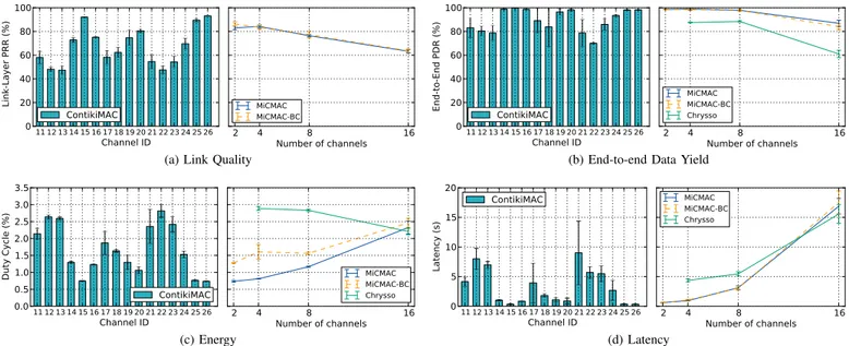
Fig. 5. Performance of MiCMAC, ContikiMAC and Chrysso with Different Channel Settings. The performance of MiCMAC with 2 to 4 channels is similar to that of ContikiMAC running on the best available channels (26, 15, 25, or 20). As the number of channels increases (to 8 or 16), worse channels are being used, and MiCMAC results in a compromise between the channels in use. Chrysso exhibits low PDR overall, but also shows better scalability with the number of channels than MiCMAC (since MiCMAC has CSMA backoff and broadcast strobe time proportional to the number of channels).
but rather an indicator of the quality of the radio medium during a given experiment.
End-to-End Packet Delivery Ratio (PDR) Represents the transmission success rate for datagrams, computed end-to-end, from the initial sender to the network root over multiple hops. It tells how reliable the protocol is.
Duty Cycle We use duty cycle, the portion of time where the radio is turned on, as a platform-independent metric for power. It tells how energy-efficient the protocol is. We measure the duty cycle inline using Contiki’s energy profiler [23]. Latency We measure latency as the time difference between the reception of datagrams at the root and its initial trans-mission time from the originator. We base the measurement on testbed timestamps of the serial output from the sender and receiver nodes. For some applications (e.g., alarm, live monitoring), minimizing end-to-end latency is a key goal.
We run each experiment for a duration of 60 minutes and extract our results from the last 30 minutes, where the topology is most stable. Note that we observe an initial network setup phase of about 10 minutes in general, after which RPL keeps doing minor topology adjustments but the overall performance has converged. We set the transmission power to 0 dBm. We repeat each experiment at least 3 times. Data points are averaged over all iterations, error bars represent standard deviation across the iterations.
B. Effect of Multi-channel on Performance
We first run ContikiMAC on all individual 16 channels of 802.15.4 to get a picture of each channel’s quality, and to measure how RPL/ContikiMAC operate in different chan-nel conditions. From this experiment, we sort the chanchan-nels by decreasing average PRR. We then run the multi-channel protocols (MiCMAC, MiCMAC-BC, Chrysso), with 2, 4, 8 or
16 channels (we always pick the N best channels according to the aforementioned single-channel PRR measurements). It should be mentioned that these per-channel measurements are not strictly required for MiCMAC to operate, but we do them for the sake of fair comparison.
Figure 5a shows the average link PRR obtained in different experiments. It shows that the testbed is subject to WiFi interference, with lower PRR at the most common WiFi channels, and with the best PRR at the 4 WiFi-free channels: 15, 20, 25, and 26. Those are the 4 channels we use in further 4-channel experiments.
In reliability (Figure 5b) and duty cycle (Figure 5c), MiCMAC keeps the overhead over the best ContikiMAC results at a reasonable level, in spite of the increased cost for broadcast (for instance, channel 15 yields a 99.7% PDR and 0.75% duty cycle vs. 99%, 0.81% duty cycle for MiCMAC with 4 channels). MiCMAC suffers from a latency increase from 0.35s (ContikiMAC, channel 15) to .91s (MiCMAC, 4 channels). This is explained by the longer CSMA back-off that MiCMAC uses, multiple of the number of channels in use. When using 16 channels, the performance degrades due to using all (including bad) channels and due to increased cost of broadcast and channel-lock operations. MiCMAC-BC achieves performance similar to MiCMAC, except in duty cycle, where the extra wakeup on a broadcast channel increases the baseline consumption (the trade-offs of using a dedicated broadcast channels are evaluated in more details in §IV-E).
In contrast, Chrysso suffers from a reduced data yield (about 88% for 4 and 8 channels, and close to 60% for the case of 16 channels), and results in higher duty cycle than MiCMAC. The reduced data yield is attributed to the occurrence of asymmetric links between child nodes and their parents on the testbed. Especially, when a child node does not receive acknowledgments for its data packets on account of link asymmetry, it eventually executes the channel scanning
routine to find a new neighbor. As the decision to perform channel scanning is deferred until the control loops fail to re-connect the child to the routing tree, the child node incurs a significant delay that directly affects data yield. Likewise, the higher duty cycle achieved by Chrysso is attributed to the frequent use of channel scanning on account of asymmetric links. Overall, we find that MiCMAC outperforms Chrysso on all the three metrics.
Our experiments show that the set of channels used has tremendous impact on performance. Although MiCMAC would still have a good chance of communication due to channel hopping, we would recommend to carefully profile every individual channel in pre-deployment tests. In our results for example, where the 4 WiFi-free channels show much better performance than others, MiCMAC sees its performance degrade when using more than 4 channels. Performing inline channel blacklisting would be a possible extension of MiC-MAC, but this would require some extra control traffic for nodes to notify their neighbors upon every blacklist update.
Overall, this series of experiments shows that MiCMAC operates over multi-channel with little overhead, with end performance similar to that of ContikiMAC experiments over the same set of channels.
C. Resilience to External Interference
We evaluate the efficacy of MiCMAC when it comes to recovering from external interference. To experiment in controlled environment, we use WiFi-free channels only, i.e., 15, 20, 25, and 26, but inject emulated WiFi interference using the JamLab tool [24] over a single channel (we pick the best channel, 26). We set 4 nodes (id #2, #4, #5, and #12) close to the root to generate WiFi interference following JamLab’s implementation of the Garetto model [24], emulating an access point with 25 hosts (which results in a measured loss rate of about 81% for nodes next to the interference source). We use 4 nodes in order to widen the range of interference in a setting where all nodes in the testbed use the same transmission power of 0 dBm. We periodically turn the interferer nodes on and off at a 5 minute interval to observe how different protocols react to changes between bursty and noiseless environment.
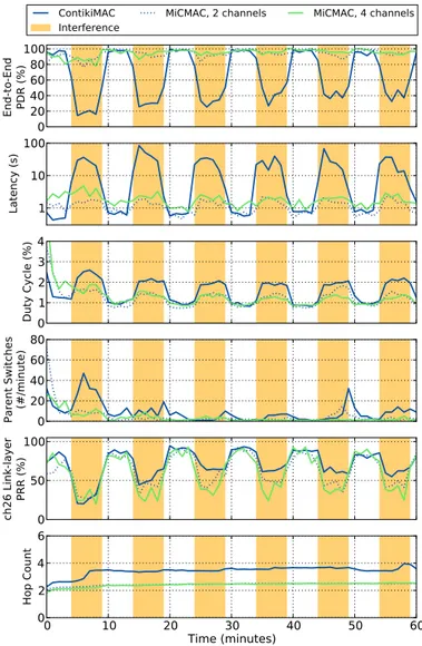
Figure 6 shows how different metrics evolve during the course of the experiment, for ContikiMAC and for MiCMAC in 2-channel or 4-channel settings. A first observation is that MiCMAC, even when using no more than 2 channels, keeps its reliability high during interference periods (above 90%), while ContikiMAC drops down to around 40% PDR. This is ex-plained by channel diversity: when losses occur on a channel, the next transmission attempt, on a different channel, does not necessarily suffer from the same interference. Consequently, losses are largely hidden from the routing layer, resulting in few RPL parent switches, and a more stable topology. In contrast, ContikiMAC compensates losses with link-layer retransmissions, increasing duty cycle and latency. Note that RPL routing protocol reacts accordingly: certain links are classified as bad (high ETX), forcing nodes to switch parent. As a result, better links are used, which explains the increase of PRR on channel 26 during the course of the experiment. A downside of this topology adaptation is increased hop count, which occurs during the first interference period and only in ContikiMAC case. 0 20 40 60 80 100 EndTt oTEnd PDRaw3# ContikiMAC Interference MiCMAC5a2achannels MiCMAC5a4achannels 1 10 100 Latencyaws# 0 1 2 3 4 DutyaCycleaw3# 0 20 40 60 80 ParentaSwitches wLpminute# 0 50 100 ch26 aLinkTlayer PRRaw3 # 0 10 20 30 40 50 60 Timeawminutes# 0 2 4 6 HopaCount
Fig. 6. Effect of External Interference on ContikiMAC and MiCMAC. MiCMAC increases robustness to external interference through channel hop-ping, resulting in higher packet delivery ratio, lower latency and duty cycle than ContikiMAC. MiCMAC hides most of the link losses to the upper layer, and does not force RPL to react during interference (fewer parent switches and no change in hop count).
This experiment shows that unlike ContikiMAC, MiCMAC successfully recovers from interference by hiding link losses to upper layers, keeping the topology stable and application-layer metrics high.
D. Topology
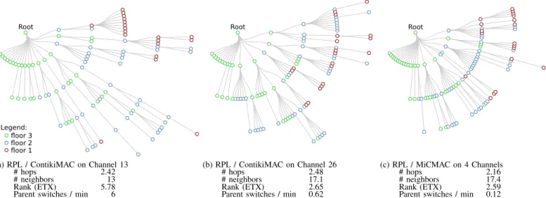
As found in the above experiments, channel conditions affect the routing topology and the resulting hop count. Fig-ure 7 gives a closer look at the resulting topology in different scenarios.
Figure 7a shows a sample (and typical) topology obtained when running ContikiMAC on channel 13, i.e., the worst observed channel. The resulting topology has up to 6 hops. In contrast, when running on the best channel (26), the topology is more compact, with only 4 hops, because the nodes are able to reach further (see Figure 7b). Interestingly, running MiCMAC over 4 channels (see Figure 7c) results in an even more compact topology, with now only one node 4 hops away
floor 3 floor 2 floor 1 Root
Legend:
(a) RPL / ContikiMAC on Channel 13
# hops 2.42
# neighbors 13
Rank (ETX) 5.78
Parent switches / min 6
Root
(b) RPL / ContikiMAC on Channel 26
# hops 2.48
# neighbors 17.1
Rank (ETX) 2.65
Parent switches / min 0.62
Root
(c) RPL / MiCMAC on 4 Channels
# hops 2.16
# neighbors 17.4
Rank (ETX) 2.59
Parent switches / min 0.12
Fig. 7. RPL Topology Obtained with Different Channel Settings. When running on top of ContikiMAC in bad channel conditions (channel 13, PRR of 42.8%), RPL builds a topology with up to 6 hops. On a good channel (channel 26, PRR of 93%), nodes can reach farther as no more than 4 hops are required to connect the network. MiCMAC, through channel diversity, increases the number of usable links, making it possible for RPL to build an even more compact topology, with most nodes in the [1-3]-hop range.
0.3 0.5 1.1 2.2 4.4 8.7 17.5 TrickleBMaxBPeriodB(min) 0 10 20 30 40 50 60 ProportionBofBBroadc astsB (-) MiCMACMiCMAC-BC
(a) Broadcast Proportion of Total Traf-fic 0.3 0.5 1.1 2.2 4.4 8.7 17.5 TrickletMaxtPeriodt(min) 90 92 94 96 98 100 End-t o-endtPDRt( A) MiCMAC MiCMAC-BC
(b) End-to-end Data Yield
0.3 0.5 1.1 2.2 4.4 8.7 17.5 Trickle Max Period (min) 0 1 2 3 4 5 Duty Cycle (%) MiCMAC MiCMAC-BC (c) Energy 0.3 0.5 1.1 2.2 4.4 8.7 17.5 Trickle Max Period (min) 0.0 0.5 1.0 1.5 2.0 2.5 Latency (s) MiCMAC MiCMAC-BC (d) Latency
Fig. 8. MiCMAC with and without a Broadcast Channel in more or less Broadcast-intensive Scenarios. The dedicated broadcast channel proves useful in broadcast-intensive cases, where it saves energy (cheaper strobing) and improves latency (less internal interference). With less frequent broadcasts (e.g. Trickle max period of 17.5 seconds), both protocols perform similarly except in energy, where the broadcast channel costs more than it saves.
from the root. This is explained by channel diversity, which increases the number of usable links due to different signal propagation obtained when hopping to a new channel. Note that channel diversity also leads to a more stable topology, as reflected by the reduced number of parent switches. This behavior helps MiCMAC reaching high performance, both under interference and in good channel conditions.
0.3 0.5 1.1 2.2 4.4 8.7 17.5 Trickle Max Period (min) 0 1 2 3 4 5 Duty Cycle (%) Tx Rx MAC Wakeups (a) MiCMAC 0.3 0.5 1.1 2.2 4.4 8.7 17.5 Trickle Max Period (min) 0 1 2 3 4 5 Duty Cycle (%) Tx Rx MAC Wakeups (b) MiCMAC-BC Fig. 9. Energy Profiles of MiCMAC with and without Broadcast Channel. With a dedicated broadcast channel and in broadcast-intensive scenarios, the reduced cost for broadcast transmissions outweighs the overhead of checking an extra channel at every wakeup.
E. Optimizing for Unicast vs. Broadcast
We finally look at the tradeoff of running MiCMAC with or without a dedicated broadcast channel, under both broadcast-intensive or unicast-broadcast-intensive settings. To this end, we vary the maximum interval of the RPL beaconing (based on a so-called ”Trickle” timer), within the range 214ms (0.3 min) to 220ms (17.5 min) (the latter being RPL’s default). As Figure 8a shows, this results in broadcasts constituting from about 50% of the overall traffic (when the Trickle max period is 0.3 min) down to about 2.5% (with Trickle max period of 17.5 min).
In broadcast-intensive scenarios (Trickle max period be-tween 0.3 min and 1.1 min), MiCMAC-BC performs best: its cheaper broadcast strobing length reduces contention and energy use. The crossing point between MiCMAC and MiCMAC-BC is at a Trickle max period of about 1 min, i.e., in a setting where 25% of the overall traffic is broadcast. This holds for PDR (Figure 8b), Duty Cycle (Figure 8c) and Latency (Figure 8d). In unicast-intensive scenarios (Trickle max period above 1.1 min), MiCMAC-BC performs similarly to MiCMAC in PDR and latency but results in a higher duty cycle. Looking at where energy is spent in more details
(Figure 9), we see that MiCMAC-BC have a more expensive wakeup as it has to check the broadcast channel periodically. Another fact that is worth noting when looking at the Tx/Rx ratio in Figure 9 is MiCMAC-BC occupies the channel less than MiCMAC does. This is explained by shorter broadcast strobes and shorter channel-lock strobes as both of them happen on one channel only. This could be exploited to minimize interference with nearby networks.
V. CONCLUSION
We design MiCMAC, a channel hopping extension to low-power listening. The asynchronous and unscheduled nature of MiCMAC makes it practical in low-power IP scenarios. We implement our protocol in Contiki and run it in a 97-node testbed, running a complete low-power IPv6 stack, with RPL at the routing layer. MiCMAC achieves performance that makes it suitable in very demanding scenarios, conciliating 99% end-to-end reliability, sub-percent duty cycle and sub-second latency. Our experiments with injected external interference show that MiCMAC hides losses from the routing layer, resulting in a more stable topology. It maintains high reliability even during heavily interfered periods, where ContikiMAC drops its delivery ratio below 40%.
ACKNOWLEDGMENT
This research has been supported by SSF and the EC projects with contract number FP7-ICT-2011.1.3-288879 (CALIPSO) and INFSO-ICT-317826 (RELYonIT).
REFERENCES
[1] B. Azimi-Sadjadi, D. Sexton, P. Liu, and M. Mahony, “Interference ef-fect on ieee 802.15. 4 performance,” in Proceedings of 3rd International Conference on Networked Sensing Systems (INNS), Chicago, IL, 2006. [2] C. A. Boano, T. Voigt, N. Tsiftes, L. Mottola, K. R¨omer, and M. A. Z´u˜niga, “Making sensornet mac protocols robust against interference,” in Proceedings of the 7th European conference on Wireless Sensor Networks, ser. EWSN’10. Berlin, Heidelberg: Springer-Verlag, 2010, pp. 272–288. [Online]. Available: http: //dx.doi.org/10.1007/978-3-642-11917-0 18
[3] T. Watteyne, A. Mehta, and K. Pister, “Reliability through frequency diversity: why channel hopping makes sense,” in Proceedings of the 6th ACM symposium on Performance evaluation of wireless ad hoc, sensor, and ubiquitous networks, ser. PE-WASUN ’09. New York, NY, USA: ACM, 2009, pp. 116–123. [Online]. Available: http://doi.acm.org/10.1145/1641876.1641898
[4] T. Watteyne, S. Lanzisera, A. Mehta, and K. S. J. Pister, “Mitigating multipath fading through channel hopping in wireless sensor networks,” in ICC. IEEE, 2010, pp. 1–5.
[5] T. I. 802.15.4e Task Group, “Ieee standard for local and metropolitan area networks–part 15.4: Low-rate wireless personal area networks (lr-wpans) amendment 1: Mac sublayer,” IEEE Std 802.15.4e-2012 (Amendment to IEEE Std 802.15.4-2011), April 2012.
[6] S. Duquennoy, O. Landsiedel, and T. Voigt, “Let the Tree Bloom: Scalable Opportunistic Routing with ORPL,” in Proceedings of the International Conference on Embedded Networked Sensor Systems (ACM SenSys 2013), Rome, Italy, Nov. 2013.
[7] M. Doddavenkatappa, M. C. Chan, and A. Ananda, “Indriya: A Low-Cost, 3D Wireless Sensor Network Testbed,” in Proceedings of the Con-ference on Testbeds and Research Infrastructures for the Development of Networks & Communities (TridentCom), 2011.
[8] V. Iyer, M. Woehrle, and K. Langendoen, “Chrysso - a multi-channel approach to mitigate external interference.” in SECON. IEEE, 2011. [9] B. Raman, K. Chebrolu, S. Bijwe, and V. Gabale, “PIP: A
Connection-Oriented, Multi-Hop, Multi-Channel TDMA-based MAC for High Throughput Bulk Transfer,” in Proceedings of the International Confer-ence on Embedded Networked Sensor Systems (ACM SenSys), Z¨urich, Switzerland, 2010.
[10] C. Liang, J. Liu, L. Luo, A. Terzis, and F. Zhao, “Dcnet: A high-fidelity data center sensing network,” in Proceedings of the International Conference on Embedded Networked Sensor Systems (ACM SenSys), 2009.
[11] Y. Wu, J. A. Stankovic, T. He, and S. Lin, “Realistic and efficient multi-channel communications in wireless sensor networks,” in INFOCOM 2008. The 27th Conference on Computer Communications. IEEE. IEEE, 2008, pp. 1193–1201.
[12] H. K. Le, D. Henriksson, and T. Abdelzaher, “A practical multi-channel media access control protocol for wireless sensor networks,” in Proceedings of the 7th international conference on Information processing in sensor networks. IEEE Computer Society, 2008, pp. 70–81.
[13] O. D. Incel, P. Jansen, and S. Mullender, “Mc-lmac: A multi-channel mac protocol for wireless sensor networks,” Centre for Telematics and Information Technology University of Twente, Enschede, The Netherlands, Tech. Rep. TR-CTIT-08-61, 2008.
[14] Y. Kim, H. Shin, and H. Cha, “Y-mac: An energy-efficient multi-channel mac protocol for dense wireless sensor networks,” in Proceedings of the 7th international conference on Information processing in sensor networks, ser. IPSN ’08. Washington, DC, USA: IEEE Computer Society, 2008, pp. 53–63. [Online]. Available: http://dx.doi.org/10.1109/IPSN.2008.27
[15] J. Borms, K. Steenhaut, and B. Lemmens, “Low-overhead dynamic multi-channel mac for wireless sensor networks,” in EWSN, 2010, pp. 81–96.
[16] L. Tang, Y. Sun, O. Gurewitz, and D. B. Johnson, “Em-mac: a dynamic multichannel energy-efficient mac protocol for wireless sensor networks,” in Proceedings of the Twelfth ACM International Symposium on Mobile Ad Hoc Networking and Computing, ser. MobiHoc ’11. New York, NY, USA: ACM, 2011, pp. 23:1–23:11. [Online]. Available: http://doi.acm.org/10.1145/2107502.2107533 [17] S. Bhadra, S.-H. Choi, Y. Sun, and X. Lu, “Demo: Achieving a
10x lifetime increase with ieee 802.15.4e motes,” in Proceedings of the International Conference on Embedded Networked Sensor Systems (ACM SenSys). New York, NY, USA: ACM, 2011, pp. 375–376. [18] A. Dunkels, “The ContikiMAC Radio Duty Cycling Protocol,” Swedish
Institute of Computer Science, Tech. Rep. T2011:13, 2011.
[19] M. Kovatsch, S. Duquennoy, and A. Dunkels, “A Low-Power CoAP for Contiki,” in Proceedings of the Workshop on Internet of Things Technology and Architectures (IEEE IoTech 2011), Valencia, Spain, Oct. 2011.
[20] D. E. Knuth, The art of computer programming, volume 2 (3rd ed.): seminumerical algorithms. Boston, MA, USA: Addison-Wesley Long-man Publishing Co., Inc., 1997.
[21] T. Winter (Ed.), P. Thubert (Ed.), and RPL Author Team, “RPL: IPv6 Routing Protocol for Low power and Lossy Networks,” Mar. 2012, rFC 6550.
[22] O. Gnawali, R. Fonseca, K. Jamieson, D. Moss, and P. Levis, “Col-lection Tree Protocol,” in Proceedings of the Conference on Embedded Networked Sensor Systems (ACM SenSys), 2009.
[23] A. Dunkels, F. ¨Osterlind, N. Tsiftes, and Z. He, “Software-based On-line Energy Estimation for Sensor Nodes,” in Proceedings of the Workshop on Embedded Networked Sensor Systems (IEEE Emnets), 2007. [24] C. Boano, T. Voigt, C. Noda, K. R¨omer, and M. Z´u˜niga, “JamLab:
Augmenting Sensornet Testbeds with Realistic and Controlled Interfer-ence Generation,” in Proceedings of the 10th international conferInterfer-ence on information processing in sensor networks (IPSN), 2011.