ViP Lesson Learned
Implementing and Using the ViP
Simulator Platform at Scania
www.vipsimulation.se
ViP PM 2016-5
Authors
Matteo Manelli, Scania
Rickard Leandertz, Scania
ViP PM 2016-5
ViP Lesson Learned
Implementing and Using the ViP
Simulator Platform at Scania
Authors
Matteo Manelli, Scania
Rickard Leandertz, Scania
Stas Krupenia, Scania
Cover picture: Stas Krupenia Reg. No., VTI: 2014/0660-8
ViP PM 2016-5
Preface
In April 2011, Scania conducted an internal review of the capability of their existing driving simulator. The review concluded that Scania’s simulator was of limited value, due to the simulation and control software being out of date, and consequently it was sufficient for only one type of test (Lane Change Tests).
In response to the review, it was proposed that Scania should acquire new simulator software that would facilitate user tests involving cognitive-motor tasks, and driver security. Additionally, with the new capability, it should be possible to conduct user studies involving tests of everything from hardware to vehicle performance.
Short term and long term goals for the improved simulator capability were defined. Based on the review, and the identified goals, several conclusions were made regarding both functional and technical requirements. The initial requirements were that Scania acquire a vehicle simulator with a simple truck model, a network communication for real-time data from a (simulated) moving vehicle, and a sample map with a road, a simple environment, and a few related objects (traffic sign, moose, etc.).
As Scania is one of the parties in the ViP competence centre, it was natural for Scania to exploit the capabilities of the centre to improve their own capability and to meet their goals as defined above. Thus, the project Lesson learned from the development of SimulaTor – LL SimulaTor was carried out by Scania within the ViP Driving Simulation Centre (www.vipsimulation.se). ViP is financed by the ViP partners and the Swedish Governmental Agency for Innovation Systems (VINNOVA).
Photos in the report Stas Krupenia. Södertälje, July 2016
Stas Krupenia
Quality review
Peer review was performed on 23 September 2016 by Jonas Jansson, VTI. Stas Krupenia has made alterations to the final manuscript of the report. The ViP Director Lena Nilsson examined and approved the report for publication on 5 December 2016.
ViP PM 2016-5
Table of contents
Executive summary ...9
1. Introduction ...11
2. Background ...12
3. Planning and execution ...13
4. Adaptation of work ...14 4.1. Control room ...14 4.2. Cabin ...17 4.3. Kernel ...19 4.4. Visualization ...19 4.5. Cockpit ...19 4.6. Sound ...19 4.7. Vehicle dynamics ...19
5. Interaction with ViPForge ...20
5.1. Material taken from ViPForge ...20
5.2. Materiel delivered to ViPForge ...20
6. Project examples ...21
6.1. Project 1: Digital Mirror Augmented Reality Content ...21
6.2. Project 2: Methods for Designing Future Autonomous Systems ...22
6.3. Project 3: Authority Transition Interface ...23
7. Lesson learned ...25 7.1. Documentation ...25 7.2. Incremental upgrade ...25 7.3. Regulations...25 7.4. Scenario development ...25 7.5. Hardware integration ...25
7.6. Using real truck hardware ...26
7.7. Driver monitoring ...26
7.8. Running scenarios ...26
7.9. Graphic fidelity ...26
7.10. Data analysis ...26
8. Advice for future implementations ...27
8.1. Phased upgrades ...27
8.2. Support ...27
8.3. Developer experience ...27
8.4. 3D models and a truck dynamics model ...27
9. Conclusions ...28
References ...29
Abbreviations
3D Three-dimensional space.
Alsa Advanced Linux Sound Architecture, an API for sound card device drivers. API Application Programming Interface.
AR Augmented Reality.
Arduino Open-source hardware platform for digital devices and interactive objects. DAQ Data Acquisition.
DeDT Previous ViP project which led to an editor for creating road logics. DeDT2 Previous ViP project which was a further development of the DeDT editor. DirectX Collection of application programming interfaces (APIs) for handling
multimedia tasks. DVI Digital Visual Interface.
FFI Forskningsprogrammet Fordonsstrategisk Forskning och Innovation (Research programme for Strategic Vehicle Research and Innovation).
Greit Visualization component based on the game engine Unity3D. GUI Graphical User Interface.
HDMI High-Definition Multimedia Interface.
HiQ A leading Nordic company delivering simulation solutions. HMI Human Machine Interaction.
KVM Keyboard, Video monitor, Mouse. MMDE Multimodal Display Engine.
OpenAL Open Audio Library, a cross-platform audio API for rendering of 3D audio. OpenDRIVE Open format specification to describe the logic of a road network.
OpenSceneGraph Open source 3D graphics application programming interface. SimulaTor Scania’s truck simulator.
SIREN Simulator Sound Renderer.
ViP Driving Simulation Centre, a competence centre administered by VTI.
VISIR Visual Simulation of Road or Railway, visualization component used in the ViP platform.
VTI Swedish National Road and Transport Research Institute. XODR File extension used for the OpenDrive format.
ViP PM 2016-5
List of figures
Figure 1. Floor plan of Simulator and Control Room. ... 15
Figure 2. Control Room Operating Area. ... 15
Figure 3. Control Room Computer Rack. ... 16
Figure 4. KVM (Keyboard, Video monitor, Mouse) remote control and switch. ... 17
Figure 5. View of SimulaTor from left side. ... 18
Figure 6. View of SimulaTor from front side. ... 18
Figure 7. Solutions generated in the Digital Mirrors Augmented Reality project (Payandehmehr & Placzkowska, 2015). ... 21
Figure 8. Summary of MODAS project Full Windshield Head Up Display. ... 22
Figure 9. Representation of the Authority Transition Interface (Belderbos, 2015). ... 23
ViP PM 2016-5 9
ViP Lesson Learned: Implementing and Using the ViP Simulator Platform at Scania
by Matteo Manelli1, Rickard Leandertz1 and Stas Krupenia1 1 Scania CV AB
Executive summary
In 2011 Scania conducted an internal investigation of their driving simulator capability. The analysis found that the capability was insufficient for current and upcoming needs. In response, a number of simulator goals were defined and an analysis of potential solutions was conducted.
To reach the goals Scania decided to create a driving simulator composed of their existing hardware and ViP’s simulator core (software) adapted to their local needs. Adaptation and integration of the ViP simulator core into Scania’s hardware commenced in Q2 2012 and was completed in Q4 2012. The first user study in the new simulator took place immediately following completion of the adaption and integration. Since then, the simulator has been used frequently for test and development purposes, and undergoes continuous improvement. The experiences of the integration and adaptation work are described in this report, and are intended to guide the coming development of the ViP platform.
ViP PM 2016-5 11
1.
Introduction
Based on an internal review 2011, Scania identified their existing simulator capability as being insufficient for the organization’s current (then) and future needs. In response, a further analysis was conducted to identify for what projects (or goals) an upgraded simulator capability would be required. Additionally, the functional capability was defined. To meet this capability, a decision was made to build a new simulator based on the ViP platform. The ViP software platform was required to be integrated with the existing hardware platform at Scania. Thus, installing the ViP software at Scania required some unique integration effort.
A significant part of the project was implemented by HiQ at VTI’s premises in Linköping. Software and hardware integration was based on the VTI hardware/software platform, and then transferred to Scania’s truck simulator in Södertälje.
During 2012 the new driving simulator (SimulaTor) was built at Scania. This simulator was the first non-VTI simulator to be built on the ViP platform. However, a previous ViP project involved the integration of the VTI software (excluding the vehicle model) in the simulator at Saab Automobile in Trollhättan (Bergström & Nåbo, 2012). During the development of SimulaTor the ViP software platform was adapted to match a new fixed-based Scania simulator. During this process, a large amount of knowledge was gained that could be valuable to the ViP consortium. In the current report, we describe the work completed as well as the lessons learned in the immediate aftermath that could be valuable for institutions wishing to repeat this process.
2.
Background
In an earlier project between Scania, HiQ Ace, and Linköping University a simulator cockpit was developed that was based on a heavily stripped cab provided by Scania. To conserve resources, it was decided that this hardware platform would be retained even though several shortcomings (compared to a full cabin) were identified.
To make sure that the development of the new platform was as smooth as possible Scania contracted HiQ to support installation and integration as HiQ was already familiar with the ViP platform. VTI personnel were sub-contracted to HiQ to provide support as required.
The planned simulator was intended to support user testing in the near and longer term. The intended goals for the short term and long term tests were defined as follows:
Goals for short term tests:
o User interface tests in realistic environment. o Driver distraction tests; doing tasks while driving. o Driver reaction tests when unexpected events occur.
o Driver attention tests; warning driver about danger during driving. Goals for long term tests:
o Testing new hardware. o Testing vehicle performance.
o Testing driver support for eco-driving.
o Testing hardware and software for platooning. o Testing new vehicle parameters.
The simulator should support rapid prototyping and developments. In other words, the goals defined above should be achieved, within each project, over a relatively short turn-around time. The intended process is that development projects request simulation and test services from the simulator.
ViP PM 2016-5 13
3.
Planning and execution
The work was planned to start in summer 2012 and be delivered by November the same year. The work was divided in two main phases; an adaptation phase in Linköping, starting in summer 2012, and a deployment phase at Scania, in November 2012. Four HiQ employees were involved, each
responsible for a specific aspect of the adaptation (vehicle dynamics, cabin, visualization, and sound). The software development at HiQ followed agile methods, with daily meetings and collaborative development. Weekly teleconferences were planned between HiQ and Scania. Occasional meetings were held in Linköping and Södertälje. The installation on site was planned to take three weeks, involving the physical connection between the cabin and the computer rack, the projector setup, calibration, and development of the first test scenario.
4.
Adaptation of work
This chapter describes the work needed to adapt the ViP software platform to fit in Scania’s simulator. The floor plan of the facility is shown in Figure 1, and a more detailed description of the system architecture is presented in Appendix 1.
4.1.
Control room
The control room consists of an operating area and the computer rack. The operating area is shown in Figure 2, which presents the following:
1. KVM monitor, for selecting which computer that is controlled by the Keyboard, Video monitor, and Mouse.
2. Monitor used to show either a. Cockpit PC
b. Vehicle PC c. Sound PC or d. Server PC.
To change what is shown on the monitor, it is necessary to use the KVM Remote Control (see Figure 4) and direct it to the Video Switch while selecting the required computer input.
3. Visual computer-04 (left wall projection), -03 (middle wall projection), -05 (right wall projection).
4. Keyboard is connected to KVM Switch.
a. The keyboard can be connected to any of the computers. To change which computer that receives the computer/mouse signals:
i. Double-press on scroll-lock on the keyboard.
ii. Your selection options will appear on the KVM monitor (1).
iii. On the KVM monitor (1), navigate between all computers. Relevant are: visual-04, -03, -05 (3), in that order. Sound-PC, Cockpit-PC (2).
5. Visual-01, -02, rear view mirrors. It was necessary to select the input on the monitor to switch between the views.
ViP PM 2016-5 15
Figure 1. Floor plan of Simulator and Control Room.
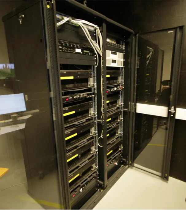
The computer rack appears as shown in Figure 3.
Figure 3. Control Room Computer Rack.
The computer rack contains the following:
• Visual 1 PC: On this we run VISIR1 to show on the Left truck mirror.
• Visual 2 PC: On this we run VISIR to show on the Right truck mirror. • Visual 3 PC: On this we run VISIR to show on the Left simulator screen. • Visual 4 PC: On this we run VISIR to show on the Centre simulator screen. • Visual 5 PC: On this we run VISIR to show on the Right simulator screen. • Sound PC: On this we run
o Multimodal Display Engine (MMDE), responsible for communication between kernel and various displays.
ViP PM 2016-5 17 o Kernel, responsible for communication between all simulator components
(VISIR, truck dynamics etc.), and also runs scenarios.
o TruckDynamics, responsible for the physics aspects of driving the truck. o SIREN2 (Andersson & Genell, 2013), responsible for outputting sound. Needs
around 3 applications running; one for engine, one for ambient, and one for events.
Cockpit PC: On this we run we translate signals from the cockpit (cabin) into a form required for the simulator kernel.
Cockpit IO: Forwards information from pedals and steering wheel to kernel. Server PC: Runs an NTP server. Used for synchronizing time between all PCs. Kernel PC: Not used.
Vehicle PC: Not used.
Amplifiers (x 2): For amplifying sound signal from computer to in-cab speakers. Sound splitters (x 2): For controlling direction of sound signals (input and output). KVM switch (Figure 4): Sending keyboard and mouse signals to selected computer. LAN switch: For wired connections to the local area network (also connected to this
switch is the Wifi Router placed on top of the rack).
Video switch: The receiver for switching what is shown on the Sound-PC/Cockpit-PC Monitor [2] via the KVM Remote Control.
Microphone Sound Box (pre-amp mixer).
KVM Remote Control (Figure 4): Used to select the computer shown on monitor 2.
Figure 4. KVM (Keyboard, Video monitor, Mouse) remote control and switch.
More detailed descriptions of all components are presented below.
4.2.
Cabin
As mentioned, it was decided to use an existing truck seating buck in SimulaTor. The buck consists of a pneumatic seat, the steering column complete with wheel and shaft, instrument cluster, and the remaining dashboard. The steering shaft was connected to a servo-motor and complementary control unit. The pedals, levers and some buttons are wired to an Input/Output board. A 5.1 surround sound system was installed around the driver’s seat. This sound system was constructed using 5-pole speaker stands positioned around the driver’s seat. Left and right mirror supports pillars were added to the sides of the dashboard.
2 SIREN is the audio engine in ViP.
Figure 5 shows SimulaTor from left side and Figure 6 shows it from the front.
ViP PM 2016-5 19
4.3.
Kernel
A simplified version of VTI’s own kernel software (vtisim) was developed. This kernel was a stripped-down version of the VTI specific code. VTI has its own vehicle model and cabin which are not used by SimulaTor. Therefore, the code that supported these elements was removed along with plugins that were not part of the official ViP simulator. The kernel was further developed with a new (vehicle dynamics class (ExtTruckDynamics), added to exchange data with the vehicle dynamics software. A new cabin handler class (ScaniaHandler) was added to exchange data with the Cockpit. These classes are Scania specific and correspond to the software and hardware developed and assembled for SimulaTor. According to the initial study description, five driving scenarios were included in the initial delivery.
4.4.
Visualization
Revision 476 of VISIR3 was downloaded from VipForge4 and compiled. A road description file
(XODR) that initially represented the 2-lane highway between Linköping and Norrköping was modified to become a 3-lane highway. Some 3D models of vehicles were added and could be used as randomized traffic or event-based actors (i.e. scripted to respond to certain specific pre-planned events). Five different VISIR applications were configured, each showing a different point of view, namely the three main screens (left, front, right) and the two rear view mirrors.
4.5.
Cockpit
The Cockpit-PC was equipped to support data acquisition from the cabin via a Data Acquisition (DAQ) card (Advantech PCI-1710U). The Baldor FlexDriveII mounted in the cabin is controlled via serial communication over port COM1. The ViPForge software “VTI Joystick Relay” was modified to read the pedals’ and levers’ statuses from the cabin. Additionally, a force feedback algorithm was implemented such that forces can be applied to the rotation of the steering wheel, in much the same way as in a real vehicle. The instrument cluster presented speed and engine speed information via a separate Flash application called “ScaniaDashBoard”.
4.6.
Sound
A sound card (RME HDSP 9632) was installed in the Sound-PC. Since the ViPForge software
“SIREN”5 (Andersson & Genell, 2013) uses the OpenAL6 sound engine, the OpenAL drivers had to be
configured. SIREN was modified to avoid the overlapping of certain sounds (e.g. turning indicator sounds with different patterns). The position of sounds was extracted from the Kernel coordinate system. However, some work was needed to correctly align the location of the sound and the location of the simulated event. This enabled more accurate positioning of sounds within a 3D space (i.e. if a car overtakes on the left side, then the sound appears to come from the left side). Although this functionally was included in the initial delivery, it was improved internally within Scania.
4.7.
Vehicle dynamics
The only application that did not exist in the ViP platform was the vehicle model. The vehicle
dynamics had to be developed in the absence of an existing platform. The delivered vehicle model was a generic application that had configurable speed and gear levels. It did not support any frictional or gravitational resistance (e.g. from rolling on the road, or aerodynamic resistance).
3 VISIR is the graphical engine in the ViP platform. 4 https://www.vipforge.se
5 SIREN is the audio engine in ViP. 6 https://openal.org
5.
Interaction with ViPForge
ViP partners regularly add software updates to ViPForge. All ViP contributed software used in SimulaTor today were downloaded from ViPForge.
5.1.
Material taken from ViPForge
The downloaded material from ViPForge consists of simulator specific software such as SimKernel, VISIR, SIREN and the common software platform. These are the crucial parts of the simulator and SimulaTor would not function without it.
In addition, DeDT2 (Stenmarck, Leandertz & Blissing, 2016) and Greit (Andhill, Blissing & Källgren, 2014) have been downloaded. DeDT2 was used for constructing scenario roads, and Greit was
evaluated for its potential improvements on graphical elements. Additionally, 3D models from the early DeDT (Alm, Hagemann & Andhill, 2012) project were used in several initial projects.
5.2.
Materiel delivered to ViPForge
With the purpose of unifying the simulator under the same operating system SIREN was modified to work with Windows OS. This required changing the API to DirectX instead of Linux-based Alsa. This version of SIREN was added to ViPForge in 2015.
ViP PM 2016-5 21
6.
Project examples
In the previous sections, a description of the (then) state of the SimulaTor has been presented. In the current chapter, we describe some of the projects in which the SimulaTor has been used. Based on this experience, some of the lessons we have learned, regarding implementation and use of the SimulaTor for supporting simulation based design, are documented in chapter 7.
6.1.
Project 1: Digital Mirror Augmented Reality Content
The Driver Vehicle Interaction Group at Scania hosted two students who completed their Master’s thesis project on Digital Mirrors (Payandehmehr & Placzkowska, 2015). Specifically, they
investigated what supplementary information (Augmented Reality, AR) can be used to increase the driver’s awareness of the surroundings.
The general rationale is that, by replacing physical mirrors (located on the cab exterior) with digital mirrors (located inside that cab) wind resistance can be reduced, and thus also fuel use. Coupled with the switch from physical to digital mirrors comes new opportunities for vision enhancement via supplementing the digital displays with additional information. However, the problem of visual clutter is well known within HMI design, and it is crucial to take a careful deliberate design approach to introducing new information to the digital mirrors. The purpose of the project was to test one or more concepts for adding supplementary information to the digital mirrors that would increase the driver’s awareness of the surroundings and therefore contribute to improved road safety. Specifically, the concepts were tested to assess driver performance regarding detection of obstacles in blind spots, vehicle control, and subjective opinions regarding perceived mental workload and user acceptance.
Figure 7. Solutions generated in the Digital Mirrors Augmented Reality project (Payandehmehr & Placzkowska, 2015).
The solutions generated within the project (see Figure 7) were tested in SimulaTor using ten professional commercial truck drivers. The work completed to support the testing included:
Creating simulator scenario story boards in conjunction with project team.
o The scenario design was strongly influenced by the test objectives. A key discussion item was the required number of lane changes and the behaviour of a scripted ‘sneaky’ car.
Generating new Simulator Scenarios.
o This involved creating two roads (Baseline, Concept) that included twenty lane changes each. In eight of the lane changes, a scripted ‘sneaky’ car would be present in the participants’ blind spot at the time of the required lane change.
Programming digital mirror AR overlay.
o The green/orange/red AR overlay (Figure 7) was programmed to be triggered depending on the driver action and the presence of other vehicles.
6.2.
Project 2: Methods for Designing Future Autonomous Systems
The project Methods for Designing Future Autonomous Systems (MODAS; Krupenia et al., 2014) was a 23-month project (1st February 2013 to 31st December 2014) funded by the Strategic Vehicle Research and Innovation (FFI) funding scheme (2012-03678). In brief, the challenge set within the project was; if a highly autonomous truck was technically possible, what would be the best possible driver environment from a driver’s perspective?
Specifically, there were four project goals:
1. Create a system development method for future (non-existent) systems design. 2. Apply the method to develop a prototype cab for a highly autonomous truck. 3. Develop a method for assessing user acceptance of the concept.
4. Develop a method for assessing performance in highly autonomous trucks. The solutions developed for the MODAS project included:
3D audio display.
Head Up Display (see Figure 8). Tablet computer for touch input. Full screen Instrument Cluster.
Figure 8. Summary of MODAS project Full Windshield Head Up Display.
To assess the MODAS solutions, three rounds of simulator testing were conducted. The work completed to support the testing included:
Integrating new hardware.
o Integration of the tablet as a new touch input.
ViP PM 2016-5 23 Creating simulator scenario story boards in conjunction with project team.
o The project would request certain events in the scenario. Where possible all requests were included, however, if requests were not possible to implement or too time consuming they were removed or modified.
Generating new Simulator Scenarios. Five scenarios were created: o Highway. Entering a highway and selecting a platoon to join.
o Highway. Highway platoon driving and encountering a wobbly motorbike. o Highway. Highway platoon driving and encountering a traffic accident. o Forrest road. Scenic route.
o Forrest road. Direct route. Conduct testing with drivers.
o Product design Iteration 1 testing. o Product design Iteration 2 testing. o Product design Iteration 3 testing. Delivery of cleaned data to project team.
6.3.
Project 3: Authority Transition Interface
The Authority Transition Interface was developed as part of a Master’s thesis project that sought to develop solutions to support the safe, efficient, and pleasurable handover of control from an autonomously driven truck back to the driver (Belderbos, 2015). Key to this project was to create a handover (authority transition) interface that would support a rapid takeover of control by the driver in a complex situation. The solution developed in this project included multiple HMI components (see Figure 9).
Figure 9. Representation of the Authority Transition Interface (Belderbos, 2015).
The functionality of the concept was realized through different features which were integrated into SimulaTor. Testing was conducted with 15 professional commercial drivers.
To assess the concept that was developed in the project, significant work was conducted within SimulaTor.
This included the following: Integrating new hardware.
o Seat vibrators connected via an Arduino to the simulator kernel. o LED strip located around the windshield perimeter.
o Concept steering wheel that included: LED rim
Centre touch screen Internal vibro-motors Generating new Simulator Scenarios.
o Two qualitatively equal scenarios were created, one involving road works that triggered the handover, the other involving a broken-down vehicle.
Conduct testing with drivers.
Integration of Driver Monitoring System for data analysis. o Multiple camera system.
ViP PM 2016-5 25
7.
Lesson learned
After extensive use of the simulator following the adaptation, several lessons have been learned regarding the acquisition and use of the driving simulator.
7.1.
Documentation
Documentation of the ViP platform varies. For some parts the documentation is thorough and rather complete, while for other parts the documentation is sparse. For example, VISIR is well documented, while the kernel and SIREN are poorly documented. It is important to note that the kernel has since been documented, however, at the time of SimulaTor implementation this documentation was missing. To work with the kernel and SIREN, a trial and error approach was needed when adapting, installing, and editing components. This approach was not efficient. Effort could have been minimized with better use of the support hours from VTI developers which was not well utilized.
7.2.
Incremental upgrade
The simulator transition at Scania could have benefitted from a two-stage installation process. Since certain components already existed at Scania (e.g. physical cabin and the projectors) the simulator switch could have started with an initial software update. The cabin with projectors and additional wiring could have been changed at a separate occasion. This would have reduced risks and most likely ensured a smoother integration.
7.3.
Regulations
The need to comply with health and safety regulation should have been foreseen. Moreover, CE certification of moving parts such as the connection between steering shaft and servo-motor was required. Obtaining CE certification for all moving parts took a considerable time to complete (at additional cost to Scania). The failure to plan for this in advance meant that ‘patches’ to the simulator were required. Because they were not planned for in advance, these ‘patches’ have been sub-optimal and resulted in multiple interruptions to simulator usage.
7.4.
Scenario development
Scania is pleased with the completed adaptation. The driving simulator works well within a narrow set of requirements and is frequently used and continuously improved. Nevertheless, every new project requires a lot of effort that translates into higher cost for Scania. The ViP platform should have provided more tools to accelerate the most time-consuming tasks, such as creating maps and road networks with junctions.
Additionally, a valuable capability would be to move easily between different parts of a scenario. Currently, if the research team wants to check an event that occurs 10 minutes into the scenario, it is necessary to drive that first ten minutes. A method for jumping around within the scenarios would greatly reduce development time.
7.5.
Hardware integration
SimulaTor is mostly used for testing additional hardware in the cockpit such as LED lights, vibrators, head up displays, and other visual and haptic devices. To make this work properly a new computer and custom-made software were added. This computer handles the communication with peripheral
displays of all modalities. In SimulaTor the component is called Multi Modal Display Engine (MMDE). It was first created to communicate with Arduinos and raspberry pies to execute seat vibrations and to display messages with LED strips. This computer was not accounted for in the original setup but has become a necessary component in SimulaTor.
7.6.
Using real truck hardware
Due to the use of real truck components SimulaTor has been equipped with new computers to read CAN bus messages. The demand for testing finished components is increasing, and having more components in the same system makes this a useful addition. This need was not recognized from the beginning and could have changed the way signals were handled if considered.
7.7.
Driver monitoring
Based on the initial integration, during testing it was never possible to know what the test participant was doing during the drive (other than the view of the virtual world from the control room). For example, the participants could have been steering with their feet, and this would not be known to the research team. Additionally, two-way communication with the participant was not possible. This meant that, to start a new scenario or deliver new instructions, the researcher needed to move between the cab and the control room. Though minor, this costs time and can be disruptive to the test process. Additionally, the lack of a driver monitoring system meant that it was not possible to obtain a
permanent record of driver behaviour. Consequently, conclusions regarding interactions with certain products were based solely on subjective questionnaires and simulator log files.
7.8.
Running scenarios
The hardware and software structure of the simulator means that it is only possible to run scenarios from one computer in the control room. When running user studies, this computer becomes a bottleneck and means that no other simulator development can take place during testing. With the simulator being used heavily for testing, development time is constrained.
Additionally, it would be beneficial to be able to run scenarios from inside the cab. In this way, it becomes easier for the researcher to sit with the test participant in the cab and control the simulator. For example, if the researcher wants to explain how to behave at a certain simulator event the researcher may want to run a scenario, or part of a scenario, multiple times to ensure sufficient participant performance.
7.9.
Graphic fidelity
The realism of the simulator graphics is a weakness. The effort required to build roads and landscapes is significant given the tools available at Scania today. This could have been investigated more thoroughly prior to implementation, either finding a tool to make landscaping in OpenSceneGraph7
more simple and more detailed, or implementing another graphics engine. Additionally, using representative GPS specific locations would deliver the opportunity to export the simulator GPS coordinates to secondary mapping tools.
7.10. Data analysis
The simulator data log outputs are difficult to use. The abbreviated names for the parameters are not always intuitive, and it is difficult to obtain excerpts of data necessary for each study. Not all
parameters measured by the simulator are needed for each study. It would be beneficial to have a tool to support the selection of important data, and to have simple scripts for cleaning the data.
ViP PM 2016-5 27
8.
Advice for future implementations
8.1.
Phased upgrades
To update the simulator in small steps could be recommended. For example, a software update followed by a physical update of the cabin would reduce some of the risk associated with the move from lower to higher fidelity simulators. Ideally, a process of continuous improvement is adhered to with (minor) improvements occurring continuously.
8.2.
Support
Since the ViP platform is not fully documented it is recommended to establish a close working relationship with ViP partners especially during the start-up phase. Such support should take the form of specific joint projects, which would expose the hosting organization to potential issues. By having ViP involved in these projects, the required support would have been more immediately obvious (and immediately available).
8.3.
Developer experience
It is important to note that the development is not finished with the installation. Although some scenarios were available upon delivery, building the required scenarios and indeed much of the integration work required knowledge in C++ programming language. Thus, it is a key factor that the hosting organization have personal well versed in C++ working with the simulator.
8.4.
3D models and a truck dynamics model
There is no library of 3D models included in the ViP software platform. Such a library is needed to create credible surroundings and traffic on the roads. We suggest to consult someone with 3D
modelling competences when creating new maps or scenarios. A truck dynamics model is not included either. This is an essential part of the simulator and has to be acquired outside the ViP platform
9.
Conclusions
The SimulaTor has been an extremely valuable R&D tool for Scania. As mentioned, the simulator has been in near constant use since installation in November 2012. Most of the goals described in the “Background” (chapter 2) were achieved via the SimulaTor. We believe others can benefit from our experiences, both positive and negative, as described in the current report. Importantly, the “Lesson learned” (chapter 7) would be a valuable guide for institutions wishing to repeat the process described, and indeed for those persons working on simulator development.
ViP PM 2016-5 29
References
Alm, T., Hagemann, A., & Andhill, C. J. (2012). Driving Environment Design Tool – DeDT:
Enhanced capacity to produce complex and dynamic traffic environments. ViP publication 2012-3
(www.vipsimulation.se
)
. Linköping Sweden: Swedish National Road and Transport Research Institute (VTI).Andersson A., & Genell A. (2013). SIREN – Sound Generator for Vehicle Simulation. ViP publication 2013-3 (http://www.vipsimulation.se/). Linköping, Sweden: Swedish National Road and Transport Research Institute (VTI).
Andhill, C. J., Blissing, B., & Källgren, L. (2014). Greit – Graphics engine interface. ViP PM 2014 (www.vipsimulation.se
)
. Linköping Sweden: Swedish National Road and Transport Research Institute (VTI).Belderbos, C. (2015). Authority Transition Interface: A Human Machine Interface for taking over
control from a highly automated truck. Unpublished Master’s Thesis. Delft the Netherlands: Delft
University of Technology.
Bergström, H., & Nåbo, A. (2012). ViP SimHarm. ”White book”: Simulatorharmonisering och
förbättringar VTI-Saab/Pixcode. ViP publication 2012-1 (www.vipsimulation.se
)
. Linköping Sweden: Swedish National Road and Transport Research Institute (VTI) (in Swedish).Krupenia, S., Selmarker, A., Fagerlönn, J., Delsing, K., Jansson, A., Sandblad, B., & Grane, C. (2014). The ‘Methods for Designing Future Autonomous Systems’ (MODAS) project: Developing the cab for a highly autonomous truck. In: T. Ahram, W. Karowski, & T. Marek (Eds.). Proceedings of the
5th International Conference on Applied Human Factors and Ergonomics and Affiliated Conferences (AHFE2014), Krakow, Poland, 19-23 July, 2014.
Payandehmehr, B., & Placzkowska, M. (2015). Digital Mirrors: Supplementary information to
increase driver's awareness of surroundings. Unpublished Master’s Thesis. Stockholm Sweden:
Royal Institute of Technology (KTH).
Stenmarck, M., Leandertz, R., & Blissing, B. (2016). Driving Environment Design Tool 2 – DeDT2:
Enhanced capacity to produce complex and dynamic traffic environments. ViP PM 2016-3
(www.vipsimulation.se
)
. Linköping Sweden: Swedish National Road and Transport Research Institute (VTI).ViP PM 2016-5 31
Appendix 1: System Architecture of SimulaTor
Hardware architecture
The following diagram (Figure 10) presents the hardware architecture of the simulator.
Figure 10. Hardware architecture of SimulaTor at Scania.
Software architecture
VTIsim
This is the core software of the simulator system. It executes the scenarios and synchronizes with the vehicle dynamics, the cockpit, the sound engine, and the visualization software. It also handles data logging.
Truck dynamics
This software implements the vehicle dynamics model. It is a generic application that has configurable speed and gear levels. It does not support any frictional or gravitational resistance. It has a GUI for controlling the vehicle, facilitating the debugging of scenarios without using the cockpit.
Cockpit
This software handles the inputs from the cabin (pedals, steering wheel, and levers), implements the force feedback system, and visualizes data in the instrument cluster.
SIREN
This is the sound engine. It uses OpenAL sound library for the rendering of multichannel three-dimensional positional audio.
VISIR
This is the visualization software. It creates 3D environments from OpenDrive8 road network files
(xodr) and from additional landscape description file (xml). It synchronizes the 3D scene with the scenario executed by the kernel.
8 http://www.opendrive.org