http://www.diva-portal.org
This is the published version of a paper published in Reliability Engineering & System
Safety.
Citation for the original published paper (version of record):
Kang, E-Y., Enoiu, E P., Marinescu, R., Seceleanu, C., Schnobbens, P Y. et al. (2013)
A Methodology for Formal Analysis and Verification of EAST-ADL Models
Reliability Engineering & System Safety, 120(Special Issue): 127-138
https://doi.org/10.1016/j.ress.2013.06.007
Access to the published version may require subscription.
N.B. When citing this work, cite the original published paper.
Permanent link to this version:
domain-specific tools, e.g., Simulink or UML [5]. This impedes the possibility to construct, transform, and verify EAST-ADLmodels using formal methods such as symbolic simulation and model-checking.
To alleviate the aforementioned restriction, we propose a methodology that facilitates the verification of system function behaviors in EAST-ADL by using the UPPAAL PORTmodel-checker [7] and its simulator. Our method
is based on integrating architectural description languages with verification techniques and is tailored for EAST -ADLmodels. In order to provide automated support this method has been implemented in a tool called ViTAL1(A
Verification Tool for EAST-ADL Models using UPPAALPORT) [8]. Our approach allows the specification of the behavior inside each elementary function (block) in Timed Automata (TA) [9] and constructs a complete system behavior model by the parallel composition of local behaviors. In particular, we describe the behavior of each EAST -ADLfunction block as a UPPAALPORTTA model. A composition of function behaviors is considered a TA network
that enables one to analyze and verify the entire system using the UPPAAL PORTmodel checker. By employing
such an approach, we bridge the gap between architectural modeling and formal verification of automotive embedded systems.
The methodology builds on our previous work [10], however, in this paper we introduce the automatic translation of EAST-ADLmodels into UPPAALPORTmodels, as well as the integrated tool-support for analysis. Moreover, this
method is not restricted to a particular component model, rather, it assumes a read-execute-write semantics from the latter. We show the proposed methodology at work on an industrial prototype, the Brake-by-Wire System.
ViTAL provides model-checking of EAST-ADLdescriptions with respect to timing and functional behavioral
re-quirements. The system designer creates the EAST-ADLmodels and the execution behavior using the TA framework and checks whether a given requirement is satisfied. For this, we implement an automatic model transformation to UPPAALPORT, which enables the latter to handle EAST-ADL models as input and provide functional and timing behavior of functional blocks using TA semantics. To increase user friendliness and to align with the implementation of the EAST-ADLprofile, our integrated environment is based on Eclipse plug-ins. ViTAL contains the following: (i)
an editor for describing the behavior of EAST-ADLfunction blocks as TA models, (ii) an automated transformation
of EAST-ADLmodels to UPPAALPORTTA models, (iii) support for mapping external TA variables to external ports,
(iv) a simulator that can be used to validate the behavior of the EAST-ADLmodeled system, and (v) support for
ver-ifying reachability (can a particular goal be reached?) and liveness (can a particular goal be guaranteed to be met eventually?) properties formalized in a subset of Timed Computation Tree Logic (TCTL), the property specification language of UPPAALPORT.
This work is organized as follows: Section 2 briefly overviews EAST-ADLand UPPAALPORT. In section 3, we
introduce the Brake-by-Wire system running example. In section 4, we describe our proposed EAST-ADLmodeling
and verification approach. In section 5, the tool environment, ViTAL, is presented. In section 6, we demonstrate the applicability of our method by verifying the Brake-By-Wire system by employing ViTAL. Section 7 presents related work. We discuss future work and conclude in section 8.
2. Preliminaries 2.1. EAST-ADL
EAST-ADLis an architecture description language specified through a meta-model and implemented as a UML2
profile [4], intended to support the development of automotive embedded systems by capturing modeling related engineering information. EAST-ADLhandles various types of information including the specification of system
envi-ronment, related requirements, deployment of software and hardware resources, variability, performance constraints such as behavior and timing constraints, dependability, and V&V (Verification and Validation) related information.
The definition of an EAST-ADLsystem structure (e.g. components and their connectors), referred to as System Model, is given multiple levels of abstraction to deal with complexity control, safety, reliability, cost improvement and efficient development through MBD according to the fundamental characteristics of the system lifecycle. These levels have complete traceability between them, from a higher to a lower abstraction layer, as can be observed in Fig. 1. The support of EAST-ADLranges from this multi-level system definition to the specification of requirements
and related V&V efforts: AtVehicle Level the electronic features are described. At Analysis Level a complete
Abstractions Levels
Environment
Vehicle Level
Analysis Level
Design Level
Implementation Level
EAST-ADL
AUTOSAR
Methodology
Vehicle
Definition Phase
System
Definition Phase
Implementation
Design Phase
Figure 1. Overview of the EAST-ADLarchitecture.
representation of the abstract functional definition of features in system context is modeled. This representation is intended to capture the interfaces and behavior of the vehicle subsystems and to allow validation and verification of the integrated system or its subsystems on a high level of abstraction. AtAnalysis Level the features and re-quirements are refined by iterating the software application together with the other levels of abstraction. AtDesign Level the detailed functional definition of software is introduced according to the realized logical design. The func-tional abstraction of hardware and middleware are also presented, as well as hardware architecture being captured and function-to-hardware allocation being defined. At Implementation Level reusable code and AUTOSAR 2
compliant software and system configuration for hardware deployment are described [4].
EAST-ADL is intended as an integration framework for functionality defined in different notations and tools.
The behavioral description relies on the definition of a set of elementary functions that are executed based on the assumption of “read-execute-write” semantics (read inputs from ports, compute, and write outputs on ports). This is chosen to enable analysis and behavioral composition and make the function execution independent of internal behaviors.
2.2. UPPAALPORT
UPPAALPORTis an extension of the UPPAALtool, which supports simulation and model-checking of
component-based systems, without the usual conversion or flattening to the model of network TA. This is complemented by the Partial Order Reduction Technique (PORT) [11, 7] that UPPAAL PORT uses, to improve the efficiency of
model-checking analysis. This technique has been proposed in order to reduce the state-space explosion caused by interleav-ings, with the main idea of exploring only a relevant subset of the state-space when model-checking [12]. UPPAAL
PORTonly explores properties which preserve a subset of the full model based on independence of transitions, instead of examining all possible sequences, which would unnecessarily add to the model-checking complexity. Since the synchronization of global time restricts the independence of transitions in the timed automata framework, UPPAAL
PORTuses local time semantics to increase independence, therefore allowing the analysis of components in isolation
followed by synchronization to a shared state whenever one writes to another.
A component is defined by its interface and a timed behavior named UPPAALPORTTA. This special type of TA
[7] is defined as a timed automaton B = (N,l0,lf,VD,VC,ro,rf,E,I) where N is a finite set of locations, l0is the initial
location, lf is the final location, VDand VCare a set of data and clock variables, r0and rf are sets of initial and final
reset clocks, E is a set of edges, and I is mapping each location l to its invariant I(l). In the case of (l,g,e,r,l0)2 E ,
we write l g,e,r! l0to describe an edge from location l to l0with guard g, action update e, and reset clocks r.
In UPPAALPORTthe employed component model has transitions which are independent of actions in other
com-ponents. The performed experiments [7] suggest the use of UPPAALPORTwhen dealing with a “read-execute-write”
2AUTOSAR (AUTomotive Open System ARchitecture) is a standardized interface that defines a common software infrastructure for automotive
component model semantics. The model checker of UPPAALPORTverifies properties expressed in a subset of timed
computational tree logic (TCTL). The current input file format for UPPAALPORTis a component modeling language
[13], which describes the architectural framework for modeling real time embedded applications with particular em-phasis on automotive domain and safety concerns. In particular, this input language is used to create components and interconnections among them and supports run-to-completion semantics.
3. Running Example: Brake-By-Wire
Our Brake-by-Wire (BBW) case study is provided by VOLVO Technologies within the MBAT project [14]. The vehicle is software-simulated and the functionality of the system can be divided between sensors, actuators, and computations. The brake pedal sensor transforms the position of a pedal into a percentage of a maximum value of the brake force and the wheel sensor reads the actual wheel speed. The wheel actuator computes the brake force and the computation is divided as follows: the brake torque calculator computes the requested brake force, which is used as input in the global brake controller that calculates a basic brake force for each of the wheels. The ABS controls the wheel braking in order to prevent locking of the wheel based on the slip rate value.
The system consists of five Electronic Control Units (ECUs) connected by a network bus: a central ECU connected to the brake pedal and four ECUs connected to the wheels. The central ECU has three components: a brake pedal sensor, a component that calculates the global brake torque from the brake pedal position, and a component that distributes the global torque to the four wheels. Each wheel ECU also has three components: a sensor that measures the wheel speed, a component for the brake actuator, and an ABS controller. The ABS controller is based on a simple logic: if the slip rate of the wheel is larger than 0.2, then the brake actuator is released and no brake is applied. Otherwise, the requested brake torque decided by the central ECU is used.
The BBW system, modeled in EAST-ADL, needs thorough quality assurance up to formal verification and as
such this system has to obey strict timing requirements. The system should react timely to prevent serious accidents, for example. Timing behavior and its analysis play a crucial role in the early development of embedded and critical systems in order to avoid late detection of design flaws which negatively impacts cost: Verifying the end-to-end timing requirements, from a sensor to an actuator, must take into account the timing properties of all the components. Further details will be given in the following sections.
4. Methodology and Proposed Solutions
In this section, we describe how our approach enables formal analysis of EAST-ADL descriptions, by model-checking their behavior with UPPAALPORT, independent of platform characteristics and constraints. The verification is tailored for the Analysis Level of EAST-ADL, and is composed of the following steps, mirrored in Fig. 2: (i) Architectural Mapping, (ii) Integrating the Behavioral Formal Model, and (iii) Simulation and model checking. We discuss these steps in further detail in the following sections.
4.1. Architectural Mapping: EAST-ADLtoINTERMEDIATECOMPONENTMODEL
This architectural mapping step, M2M in our methodology roadmap (Fig. 2), is an architecture-to-architecture transformation, from EAST-ADLto an Intermediate Component Model (ICM) that can be further integrated with the formal behavioral model of TA. We work at the Analysis Level in EAST-ADL, such that we need to map essentially all the interface elements alongside the existing timing annotations.
In order to integrate the formal model of UPPAALPORTTA with EAST-ADL, we need to first perform a semantic
anchoring of the latter to a component model that obeys the read-execute-write semantics, hence preserving the informal semantics of EAST-ADL without altering its structure. Each elementary Function Prototype ( fp) has its
own logical execution and no internal concurrency, therefore it can be straightforwardly mapped to a component in the intermediate component model. We assign one component per fp element of the EAST-ADL model (e.g.,
BrakeController, ABS, in our running BBW system).
Assume an EAST-ADLcomposite EAST-ADLFunction Type defined as the following tuple:
Model Checker Simulation M2M M2M integrationintegration integration integration
Formal Analysis and Verification
Formal Analysis and Verification
behavioral description addition behavioral description addition refine refine
Intermediate Component Model (ICM) Composition Component Ports: Estring Connection Ports: Estring
Timed Automata Model EAST-ADL System Model
FunctionConnector FunctionPrototype1 Port1 Port2 FunctionPrototype2 Port3 Port4 ICM + TA Model Composition Component Behavior: TA Connection Ports: Estring refine System Requirements · Quality Requirements · Behavioral Constraints · Timing Constraints · Functional Requirements
Figure 2. Methodology Roadmap
where FPis the set of Function Prototypes ( fp) of a Function Type, DP is the set of data ports, defined as the reunion
of input ports and output ports, Con is the set of connectors, and TC is the set of the model’s timing constraints. In the case of FP=/0 and Con = /0, we obtain a primitive EAST-ADLcomponent. In our approach pictured in Fig. 2,
each Function Prototype ( fp) is associated with a formal behavior described in UPPAALPORTTA that is recalled in
section 2.2.
We also assume our Intermediate Component Model (ICM) is defined as a tuple as follows: ICM, hComp, Pin,Pout,trig, Connections, TCICMi,
where Comp is the set of components that ICM contains, Pin, and Pout are the input and output dataflow ports,
re-spectively, trig is the trigger variable that is set toTRUEby a clock component, and TCICMis the ICM’s set of timing
constraints. If Comp = /0 and Connections = /0, then ICM is a primitive component.
The architectural mapping between an EAST-ADL FunctionType and an ICM, defined as above, is a function
p : FunctionType ! ICM, which maps each function prototype fpto an ICM component, input ports to the ICM’s
component dataflow input ports, output ports to the ICM’s component dataflow output ports, connectors to the ICM’s component connections, and the Function Type’s timing constraints TC to ICM’s timing constraints, TCICM.
One or more ports and elements of EAST-ADLmodels may be realized by one port and one component of ICM, as these may have several signals or data elements per interface, which are simplified in one port and one component in our ICM representation. Function interactions within a FunctionType can be either FlowPort interactions, in which a function performs computations on provided data, or ClientServer interactions, where the execution of a service is called upon by another function. However, in this paper we consider and implement only FlowPort interactions. The triggering of each FunctionType is defined either as time-driven or event-driven on one of the input ports. There
are two types of function entities, time-discrete functions and time-continuous functions. A time-discrete function is performed after a computational delay, whereas a time-continuous function defines the transfer function from input to output, and the computation rate is infinite. However, on our mapping we do not deal with time-continuous functions, but only with time-discrete ones. The latter are invoked either in a time-triggered fashion, in which case time alone causes execution to start, or in an event-triggered manner, which is caused by data arrival or calls on the input ports. The trigger conditions are matched by those of a clock component and data type ports in ICM, respectively.
4.2. Integrating the Behavioral Formal Model: Mapping ICM to TA
In the previous sections, we have shown a straightforward mapping from the informal semantics of EAST-ADLto
the intermediate component model, ICM. Since EAST-ADLallows the use of various behavioral notations, we exploit
this feature to our advantage, and specify the function behavior by assigning an UPPAALPORTTA model to each ICM
component mapped from its corresponding FunctionPrototype( fp); in this procedure, we comply to the triggering
definition, as well as translate the execution time of each fp, and its requirements. The TA model encapsulates the
“internal behavior” of a FunctionPrototype and is used as input to the UPPAALPORTmodel-checker that we use to carry out the formal analysis and verification of functional and timing EAST-ADLproperties.
Let us consider the Intermediate Component Model (ICM) as defined in section 4.1: ICM, hComp, Pin,Pout,trig, Connections, TCICMi.
The behavior of a FunctionPrototype mapped onto a component within the set Comp of ICM is modeled as an UPPAALPORTTA, as in section 2:
TA, hL [{l?},l0,lf,VC,VD,r0,rf,E,Ii,
where L is the set of TA locations, extended with the idle location l?, l02 L is the initial location, lf 2 L is the final
location (used to model the termination of a function execution), such that no edges in E are leading out from lf. The
rest of the tuple elements have the same meaning as described in section 2. We also define the action Read(Pin)for
reading variables from Pinand W rite(Pout)for writing variables onto output ports.
The execution of the ICM behavior is determined in terms of the triggering value, which changes according to a periodic clock. When trig holds, the TA data variables in VD are updated by READ(Pin), and WRITE(Pout),
respectively, which are atomic and urgent (in the sense that time is not allowed to pass when a component reads or writes). A component is initially idle, and after performing the read action it starts executing until its internal computation is done. After completing the write action, which forwards data from the output ports via connections, the component becomes idle again. That being said, we define the mapping between ICM and TA as follows: Mapping ICM to TA. Given ICM and TA as above, the mapping rules for integrating them are:
• l? g,read,r0
! l0The read action is READ(Pin) that updates VDwith input values from Pin. The clock r0is the initial
clock reset; • lf
g,write,rf
! l?The write action is WRITE(Pout) that writes on output ports, whereas rf is the final clock reset;
• I?(l?) =true, I?=I(l) for l , l?.
The TA of a composition C, TA(C), is defined as a network of local TA. For fpi and its corresponding component
ICMi2 C, the write action in TA(ICMi) is extended to update the input ports (noted Pin. j) of a target component
ICMj2 C, according to the connections from the outports of ICMi(noted Pout.i). A connection connects a source port
p 2 Pout.ito a target port p02 Pin. j. The edges e of TA(ICMi) are explained with extended write actions as follows.
Extended Write Actions. Assume TA(ICMi)is defined as h L, l0, lf, r0, rf, VD, VC,{XW RIT Ei(e) | e 2 E},Ii, such
that the following hold:
• XW RIT Ei(l g,a,r! l0), lg,a,u! l0, if a , write.
The automata TA(C) is then the network of TA(Ci), for Ci2 C.
An environment is modeled as TAEnvin a similar way. The resulting composition is thus defined as the network
TA(C) ⇥ TAEnv, where any edge in TAEnvupdating ports Pinof C, is extended with an update W RIT E(Pout.Env). This
is similar to the adaptation of the XW RIT E action that is used to build TA(Ci)in Definition 4.2.
4.3. Simulation and Model Checking
The execution of each FunctionType in EAST-ADLis specified by UPPAALPORTTA and integrated within ICM, as described in section 4.2. The entire system (network of UPPAAL PORTTA) has its semantics given in terms of timed transition systems [15], and this whole model is verified by the UPPAALPORT model-checker. Functional requirements, timing, as well as other behavioral constraints (see Fig. 2) are formalized as safety properties in Timed Computation Tree Logic (TCTL) used by UPPAALPORT.
All requirements are derived from given system textual descriptions. On the one hand, we can verify certain delay, reaction and synchronization constraints (that is, overall behavioral constraints of a system). On the other hand, we may also check functional requirements, like particular triggering properties associated to an EAST-ADL function
block. The UPPAALPORTmodel checker verifies such functional requirements and behavioral constraints, which are
formalized in TCTL as safety properties. If UPPAALPORTreports a counter-example to a particular model, meaning
that the property under investigation does not hold for all possible system behaviors, the resulting trace could be used to refine the behavioral constraints of the system model, or modify the original EAST-ADLmodel, or the TA behavioral
description.
5. Tool-supported Modeling and Analysis
The architecture of the tool is separated into two distinct layers. The bottom layer is composed of standard editors offered by the Eclipse platform. These editors are used to design and transform the models used within the tool. Our contribution lies in the top layer, in which the ViTAL modeling and analysis approach is implemented. This section introduces the ViTAL modeling approach for EAST-ADLsystem models. In order to align UPPAAL PORTwith the implementation of the EAST-ADLprofile, we propose an integrated tool based on Eclipse plug-ins, as observed in Fig. 3. Our modeling and verification tool contains the following: an editor for TA description of the functional and timing behavior of EAST-ADLfunctional blocks, automated transformation of EAST-ADLmodels to UPPAALPORT
input model, support for mapping internal TA variables to external ports, a simulator that can be used to validate the behavior of an EAST-ADLmodeled system, and support for verifying reachability and liveness properties formalized
in a subset of TCTL. 5.1. Modeling Approach
In most cases an automotive system is composed of a large number of software and hardware vehicle functions. EAST-ADL depicts the whole automotive system from requirements specification until design and implementation.
We employ the EAST-ADLfunctional model on analysis and design level as the modeling language to specify the
structure of a system. The challenge of EAST-ADLsystem modeling on analysis and design level is to target different
system components for concepts like allocation of requirements, analyzing, and verifying functional requirements be-fore implementation. On the analysis and design levels, the system is described by a Functional Analysis Architecture (FAA) and Functional Design Architecture (FDA), respectively [4]. FAA can be defined separately from the other levels and we can assume that, from an FAA-level point of view, the description is complete with respect to the depen-dencies between different vehicle functionalities. The system on the FAA is composed of a number of interconnected
fp, where each prototype is an instantiation of ft [2]. Inside an fp the composing sub-functions have synchronous
execution semantics. These functional blocks are time-triggered, or triggered based on data arrival on their flow ports. An fpfollows the “read-execute-write” semantics, which specifies that once a function is triggered, it reads the input
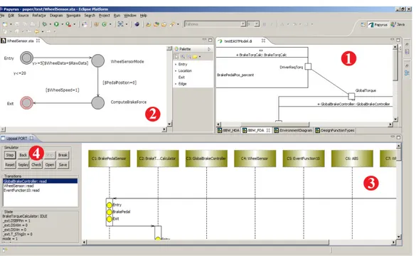
Figure 3. Integrated EAST-ADLPlatform Editor (1), Timed Automata Editor (2), UPPAALPORTSimulator (3), and the UPPAALPORTVerifier (4).
5.1.1. The EAST-ADLSystem Model
Using the EAST-ADLsystem and behavioral model, we describe how functional blocks are related to each other
in capturing behavior and algorithms of the system as well as the environment. In EAST-ADLsystem modeling,
func-tional blocks in FAA are built from interconnected fps with well-defined interfaces consisting of a set of input- and
output data ports. In the current work, the architectural specifications are used from structure, behavioral, and timing EAST-ADLpackages [4, 16] in order to simplify the definition of the semantics and the integration towards UPPAAL
PORT. The core ICM consists of the following modeling elements: composite Analysis Function Type, ba-sicAnalysis Function Prototype, connectors Function Connector, Flow Ports, Event Function, Event Function Flow Port associated to a set of ports, Periodic Constraint associated to anfp,Delay Constraint,
and a behavioral description namedBehavioral Model. All the elements, except the last, are translated from the EAST-ADLstructure package. The behavioral description complemented with timing formalisms complies with the
component-based approach that enables early formal analysis of relevant concerns. 5.1.2. Timed Behavior
The timed behavior of a functional block is defined as aTA, extended with data variables and a final location. An
fpis described by its interface in terms of ports and a timed behavior [7]. TheTAmodel is an abstraction of the fp
behavior and assumed properties. For analysis and verification of EAST-ADLFAA models in UPPAALPORT, each
fpis associated with a behavioral model consisting ofTA, and a mapping between ports and the TA variables. We
provide a mapping scheme between flow ports andTAvariables as additional model parameters. 5.2. Model transformation to UPPAALPORT
In this work, no ft can have instances of other ft with the exception of FAA. We have developed the model
transformation shown in Fig. 4. We specify the input models for UPPAALPORTas described in theICM. In order to simplify the semantic definition ofICM, we focus on the EAST-ADLlanguage constructs relevant for functional and
timing verification. For this reason, other modeling constructs, such as requirements models and variability models, are not addressed in this work.
EAST-ADL Profile +
MetaModel
EAST-ADL Model
conforms
conforms
Intermediate Analysis
Model
Intermediate Analysis
MetaModel
conf rms
conforms
M2M
transf rmation
M2M
transformation
UPPAAL PORT
input file
M2T
transformation
M2T
transformation
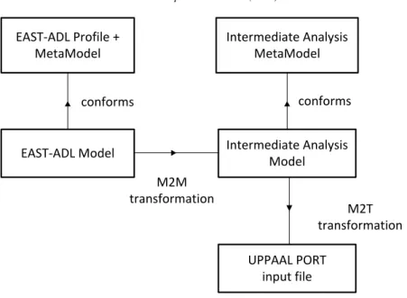
Figure 4. Model Export from EAST-ADLto UPPAALPORT.
5.2.1. ViTAL and ICM Integration
We define a structural integration inside the ViTAL tool, which consists of the formal definition of the constructs of the EAST-ADLlanguage. TheICMconsists of the following elements: composite ft, basic fp, connections, ports,
event functions, and timing constraints. Using these elements, we derive all constructs in the EAST-ADL system model. We consider that each modeling element, except for the FAA ft, has a set of flow ports, through which it
can interact.Flow Ports are associated by a set of EAST-ADLtypes namedEADataTypes, which are used for data
representation, e.g., integer with the specific rangeEAInteger. A Flow Port is associated with the same type of data as the associated variable.
Similar to the EAST-ADLlanguage,Function Connectors define how data can be transferred between two fps.
We assume there is no time consumption for data transmitted through a connector. This assumption is used when modeling the abstract functional system in EAST-ADLat analysis level, in which most implementation elements are
hidden. Other structural EAST-ADL constructs are not represented directly by any modeling element, hence they
do not influence the transformation. For the integration presented in ViTAL, the architectural information related to structure and timing are partially derived from the EAST-ADLmodel. Everyfpis annotated in theICMwith anEvent
Function that submits to a Periodic Constraint. An Event Function is a trigger generator annotated with a parameter T for period. A new period starts every T time units, and the event function generates a trigger after each period elapses.
The EAST-ADLmodel restricts thefpbehavior. For example, the read-execute-write semantics mentions that input
Flow Ports may only be accessed at the beginning of each triggering, and output Flow Ports are only written at the end of the computation. Therefore,TA( fp)defines its behavior augmented with an external ICM interface. The
interface of an fp consists ofFlow Ports and the triggering information. An input Flow Port has an associated
variable holding the current data value. A primitivefpcorresponds to a primitive ICMFunction Prototype with an
automaton that can capture the behavior of the associated ft. The internal computation of an fpstarts with reading all
inputFlow Ports. This internal input data is used together with other functional information during thefpexecution,
before writing the variables to the outputFlow Ports. With these assumptions in mind we can describe the ICM’s actual semantics.
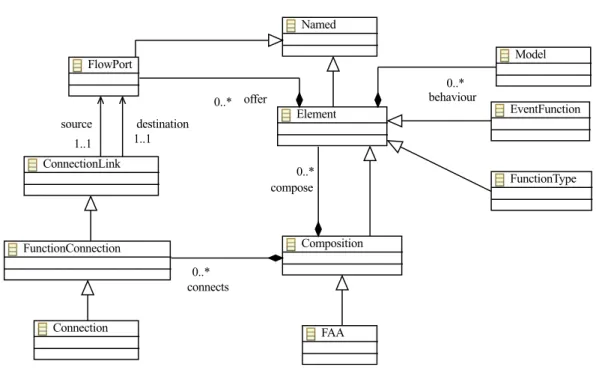
The modeling elements of the ICM, used in the integration, are described in Fig. 5 where the elements represent the structure information at analysis level of abstraction, model behavior, and timing information. TheICMprovides system modeling concepts which are mapped to concepts of component based design.Element can be mapped with aFunctionType and EventFunction elements. There are connectors such as FunctionConnection and ports
Figure 5. Simplified diagram representing the meta-model elements of the ICM.
such asFlowPort. A FlowPort is of type Analysis Data Type. Furthermore an Element can have a behavioral description as aModel element. Every FlowPort can be provided with an associated EventFunctionFlowPort, which is used together with theDelayConstraint.
The ICM obtained after the transformation represents the TA behaviors with triggering and timing information and some assumed functionality. ViTAL is used in this case to provide an extension to the internal behavior of fpnot
only in terms of timing, but also functionality. 5.2.2. Implemented Model Transformation
The EAST-ADL language is implemented as a UML2 profile that provides the ability to describe EAST-ADL
-compliant models using this profile. The Papyrus UML tool implements the stereotypes as defined in EAST-ADL
specification. ViTAL is based on Eclipse3, which ensures an integration with the UML Editor in Papyrus, needed
for developing EAST-ADL models. The EAST-ADL editor plugin uses Papyrus UML to create the actual EAST -ADLsystem model. Papyrus saves its models in two files, one using a “.uml" extension and the other using a “.di"
extension. The former file contains the actual model information, whereas the latter file contains all the graphical information. The VITAL tool provides an intuitive and user friendly graphical environment based on a popular development platform named Eclipse. Our transformation and verification tool is built upon an MDD set of Eclipse plug-ins: Eclipse Modeling Framework4, Graphical Modeling Framework, Graphical Editing Framework, ATLAS
Transformation Language (ATL), and Acceleo. Fig. 7 shows the EAST-ADLmodel transformation.
The Papyrus UML Editor generates EAST-ADLmodels, which are used for our mapping to UPPAALPORT. As shown in Fig. 4, we introduce anICM as the interface between the EAST-ADL model and UPPAAL PORT input model. The intermediate model conforms to the EAST-ADLmetamodel that is aligned with the EAST-ADLprofile and UML metamodel. The structural transformation maps an EAST-ADLmodel, which was created in the Papyrus UML
modeling environment, intoICM. The Model to Model transformation is shown in Fig. 4. The structure of theICMis
3Eclipse is a software development environment with an extensible plug-in system.
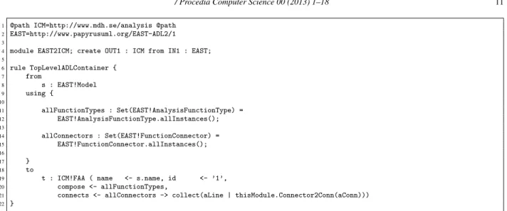
1 @path ICM=http://www.mdh.se/analysis @path 2 EAST=http://www.papyrusuml.org/EAST-ADL2/1 3
4 module EAST2ICM; create OUT1 : ICM from IN1 : EAST; 5 6 rule TopLevelADLContainer { 7 from 8 s : EAST!Model 9 using { 10 11 allFunctionTypes : Set(EAST!AnalysisFunctionType) = 12 EAST!AnalysisFunctionType.allInstances(); 13 14 allConnectors : Set(EAST!FunctionConnector) = 15 EAST!FunctionConnector.allInstances(); 16 17 } 18 to
19 t : ICM!FAA ( name <- s.name, id <- ’1’, 20 compose <- allFunctionTypes,
21 connects <- allConnectors -> collect(aLine | thisModule.Connector2Conn(aConn))) 22 }
Figure 6. ICM Transformation rules for the associated elements.
the basis of the Model to Text transformation needed for the integration of the UPPAALPORTinput model5. This step
of the transformation achieves an integration between the modeling domain of EAST-ADLand that of UPPAALPORT.
We use the ATL Model to Model Component due to its simplicity and integration within the Eclipse platform. We have implemented the mapping rules presented in Section 5.2.1 as an ATL description of the transformation logic. For the transformation, a few modifications of both metamodels have been made. In principle, these changes are in fact ways to preserve the semantics of the original model. For instance, EAST-ADLuses the type - prototype constructions
in which the declaration is in ft, and the actual usage is infp. In this case, the structural transformation has a pointer
betweenftand the containedTA( fp).
Intermediate Model Transformation: This step of the integration is based on the ATL model transformation lan-guage [18], which is composed of the following elements: a header section that defines the name of the transformation module and the variables corresponding to the intermediate and EAST-ADLmodels, a set of helpers, and a set of rules that defines the way intermediate models are generated from the EAST-ADLones. Based on these attributes introduced for model transformation, we have defined some rules of transformation. The M2M transformation depicted in Fig. 4 is described for the top level rule of the transformation in Fig. 6. We defined the M2M transformation within an EAST2ICM Module (line 4). It operates on a non-empty source model EAST producing a non-empty target model ICM (line 5). TheEAST2ICM has a number of associated ModuleElements which are either Rules or Helpers (lines 7-23). TheFlowPort Helper is used as a query function in the context of the EAST2ICM Module itself for matching theEAST Connection’s explicit flow direction. We provide these transformation Rules to produce target elements such asTopLevelADLContainer (line 7), including the inports and outports.
In addition to the structural integration, the behavioralTA transformation needs to be carried out. In order to model the timing and behavior of an fp, we use aTAeditor. The behavior can be represented in a graphical editor by
the developer. These models are different from UPPAALTA models as follows: (i) the timed behavior is extended with a final location out of which no edges are leaving, and (ii) synchronization channels are not allowed, because of the semantics used byICMmodels. For more details on the specifics of theTAemployed by UPPAALPORT, we refer the reader to the work in [7]. We mapTA variables to the flow ports of the EAST-ADLfunctions. We provide a variable to the port mapping plug-in. In the current version of ViTAL, the mapping uses the name of the TA file to automatically generate the parameters to be used.
Once the aforementioned steps have been completed, theTAandICMcan be merged into an XML-format accepted by the UPPAAL PORTtool6. This transformation is carried out using the Acceleo code generator to transform the
5We refer the reader to the UPPAALPORTinput language reference manual for further details [17]
Eclipse IDE
EAST-ADL editor plugin
(architecture modeling)
Timed Automata editor plug-in
(timing/behavior modeling)
Mapping Editor plug-in
UPPAAL PORT plug-in
UPPAAL PORT server
command
response
Figure 7. Overview of the ViTAL tool architecture.
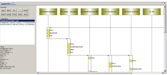
Figure 8. Simulator View in the ViTAL tool chain.
ICMinto code. The ViTAL tool architecture is shown in Fig 7. The user interface contains an editor for EAST-ADL
models in the Eclipse framework, as well as aTAeditor to model the behavior of EAST-ADLsystem models. UPPAAL
PORTintroduces support for simulation and verification, using a client-server architecture [19]. The UPPAALPORT
model-checker consists of two modules: the Eclipse plug-in used as the graphical simulator and the server executing the verification.
The simulator is used to validate the behavior and timing of an EAST-ADLmodel. The simulator allows stepping forward and backwards in the state space, while selecting possible transitions, as described in Fig. 8. In a trace, a data transfer is defined by the exchange of data between EAST-ADLfps(annotated with the timed automata locations)
via their respective ports. Also, by using the verifier , it is possible to establish, by model checking the described TA behavior, whether the EAST-ADLsystem model satisfies the functional or timing properties, as specified by the
requirements engineer in EAST-ADLlanguage.
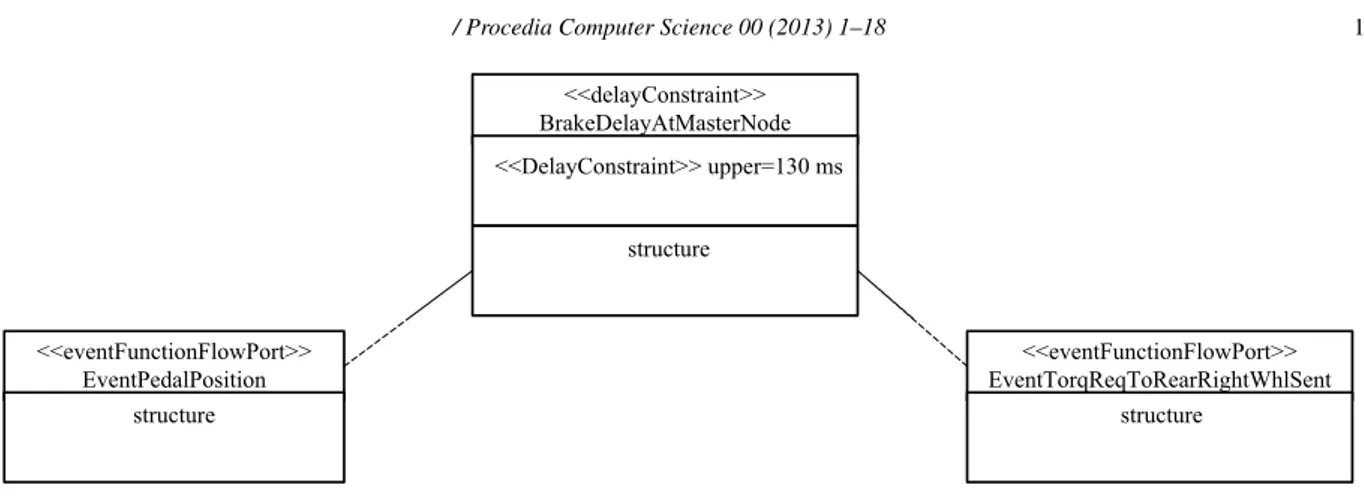
<<eventFunctionFlowPort>> EventPedalPosition structure <<delayConstraint>> BrakeDelayAtMasterNode structure <<DelayConstraint>> upper=130 ms <<eventFunctionFlowPort>> EventTorqReqToRearRightWhlSent structure
Figure 9. Associated timing constraints specified in the EAST-ADLModels.
5.2.3. Automatic verification of timing constraints
One of the key issues in the context of automotive software systems is verifying timing requirements on the bus or the ECU timing properties in EAST-ADL at Analysis and Design Level. These timing properties are
spec-ified in the EAST-ADL language in the structure package asdelayConstraint. This artifact is attached to two
eventFunctionFlowPorts that are used to constrain two Flow Port artifacts and defines bounds on system timing attributes.
ThedelayConstraint requires a delay between a set of input Flow Ports and a set of output Flow Ports. To illustrate, we use a simplified example of a timing constraint associated to an EAST-ADLsystem model, as depicted in
Fig. 9. This structure specification can be used in the M2M transformation and in the intermediate model to validate existing realizations of the system.
We have augmented the intermediate metamodel with thedelayConstraint structural information, which should also include the associatedFlow Ports. With ViTAL, we may go a step further towards automatic verification of delay constraints. Starting with the delay constraints information contained in the EAST-ADL model, we build a
refined model of the intermediate model. Refining a constraint may consist in fixing parameters values, in accordance with the initial specification. Then, ViTAL simulates the refined model, revealing possible inconsistencies in the specification, by using the UPPAALPORTverification engine.
6. Case Study: Brake-by-Wire Control System
We check the applicability of our approach on the Brake-By-Wire (BBW) system, modeled in EAST-ADL. Fig.
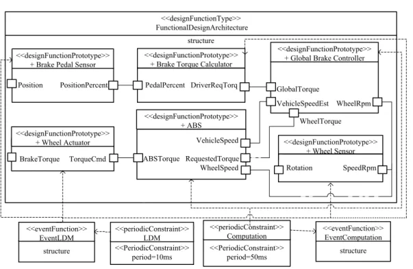
10 depicts a simplified schematic illustration of the BBW with Anti-lock Braking System (ABS) function. The system reads the pedal position percentage used to compute the desired torque and calculates the torque required for each wheel. The wheel sensor measures the wheel speed for the controller and theABScontrols braking to prevent locking of the wheel based on the slip rate.
6.1. BBW System Model and Functionality
The functionality of the system can be divided between sensors and actuators fps, and computations fps. The
Brake Pedal Sensor (BPS) transforms the raw data (the voltage that is related to the pedal angle) into a percentage of a maximum value of the brake force. In the case of theWheel Sensor (WS), the raw data corresponds to the actual wheel speed. TheWheel Actuator (WA) is modeled as an fp, which computes the brake force. The computation is
divided between twofps: theBrake Torque Calculator (BTC) computes the requested brake force, which is used
as input in theGlobal Brake Controller (GBC) that calculates a basic brake force on each of the wheels. The basic brake force may be adjusted depending on the difference between the estimated vehicle speed and the respective wheel speed.
The system is composed of five Electronic Control Units (ECU) connected by a network bus. The central ECU has three components: theBPSthat reads the position of the pedal percentage, theBTC that computes the desired
<<desi n u c ion y e>> Fu c ion l esignArchitect re <<designFunctionType>> FunctionalDesignArchitecture
< d signF nctio Pr t ty e>> Glo a Br k Co t oller <<designFunctionPrototype>> GlobalBrakeController Wheel_r m Wheel_rpm Whee _t r ue Wheel_torque
< d signF nctio Pr t ty e>> Glo a Br k Co t oller <<designFunctionPrototype>> GlobalBrakeController Wheel_r m Wheel_rpm Whee _t r ue Wheel_torque st uct re structure < F nct onConnec or > <<FunctionConnector>> <<designFunctionType>> FunctionalDesignArchitecture structure PedalPercent DriverReqTorq Position PositionPercent <<designFunctionPrototype>> + Brake Pedal Sensor
<<designFunctionPrototype>> + Brake Torque Calculator
WheelTorque structure <<eventFunction>> EventLDM <<PeriodicConstraint>> period=10ms <<periodicConstraint>> LDM structure <<eventFunction>> EventComputation <<PeriodicConstraint>> period=50ms <<periodicConstraint>> Computation GlobalTorque VehicleSpeedEst WheelRpm <<designFunctionPrototype>> + Global Brake Controller
BrakeTorque TorqueCmd <<designFunctionPrototype>>
+ Wheel Actuator VehicleSpeed
ABSTorque RequestedTorque WheelSpeed <<designFunctionPrototype>> + ABS Rotation SpeedRpm <<designFunctionPrototype>> + Wheel Sensor
Figure 10. Brake by Wire control system.
global torque, andGBCthat calculates the torque required for each wheel. The other four ECUs are connected to the four wheels, respectively. At each wheel, theWSmeasures the wheel speed and sends a signal to theGBCcomponent. TheABScontrols the wheel braking in order to prevent locking of the wheel, based on the slip value. The slip value is calculated by the equation:
slipRate = (vehicleSpeed wheelSpeed ⇥ r)/vehicleSpeed,
where vehicleSpeed is the estimated vehicle speed value, wheelSpeed the wheel speed sensor value, and r the wheel radius. The friction coefficient of the wheel has a nonlinear relationship with slipRate: when slipRate increases from zero, the friction coefficient also increases and the value reaches the peak when slipRate is around 0.2. After that, further increase in slipRate reduces the friction coefficient. For this reason, if slipRate is greater than 0.2 the brake actuator is released and no brake is applied, or else the requested brake torque is used. The system has been modeled in Papyrus UML Editor, where a UML profile is used for architectural description. We have modeled, simulated, and verified the BBW in our tool ViTAL, where we use only the structural and timing specifications. The architecture of the system is encapsulated in one FAA ftthat contains six interconnected fps modeled using theTAeditor. Each
TA( fp)defines the actual functional and timing behavior of the fp.
The slip rate calculation is controlled by variableslipRate. For instance, from location calculateSlipRate, based on the current vehicle speedvSpeed, the wheel speed wSpeed, and the wheel radius wRadius, the TorqueCmd controls the wheel braking in order to prevent locking of the wheel. Consequently, theABSenters locationTorque and jumps back to locationStart, provided that slipRate is greater than 0.2, the brake actuator is released and no brake is applied, or else the requested brake torque is used.
6.2. Analysis and Verification
Different types of analysis can be used for functional and timing constraints in EAST-ADL. We demonstrate the new methodology through the BBW using the ViTAL tool. Requirements on the system design are expressed as
TCTL statements and can be verified by UPPAALPORT. A list of requirements and the verification conditions are
given below as a set of properties concerning the safety and liveness of the BBW. We discuss a few representative properties. The property of deadlock freedom is satisfied for all execution paths of the state-space.
Timing Verification: Our approach and the underlying tool support for verification of architectural properties sup-ports the specification of timing properties in TCTL specification. As an example of such a property, which ensures the brake reaction delay specified in the BBW model, the following specification was verified:
A[ ](BBW.reaction imply (BBW.clock < 200))
We note that ViTAL automatically uses the delay constraints information from EAST-ADL models during
veri-fication. To handle automated integration during verification ofTCTLproperties of this type, this delay constraint information is considered a transformation parameter and then checked automatically in UPPAAL PORT. In order
to verify bounded response time properties for the brake reaction delay, we use an observerBBW fp with a certain
syntactical manipulation on the system model. TheBBW’s input reaction from theBPS fpand its output reaction from
theWA fpare modeled by the associated flow ports. This controllable model has no impact on the actual behavior of
the system, but it interacts with the associatedfpto model the bounded response time. Similarly, in cases when other
DelayConstraint requirements are specified, the interactions between the observer model and the constrainedfps
are updated in order to cope with the modified EAST-ADLtiming information.
Functional Verification: One of the functional requirements of the system is related to the slip rate s. With ViTAL, we can verify the following functionality: in case the slip rate variable exceeds 0.2, the brake actuator is released and no brake is applied:
A[ ](BTC.slipRate > 0.2 imply (ABS.brake == 0))
Other properties (Lead-to properties1) related to functional and timing requirements are verified and listed below:
• Based on the internal behavior every time the system runs it will eventually execute theABSmode which trig-gers the calculation of the brake force when the brake pedal is activated:
(BPS.BrakePedal) ! (GBC.mode == ABS ^ GBC.BrakeForce)
• Based on the values of ports, if the brake pedal is activated then the value of its position should be received by theGBC fp:
(BPS.BrakePedal) ! (GBC.BrakeCtr ^ GBC.in == 1)
Model-checking the properties requires an average of around 1.2 seconds per verified property (on an 2.4 GHz Intel Core i5).
7. Related Work
Several works on the formal analysis and verification of Architecture Analysis and Design Languages (AADLs), the main basis for behavioral verification of real-time embedded systems, have been carried out [20, 21, 22, 23]: An external behavior specification is used and verified by communicating TA [20] or source code [21]. To construct an
analyzable behavioral and architectural model,AADL enriched with its behavioral annex [22, 23] is considered the underlying model used for the verification. Berthomieu et al. [22] useAADLand its behavior annex into the Fiacre language towards behavioral verification with TINA tool. The main difference in our work is that we give a graphical behavior specification with support for model checking, system simulation, timing analysis, and an integrated tool based on Eclipse.
For safety-driven system development in the automotive domain, feature based analysis is prescribed by ISO standard as the state-of-the art approach to functional safety. However, at an early stage it is difficult to see function dependencies that would result in updated function requirements. A. Sandberg et al. [24] provide an approach that performs iterative analysis for managing changes in the safety architecture at analysis level and still meets function specific safety goals derived at vehicle level. In comparison to our work, their main concern is to define the semantics for requirement selection in order to ensure correct inclusion of requirements for a function definition. There is no formal modeling approach to the behavioral definition of the language.
Several methods have been developed for the formal analysis and verification of EAST-ADLmodels: F. Nallet et
al. [25] describe the use of UML Profile for Modeling and Analysis of Real-Time and Embedded systems (MARTE) [26] together with EAST-ADLfor timing analysis [25]. In the context of EAST-ADLUML2 profile, Feng et al. [27]
propose a translation of an existing behavioral principle of the system specified in activity diagrams into PROMELA and use the SPIN model checker for formal verification of EAST-ADLfunctional models. In contrast to our work, the
integration of timing constraints in the behavioral model is not allowed and formal analysis on the real-time properties of the behavior model is not considered at all. Qureshi et al. [28] describe an integration effort towards formal veri-fication of EAST-ADLmodels based on timing constraints, i.e., the EAST-ADLmodels are manually transformed into UPPAALmodels that are then validated in terms of the timing- and triggering constraints. Despite their approach offer-ing prototype support for model-checkoffer-ing reachability and safety properties correspondoffer-ing to the timoffer-ing constraints, it is limited in terms of model checking functional constraints and complex systems with respect to state space and time. The ViTAL tool, on the other hand, has this capability via the PORT model-checking technique. Refer to [7] for further information on the advantages of using a PORT technique.
In our previous work [10, 29] an integration effort towards formal modeling and analysis of EAST-ADLmodels
based on timing constraints was investigated where the models were manually translated into TA formats in UPPAAL
series tools [30]: Kang et al. [10] performed an earlier study towards verification of EAST-ADLmodels using UPPAAL
PORTwith the aim of identifying integration needs and the results were used as the basis of our approach in the current
work. Furthermore, recent additions to EAST-ADL were considered in [29], including both timing and behavioral
extensions in compositional and refinement reasoning and eliminated the need for intermediate formalism such as ICM and performed direct transformation of EAST-ADLspecifications to an extended UPPAALTIGAECDAR[30].
Nevertheless, these early works did not support transformation in full automation, and in comparison to our current work, no implementation was available.
8. Conclusion and Future Work
In this work, we present the use of formal modeling and verification techniques at an early development stage of safety-critical automotive products which are originally described in the EAST-ADLarchitectural language. We employ the formalism of TA to facilitate the capture of the execution flow inside each functional block and the complex interactions between components mainly at Analysis level. We verify these constraints by using the UPPAAL
PORTmodel checker.
The modeling and verification tool ViTAL provides an unambiguous behavioral description of EAST-ADLmodels,
and brings formal verification capabilities to the EAST-ADLmodels. ViTAL enhances the behavioral definition of the
EAST-ADLlanguage and allows formal modeling, simulation, and verification of functional and timing requirements.
With ViTAL, we have integrated such models, in order to be able to simulate and check whether a given requirement is satisfied, by model-checking theTAdescription with UPPAALPORT. The independence introduced by the
“run-to-completion" semantics, employed by the EAST-ADLfunctional modeling, is exploited by UPPAALPORT, in order
to reduce time and space requirements for model checking. Our technique improves behavior modeling, verification and analysis capability of EAST-ADL, and the result shows the applicability of model checking in safety-critical
As future work, our research targets are: (i) richer transformation constructs to validate delay and synchronization constraints in fully automatic, (ii) the seamless integration of UML behavioral diagrams in particular activity dia-grams or state machines as a specification formalism into ViTAL (to specify real-timing constraints on the UML level, we have investigated and defined an extended UML profile which integrates relevant concepts from EAST-ADLand
MARTE profiles [31, 32]), and (iii) more elaborate verification of non-functional properties and more refined config-urations of the generated model. For example, minimizing the use of certain resources, such as CPU, energy, memory, etc, while preserving functional correctness, timing requirements and other resource constraints. Our recent effort on modeling formal energy-aware real-time (ERT) behaviors in EAST-ADLhas been initiated and an extended UML profile augmenting EAST-ADLand MARTE is presented to facilitate those behaviors by means of state machines [31].
Acknowledgments
This work was funded by FNRS (Fonds de la Recherche Scientifique) and TPA project in Belgium, ARTEMIS Joint Undertaking under grant agreement number 269335, from VINNOVA, the Swedish Governmental Agency for Innovation Systems, and Swedish Research Council, within the MBAT and ATAC projects. Special thanks to Hen-rik Lönn, Thomas Söderqvist, Daniel Karlsson from Volvo Technology and Lei Feng from KTH Royal Institute of Technology for their valuable feedback.
References
[1] M. Broy, Challenges in Automotive Software Engineering, in: Proceedings of the 28th international conference on Software Engineering, 2006, pp. 33–42.
[2] C. MAENAD, EAST-ADL Domain Model Specification, intermediate version Edition, http://www.maenad.eu/, 2011, pp. 2–143.
[3] P. Cuenot, P. Frey, R. Johansson, H. Lönn, Y. Papadopoulos, M.-O. Reiser, A. Sandberg, D. Servat, R. Tavakoli Kolagari, M. Törngren, M. We-ber, The EAST-ADL Architecture Description Language for Automotive Embedded Software, in: Model-Based Engineering of Embedded Real-Time Systems, Lecture Notes in Computer Science, Springer, 2011, pp. 297–307.
[4] T. A. ATESST2 Consortium, EAST-ADL Profile Specification, 2.1 RC3 (Release Candidate), 2nd Edition, www.atesst.org, 2010, pp. 10–75. [5] J. Rumbaugh, I. Jacobson, United Modeling Language User Guide, 2nd Edition, Addison-Wesley, 1998.
[6] P. Cuenot, S. Gerard, H. Lonn, M. Reiser, D. Servat, C. Sjostedt, R. Kolagari, M. Torngren, M. Weber, et al., Managing Complexity of Automotive Electronics using the EAST-ADL, in: 12th IEEE International Conference on Engineering Complex Computer Systems, 2007, pp. 353–358.
[7] J. Håkansson, P. Pettersson, Partial Order Reduction for Verification of Real-time Components, in: Proceedings of the 5th International Conference on Formal Modeling and Analysis of Timed systems, Springer-Verlag, 2007, pp. 211–226.
[8] E. Enoiu, R. Marinescu, C. Seceleanu, P. Pettersson, ViTAL: A Verification Tool for EAST-ADL Models Using UPPAAL PORT, in: 17th International Conference on Engineering of Complex Computer Systems, IEEE, 2012, pp. 328–337.
[9] R. Alur, D. L. Dill, A Theory of Timed Automata, in: Theoretical Computer Science, Vol. 126, 1994, pp. 183 – 235.
[10] E.-Y. Kang, P. Y. Schobbens, P. Pettersson, Verifying Functional Behaviors of Automotive Products in EAST-ADL2 using UPPAAL-PORT, in: Proceedings of the 30th International Conference on Computer Safety, Reliability and Security, Springer-Verlag, 2011.
[11] J. Bengtsson, B. Jonsson, J. Lilius, W. Yi, Partial Order Reductions for Timed Systems, in: Lecture Notes in Computer Science: Concurrency Theory, Vol. 1466, Springer Berlin / Heidelberg, 1998, pp. 485–500.
[12] P. Godefroid, P. Wolper, Using Partial Orders for the Efficient Verification of Deadlock Freedom and Safety Properties, in: Lecture Notes in Computer Science: Computer Aided Verification, Springer Berlin / Heidelberg, 1992, pp. 332–342.
[13] J. Carlson, J. Håkansson, P. Pettersson, SaveCCM: An Analysable Component Model for Real-Time Systems, in: Proceedings of the 2nd Workshop on Formal Aspects of Components Software, Vol. 160, Elsevier, 2006, pp. 127–140.
[14] C. ARTEMIS MBAT, Consortium Public Deliverables (Nov. 2013). URLwww.mbat-artemis.eu/
[15] J. Suryadevara, E.-Y. Kang, C. Seceleanu, P. Pettersson, Bridging the Semantic Gap between Abstract Models of Embedded Systems, in: 13th International Symposium on Component Based Software Engineering, Springer, 2010.
[16] T. A. ATESST2 Consortium, Evaluation Report EAST-ADL2 Behavior Support, D2.1 Appendix A3.4, d2.1 appendix a3.4 Edition, www.atesst.org, 2010.
[17] M. Åkerholm, J. Carlson, J. Håkansson, H. Hansson, M. Nolin, T. Nolte, P. Pettersson, The SaveCCM Language Reference Manual, Technical Report MDH-MRTC-207/2007-1-SE, Målardalen University (January 2007).
[18] F. Jouault, I. Kurtev, Transforming Models with ATL, in: Satellite Events at the MoDELS 2005 Conference, Springer, 2006, pp. 128–138. [19] J. Håkansson, J. Carlson, A. Monot, P. Pettersson, Component-Based Design and Analysis of Embedded Systems with UPPAAL PORT, in:
6th International Symposium on Automated Technology for Verification and Analysis, Springer-Verlag, 2008, pp. 252–257.
[20] T. Abdoul, J. Champeau, P. Dhaussy, P.-Y. Pillain, J.-C. Roger, AADL Execution Semantics Transformation for Formal Verification, in: 13th IEEE International Conference on Engineering of Complex Computer Systems, 2008, pp. 263 –268.
[21] J. Hugues, B. Zalila, L. Pautet, F. Kordon, From the Prototype to the Final Embedded System using the Ocarina AADL Tool Suite, in: Transactions in Embedded Computing Systems, Vol. 7, ACM, 2008, pp. 1–42.
[22] B. Berthomieu, J.-P. Bodeveix, S. Dal Zilio, P. Dissaux, M. Filali, S. Heim, P. Gaufillet, F. Vernadat, Formal Verification of AADL models with FIACRE and TINA, in: 5th International Congress and Exhibition on Embedded Real-Time Software and Systems, 2010.
[23] S. Björnander, C. Seceleanu, K. Lundqvist, P. Pettersson, ABV Verifier for the Architecture Analysis and Design Language (AADL), in: International Workshop on UML and AADL, 2011.
[24] A. Sandberg, D. Chen, H. Lönn, R. Johansson, L. Feng, M. Törngren, S. Torchiaro, R. Tavakoli-Kolagari, A. Abele, Model-based Safety Engineering of Interdependent Functions in Automotive Vehicles using EAST-ADL2, in: Proceedings of the 29th International Conference on Computer Safety, Reliability, and Security, Springer-Verlag, 2010, pp. 332–346.
[25] F. Mallet, M.-A. Peraldi-Frati, C. Andre, Marte CCSL to Execute East-ADL Timing Requirements, in: IEEE International Symposium on Object/Component/Service-Oriented Real-Time Distributed Computing, 2009, pp. 249 –253.
[26] C. André, F. Mallet, R. De Simone, Modeling of Immediate vs. Delayed Data Communications: from AADL to UML MARTE, in: The Forum on specification & Design Languages, ECSI, 2007, pp. 249–254.
[27] L. Feng, D. Chen, H. Lönn, M. Torngren, Verifying System Behaviors in EAST-ADL2 with the SPIN Model Checker, in: International Conference on Mechatronics and Automation, 2010, pp. 144 –149.
[28] T. Naseer Qureshi, D. Chen, M. Persson, M. Törngren, Towards the Integration of UPPAAL for Formal Verification of EAST-ADL Timing Constraint Specification, in: The International Workshop on Model-Based Design with a Focus on Extra-Functional Properties, 2011. [29] E.-Y. Kang, P.-Y. Schobbens, A. Legay, Verification of component-based architectural models on autonomous truck systems, in: Proceedings
of the 9th International Conference and Workshops on the Engineering of Autonomic and Autonomous Systems, IEEE Computer Society, 2011.
[30] ECDAR: Environment for Compositional Design and Analysis of Real-time systems, http://ecdar.cs.aau.dk/ (2010).
[31] E.-Y. Kang, G. Perrouin, P.-Y. Schobbens, Towards Formal Energy and Time Aware Behaviors in EAST-ADL: An MDE Approach, in: Proceedings of the 12th International Conference on Quality Software, IEEE Computer Society, 2012.
[32] E.-Y. Kang, G. Perrouin, P.-Y. Schobbens, XFG language and its profile for modeling and analysis of energy-aware and real-timed behaviors, in: Technical Report, 2012.