Enhanced Automotive Real-Time Testing
Through Increased Development Process
Quality
Johan Holmqvist and Tord Karlsson
School of Innovation, Design and Engineering
M¨
alardalen University
Sweden
School of Innovation, Design and Engineering
Master Thesis in Computer Science
Date:
2010-06-10 Title:
Enhanced Automotive Real-Time Testing Through Increased Development Process Quality
Authors:
Johan Holmqvist Tord Karlsson Supervisors:
Prof. Paul Pettersson, M¨alardalen University Charlotta Sigrand, Scania
Examiner:
Abstract
The purpose of this master thesis is to improve the quality of software testing in a large company developing real-time embedded systems. Software testing is a very important part of software development. By performing comprehensive software testing the quality and validity of a software system can be assured. One of the main issues with software testing is to be sure that the tests are correct. Knowing what to test, but also how to perform testing, is of utmost importance.
In this thesis, we explore different ways to increase the quality of real-time testing by introducing new techniques in several stages of the software develop-ment model. Four compledevelop-mentary methods are suggested. The proposed meth-ods are validated by implementing them in an existing and completed project on a subset of the software development process. The original output from the completed project is compared with the new output.
The presented results from the validation are positive in the sense that it is shown that the test stage was more qualitative, mostly due to a higher level of quality on input from earlier stages.
Preface
This thesis has been the academic version of a roller coaster, changing direction and speed at almost every turn. In a way it is the perfect end to an otherwise rock-steady education. We are grateful to the people at Scania who gave their insight and expertise – especially our supervisor Charlotta Sigrand and the rest of her testing team, REVT, who welcomed us into their group. We also want to thank Jonny who always took his time to give us feedback regarding our ideas. We are not to forget our supervisor at M¨alardalen University, prof. Paul Pettersson, who provided us with expert advises and guidance when needed. Last and possibly least, we would not have gotten far during the long cold winter without Arvid Nordquist and his fine brand of coffee.
Johan Holmqvist, Tord Karlsson V¨aster˚as, June, 2010
Contents
1 Introduction 1 1.1 Background . . . 1 1.2 Goals . . . 1 1.2.1 Original Goals . . . 1 1.2.2 Updated Goals . . . 2 1.3 Limitations . . . 2 1.4 Validation . . . 3 1.5 Related Work . . . 3 1.6 Thesis Outline . . . 3 2 Software Testing 4 2.1 Static and Dynamic Testing . . . 42.1.1 Dynamic Testing . . . 4
2.1.2 Static Testing . . . 4
2.2 Test Design Methods . . . 5
2.2.1 Black-Box Testing . . . 5 2.2.2 White-Box Testing . . . 6 2.3 Test Levels . . . 6 2.3.1 Unit Testing . . . 6 2.3.2 Integration Testing . . . 6 2.3.3 System Testing . . . 6 2.3.4 Acceptance Testing . . . 7
2.4 Testing of Real-Time Systems . . . 7
2.5 Automated Testing . . . 7
2.5.1 Test Execution Automation . . . 8
2.5.2 Automatically Derived Tests . . . 8
3 Software Development Models 10 3.1 Development Process . . . 10
3.2 Development Models . . . 11
3.2.1 Waterfall Process Model . . . 11
3.2.2 Prototyping Process Model . . . 13
3.2.3 Spiral Process Model . . . 13
3.2.4 Iterative Enhancement Model . . . 14
3.2.5 V-model . . . 14
3.2.6 Extreme Programming . . . 15
3.2.7 Other Process Models . . . 16
CONTENTS
4 Formal Specifications 18
4.1 Requirements . . . 18
4.2 Specifications . . . 18
4.3 Different Ways to Formal Specifications . . . 19
4.3.1 Mathematical Logic . . . 20
4.3.2 Z . . . 20
4.3.3 Unified Markup Language . . . 22
4.3.4 Message Sequence Chart . . . 22
4.3.5 Live Sequence Charts . . . 22
5 Document Version Control 25 5.1 How it Works . . . 25
5.1.1 Parallel Development . . . 26
5.2 Simulink Models . . . 28
5.2.1 The Model File Format . . . 28
5.3 Revisioning Model Files . . . 29
5.3.1 Document/File Dependencies . . . 29
6 Proposed Improvements 30 6.1 Document Inconsistency . . . 30
6.1.1 Method Description . . . 31
6.1.2 Method Results . . . 34
6.2 Simulink Models - Parallel Development . . . 34
6.2.1 Method Description . . . 34
6.2.2 Method Results . . . 35
6.3 Managing Process Information . . . 37
6.3.1 Method Description . . . 39 6.3.2 Method Results . . . 39 6.4 Formal Specifications . . . 39 6.4.1 Method Description . . . 40 6.4.2 Method Results . . . 40 6.5 Testing . . . 40
7 Conclusion and Future Work 42 7.1 Document Inconsistency . . . 42
7.2 Simulink Models - Parallel Development . . . 43
7.3 Managing Process Information . . . 43
7.4 Formal Specifications . . . 44
A Survey results 48 A.1 Risker med Model Based Development . . . 48
Chapter 1
Introduction
1.1
Background
This is a master thesis in computer science carried out on the behalf of Scania. Scania develop software using model based design. This is still a relatively new technique at Scania and therefore doubts exist regarding the quality of the software testing associated with the software developed using model based design.
Software testing is a very important part of software development and if the testing results are not reliable, the validity of the software cannot be either.
1.2
Goals
The objective is to review an existing software development process for a real-time system and to find room for certain improvements. The main goal is to improve the quality of real-time testing in the testing phase of the software development process.
To ease the work of identifying sections of the software development process that would benefit most from improvement measures a survey will be conducted. The survey will target persons with different roles and responsibilities in the development process.
The identified problems will be analyzed and improvement suggestions will be presented. These improvement suggestions will be validated by applying them to the development process of previously developed software.
1.2.1
Original Goals
The original general goal of this thesis was to propose a test strategy to use on software developed using model based design and automatically generated code. The following areas were to be researched:
• Which test levels are needed when using model based design? • What must be tested at respective level?
1.3. LIMITATIONS
• Which tools are needed? • Which roles are involved?
• Define the connections between requirements, design and testing. • Required test coverage?
• The resulting strategy should be applied to an existing function.
1.2.2
Updated Goals
To get a clearer view of the problem at hand, a survey was carried out at Scania as a first step. A number of handpicked employees at key positions, within model based development, throughout the organization were interviewed. The goal was, more specific, to identify and determine the greatest risks with model based development according to the software developers at Scania. The survey results, presented in Appendix A, indicated that the developers were not worried over the fact that most of the code they worked with is generated from models. Nor did the results show that any specific concern regarding model based development versus more traditional methods existed.
The survey did, however, reveal room for further improvements in other areas within the software development process. Due to this fact, the area of this thesis differs a bit from what was originally intended.
When the results from the survey had been analyzed, a new set of goals for this thesis were established.
The results implied that most of the problems associated with testing did not originate from the test case creation itself, but rather from earlier stages of the software development process. Several of the experienced problems were due to outdated documentation – which could, for example, be the product of undocumented signal changes.
The strategy of the new direction of the thesis is to increase the quality of real-time testing by introducing a set of quality increasing measures in the software development process.
• What can be done to make the software specifications more precise? • How could the problem with models and revision control be solved? • Investigate the possibility to perform real-time tests.
• Which tools and roles are needed?
• The resulting strategy improving measures should be applied to an existing function.
1.3
Limitations
This thesis is limited to the software development, and software testing, de-partment of Scania and the emphasis is not on the proper academically correct solutions but on industrial terms. The validation work will be conducted at one of the software testing departments at Scania using their test rig on ECU (Electronic Control Unit) level.
1.4. VALIDATION
Due to technical reasons document structure and revision control will merely mimic the current method used with a couple of modifications.
1.4
Validation
The modified strategy will be tested on an existing, functional, piece of software. Some parts of the development process will not be fully carried out during the validation process. These parts will be replaced with, previously made, real data from the actual implementation of this function. The new output, generated during the validation process, will be compared against the output from the actual implementation. The results will be evaluated.
1.5
Related Work
Due to the nature of this thesis it is not possible to write about works directly related to the entire thesis, writing related works to each part would not be related to the goals. Therefore this section lists other works which try to im-prove software engineering in the automotive industry. Software engineering in the automotive industry is a hot topic for several reasons; one of them is the earlier lack of software engineers in the automotive industries. The amount of software in vehicles has increased rapidly [1]. The evolution of automotive engineering has brought several large topics to the automotive table [2]. Some of these are model driven development [3], test driven development, require-ments engineering [4], automatic testing, real-time and model based testing [5]. Given the complexity of the amount of distributed systems in automotive sys-tems and the communication between these it shares lots of properties with the telecommunication industry.
Most of the subjects will have to be visited in order to find out which ones actually can benefit the automotive engineering workplace today.
1.6
Thesis Outline
Chapter 1 - An introduction to the topic including problem definition and related works.
Chapter 2 - Theory on software testing.
Chapter 3 - Theory on the software development process. Chapter 4 - Theory on formal specifications.
Chapter 5 - Theory on revision control.
Chapter 6 - A description of the quality improving measures and how they have been tested and validated.
Chapter 7 - Discussion of the results from Chapter 6 including conclusion and future works.
Chapter 2
Software Testing
Software testing is a process to verify that computer code does what it was designed to do and nothing beyond that [6]. This is achieved by verifying that the code satisfies the software requirements. Through software testing a measurement of the software quality is acquired.
A failure in software testing is when the software is unable to perform ac-cording to specifications.
Software testing is a very important task, but also very time and resource consuming. When developing a well-engineered system at least 40% of the development cost is taken up by testing [7]. Even a simple program can have hundreds or even thousand possible input and output combinations [6]. Having test-cases for all possible combinations would be too resource-consuming.
Tremendous amount of money can be saved by discovering the fault in an early stage of the software development process - preferably before the testing stage. The cost of correcting a fault found in the software with respect to when in the process it is found is visualized by Figure 2.1. As the figure indicates, the growth in cost is almost exponential and the increase in cost does really accelerate after the testing stage. Good test design is very important to keep the development costs down.
2.1
Static and Dynamic Testing
2.1.1
Dynamic Testing
When performing dynamic testing the code is executed along with a set of specific test cases. The purpose is to examine the behavior of the system with the aspect of variables that changes over time.
Two important test strategies which can be categorized as dynamic testing are black-box testing and white-box testing, described in Section 2.2 (note that black-box testing and white-box testing also can be categorized as static testing - it all depends on what is being tested and how the tests are performed).
2.1.2
Static Testing
Static testing is performed without actually executing the code. Static analysis and reviews are the two main techniques used in static testing. Reviews can be
2.2. TEST DESIGN METHODS
COST
time Req. Design Code Test Production
Figure 2.1: The cost of correcting a fault with respect to when, in the develop-ment process, the fault is found.
carried out using varied levels of formality and the goal is to learn about the system as well as preventing defects from occurring [8]. Both the specifications as well as the code can be the subject for the review.
The purpose of static analysis is to find faults not prone to be found using dynamic testing. The syntax of the code is checked and typical faults found are unreached code or standard violations.
2.2
Test Design Methods
It is important to understand which test design method is used during test design. Once the tests have been implemented, it is not always obvious which method was used to create each test and the influence of the specific method. Traditionally test design is divided into white box testing and black box testing. Neither of these two to can, on their own, depict the quality of the system. Used together, however, they can give the tester good knowledge of system quality.
2.2.1
Black-Box Testing
When performing black-box testing the test cases are designed based on an analysis of the software specification. The system is viewed as a black box with no knowledge of the internal workings. The test cases are executed with input data derived from the specifications and the output data is compared with the expected outcome.
Black-box testing tests the functional requirements of the code and can be applied to whole systems as well as small modules of code as long as good
2.3. TEST LEVELS
specifications and requirements exist. If black-box testing is to be used to find all errors of a program, all possible combinations of input data should be tested – this is called exhaustive input testing [6].
2.2.2
White-Box Testing
When performing white-box testing the test cases are designed based on an analysis of the internal structure of the software. The tester has full knowledge of the code and test cases often strive to ensure that every decision and branch of the software is tested and every line of code executed. The implementation itself is tested.
Input data is derived from the conditions of the decision points in the source code.
In contrast to black-box testing, white-box test cases cannot be created until actual code has been written. Changes in the implementation often require the test cases to be rewritten.
2.3
Test Levels
Tests can, and should, be carried out at different stages of the software devel-opment process. The V-model (see Section 3.2.5) describes the develdevel-opment activities as well as the test activities of a software development life cycle -all the way from specifications to maintenance. The connection between each development activity and corresponding test activity is illustrated in Figure 3.5.
2.3.1
Unit Testing
Unit testing is the lowest level of testing. The correctness of particular modules of the code is tested. This is usually performed by the developer and found faults are corrected directly with little, or none, formal documentation. The tester has direct access to the code and usually the development environment or certain testing tools are used to trigger specific events to be observed.
2.3.2
Integration Testing
Integration testing tests several software components as a group. The main purpose is to test the data flow between the modules. Integration testing is used both to expose faults when integrating modules as well as when integrating subsystems of a total system.
2.3.3
System Testing
In system testing the complete system is tested. The approach used is usually black-box testing (see Section 2.2.1) and the test environment is built to match the target system as much/close as possible.
2.4. TESTING OF REAL-TIME SYSTEMS
2.3.4
Acceptance Testing
Acceptance testing is the highest level of testing. At this point no faults are expected to be found. The product is tested as a whole and can typically be done by, or observed by, the customer.
2.4
Testing of Real-Time Systems
A real-time system is a system that has to respond to events predictably and on-time.
”Any information processing activity or system which has to respond to externally generated input stimuli within a finite and specified period.” [9]
As stated in Chapter 2, a software failure is the inability to perform according to specification. The cause of failure can either be the lack of correctness or failure to produce a response within the specified timeline when speaking of real-time systems.
Real-time systems can be classified as hard or soft real-time systems. Sys-tems in which system failure due to failure to meet response time constraints causes severe consequences such as aircraft crashing, or any other situation where people can get hurt, are called hard real-time systems. In contrast, soft real-time systems are systems where failure to meet deadlines at most just causes inconvenience among users and the system is continuing to work.
Testing real-time systems is more complicated than testing more conservative systems. These system needs to be completely predictable and aspects like timing and resource usage are of utmost importance. The worst case execution time (WCET) for a task is one of the most significant metrics to have knowledge of when working with a hard real-time system. The WCET is the maximum length of time a task requires on a specific hardware platform. The deadlines in a hard real-time system is non-negotiable, regardless of the system load, deadlines has to be met.
To be able to fully test the dynamic behavior of a real-time system a dedi-cated test rig and a specialized test environment is often needed.
2.5
Automated Testing
Test automation is a technique to effectively reduce the time needed to perform comprehensive software testing. When testing software manually the tester has to carefully try various usage and input combinations systematically and compare the results with the expected outcome.
Automation of functional testing which is normally done manually is a way to increase the effectiveness of testing. One of the biggest advantages of test automation is regression testing. As soon as a suite of automated tests for a system has been written, the task of re-running these tests can be accomplished rapidly and without delay. By re-running the test suite at each new release of the system, regression testing becomes more effective.
2.5. AUTOMATED TESTING
2.5.1
Test Execution Automation
To avoid the need of running each test manually, test scripts can be written. A test script is a list of actions, to be run sequentially, along with related data. Each action is interpreted by a testing tool and appropriate action is performed with associated data.
When using this method tests can, for example, be run unsupervised overnight with a huge amount of different test data.
Several approaches to automatic testing exists - the most important one for this thesis, model-based test generation, is described in Section 2.5.2.
2.5.2
Automatically Derived Tests
When models are used in software development more options of automatic test-ing becomes possible. Models can either be used as abstract presentations of systems at different levels, or they can be complete representations of the system where the actual code is generated from the model. A model which is merely a partial presentation of the actual system will be able to derive functional tests on the same level of abstraction as the model is. See Figure 2.2 for an example of how the process for automatically derived tests can look like.
According to Utting [10] these are the advantages and disadvantages of model-based-testing.
Advantages of model-based-testing:
• Abstract tests – tests can be generated and executed on different levels of abstractions.
• Automatic test execution. • Automatic regression testing. • Automatic design of tests. • Systematic coverage.
• Measure coverage of model and requirements. Disadvantages of model-based-testing:
• Modeling overhead.1
2.5. AUTOMATED TESTING Requirements Model Test Derivation Test Cases Test Scripts Report/Analysis
Chapter 3
Software Development
Models
This chapter will explore what a development process is along with some of the most well know development models. In Section 3.2.8 the models are compared using normal questions such as: ”How much will the customer be involved?”, ”How well does the project scale?” and ”How well will we be able to maintain the product?”.
3.1
Development Process
The development process provides basic rules and philosophies for developing. Some of them are strict, others do not even provide the steps in which you work but merely a frame of mind, such as the Spiral Model (see Figure 3.2.3). A company, or group, need to define what is important for them in order to implement the most suitable development process. To embark on the journey of finding the best suited development process one must know what defines a project and how a project defines working routines. A set of ordered tasks are called a process [11], a project is defined as transferring something from one domain to another. Combining these two definitions we get a project process, or a set of ordered tasks which transfers an idea (or order) into a product. These ordered tasks are commonly the following:
• Project initiation and planning / Recognition of need / Prelim-inary Investigation.
In this task the problem is defined and a course of action is made.
• Project identification and selection / Feasibility study.
In this task all of the requirements(hardware, software, maintainability) are taken into consideration to see if it is feasible to carry out the project. There is also a study on how this project will affect the company in a monetary way, if it will decrease investments or increase revenue/profit for example.
• Project analysis.
prob-3.2. DEVELOPMENT MODELS
lems. Every bit of information found should be examined and analyzed, this should be well documented. The proposed design should be tested against facts and economic aspect. The findings shall be documented.
• System design.
During system design a high level design is created.
• Coding
The design is implemented, often in a programming language, and the resulting binaries are working modules.
• Testing
Testing is meant to measure the quality, find errors and fault in require-ments, design and code. The tests should be planned early on in the project and must be traceable to requirements.
• Implementation
During implementation companies can conduct user training, site selection and preparation of file system and roll out of the system.
• Maintenance
After the product has been developed and implemented the project goes into maintenance where the product is kept up to date and bug free. It is 50%–80% [11] of the total development cost but often suffers from neglect from the developers and is often done by junior programmers. Customers seldom want to pay for maintenance which adds to the tight budget. There are, at least, four types of maintenance: Corrective, Adaptive, Perfective, and Preventive.
3.2
Development Models
Some of the most common, and well known, development models are presented here. In Section 3.2.8 a graph is presented with the properties of the different development models weighted against each other.
3.2.1
Waterfall Process Model
The waterfall model is one of the most basic development process models, the idea behind it is to gather all the steps that make a project and go through them one at a time (see Figure 3.1).
A sample set of steps is; Feasibility study, Requirements analysis and specifi-cation, Design specifispecifi-cation, Coding and module testing, Integration and system testing, Delivery, Maintenance [12]. This approach has its clear pros; it is linear and very distinct in where the development is, the development is segmented and has proper documentation. This is why it was a very popular develop-ment process model during 1970’s [12], which was 20 years after it made its appearance in literature. Waterfall model does have its disadvantages; for most projects it is difficult to define all the requirements in the beginning of a project and this model is not defined to handle late changes, there is no software output until the process is done, there is no risk analysis.
3.2. DEVELOPMENT MODELS
3.2. DEVELOPMENT MODELS Quick Plan Quick Design Prototype Construction Deployment and delivery, feedback Communication Figure 3.2: Prototyping.
3.2.2
Prototyping Process Model
It is fairly common that all the requirements are not set or can not be set during project initiation or that an idea is more general than needed to be able to use the waterfall process model. In these cases it is better to create parts of a project, or the entire project filled with mock-ups, and present to the customer. At this point the customer can give feedback and more guidelines/requirements. Prototyping is also suited for cases when the developer is unsure of algorithm efficiency or platform capability. Prototyping quickly iterates (see Figure 3.2) the steps for a tangible development process.
The clear advantages are good quality of the software, the client get what the client needs and not what he initially thought he needed. Due to the interaction with the customer there is almost no need for customer training after product release. Although constant interaction with the customer can also be seen as a negative aspect, especially when lots of time is spent overhead developing parts of the project. It is not clear to see how the product will be when the project starts and it is extremely hard to predict how much work will be needed. These are some, or all, of the downsides of prototyping
3.2.3
Spiral Process Model
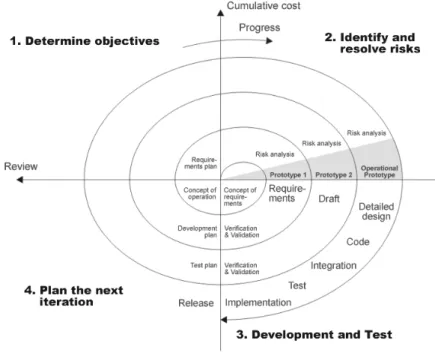
The goal of the spiral model was to combine the advantages of a linear segmented model with the advantages of an iterative process model. The spiral process model provides a framework for such a process, most commonly seen combi-nations are evolutionary vs. waterfall. Another way of looking at this model is a waterfall model with each phase preceded by risk analysis [13]. Boehm [14] defines risk management as ”a discipline whose objectives are to identify, address and eliminate software risk items before they become either threats to successful software or a major source of expensive software rework” This model is recommended when developing large, complex systems. It is seen in Figure 3.3, the figure has approximate explanations marked by 1,2,3 and 4.
Advantages of this model includes risk driven development, since each time the process enters the second quadrant a risk analysis is performed. There is not
3.2. DEVELOPMENT MODELS
Figure 3.3: Boehms Spiral Model (picture source: http : //www .wikipedia.org).
a heap overhead of documentation, this model is quite flexible and it includes prototyping.
There are a couple of disadvantages, for one the model relies on expertise. Also the model is not explicitly guided; there are no clear objectives, constraints or alternatives.
3.2.4
Iterative Enhancement Model
The Iterative enhancement model is an iterative linear sequential model with philosophy from prototyping. In order to use this model the software must be broken down into modules for each increment to work (see Figure 3.4). The first module developed should be the core module. And the later on in the development you get, the modules contain more and more fine grained and advanced functions.
This advantage of this process is feedback from an early increment can im-prove later increments it has short intervals which increase moral.
This process however can also suffer from shared errors/faults which when found in a late increment if forces rework of the earlier increments. This type of process cannot easily be applied on all projects and it suffers from overhead due to switching etc.
3.2.5
V-model
The V-model is a variant of the waterfall model that demonstrates how the testing activities are related to the design and analysis [11]. It is shown that the tests on unit and integration either prove or find flaws in program design –
3.2. DEVELOPMENT MODELS
Figure 3.4: The Iterative Enchancement Model.
Figure 3.5: The V-model.
system testing evaluates system design (see Figure 3.5). When a fault/flaw/error is found in a testing phase there is no need to redo all of the process steps.
The V-model is a bit less ”costy” than the waterfall model, it is a semi linear model. The possibly biggest advantage is, the reason it is called ”Validation and Verification model”, the constant validation and verification.
Although it still suffers from a long time from requirements to testing, it requires many different project roles and is mostly fitted for longer projects.
3.2.6
Extreme Programming
Extreme programming [15] is one of the most well known agile developments, as such communication with the customer is one of the core values in Extreme Programming. The others are simplicity and testing. Extreme programming is a test driven development in the way that the programmers write their own tests before or at the same time as they write the actual code. One of the most
3.2. DEVELOPMENT MODELS
common reasons for software projects being late is lack of communication, the requirements does not match the costumers original ideas or the algorithms are too fast/slow. With a costumer on site to see the progress and test the new features/GUI as they are developed removes this uncertain outcome. Time is most often of the essence and there is no time to find the best solution to all the problems, therefore Extreme Programming says to find the easiest solution and if there is time re factor it.
The clear advantages of Extreme Programming are its short iterations and fast development pace, just solve the problem at hand and move on. If there is time a programmer will re factor the code. The customer is on site and controls where the project is heading. The programming is done in pairs, which means that two programmers sit side by side and solve the problems.
With great advantages comes disadvantages, the quick pace leaves almost no time for documentation, the lack of structure makes this model only suitable for small groups and it requires a customer on site.
3.2.7
Other Process Models
There are several more process models, some more famous and some less famous. Amongst others are several different mutations of the waterfall model, with prototyping and with step by step feedback. There are other agile methods such as Scrum. Depending on the project layout some are more important than others but there is no single solution for all projects.
3.2.8
Model vs. Model
To get a grip on how the different development models actually compare to each other a spider web graph can be drawn with some of the relevant properties. The relevant properties in Figure 3.6 were found to be how much time is spent on some things, how much overhead is found in some parts and how much the customer (or product client) is involved during the process. Note that some of the values can be seen as ”bad”, such as time between requirements specification and test/product.
To fully understand how these spider graphs work we examine the V-model, located in the top left corner. This is a graph over how the V-model is distributed according some basic principles. Beginning at the top and going clock wise we see that this model requires quite a lot of documentation, there is some but not much customer involvement. The time from the start of the project until it is a product is quite long and the iteration lengths are quite long. This model is scalable to large project, there are few iterations, risks are weighed but the project is not oriented by them, it has tests but the main time is not spent on them. The project is easily maintained, if the project is started it is always feasible, there is quite a lot of documentation overhead but not so much overhead due to implementation. Overall there is some project overhead, there is experience exchanged in and between projects but not so much most of the experience is kept to the person finding it. There is an abundance of roles and there is a large gap of time between when specifications are written and when they are tested.
3.2. DEVELOPMENT MODELS
Chapter 4
Formal Specifications
This chapter will explore what requirements are, how to write specifications for requirements and some formal languages that exist for this purpose.
4.1
Requirements
A requirement is a capability that must be met or possessed by the system or software. Testing is an efficient way to check if the system or software meets a certain requirement. However throughout history requirements have been hard to test for several different reasons mostly due to poorly defined and not measurable requirements [16, 17]. One simple example of a poorly written requirement is:
”The execution should be fast.”
How do we define ”fast”? According to what standard should the execution be ”fast”? In animation rendering a couple of hours can be considered fast but update speed of a screen might be slow if it takes 2ms. Requirements can however be more sophistically written and still not describe the system/product. For example:
”The program should calculate salaries and income tax for each em-ployee according to normal tax codes.”
This does not regulate how to get normal tax codes, according to what standard, if this should be done automatically, always, manually or periodically (when salaries are sent out). It does not regulate if this is a function accessed by a button in the GUI or if it is a stand-alone command. In order to create qualita-tive requirements one should have a more formal way of describing the require-ments. There are many different ways of formally describing requirements, from the simplest way of following checklists when writing requirements to hardcore mathematical logic based languages for requirements (such as Haskell [18, 19]).
4.2
Specifications
To establish a good products through requirements they must be specified cor-rectly [17]. The specification is one of the communicational routes between
4.3. DIFFERENT WAYS TO FORMAL SPECIFICATIONS
costumer and developer. Specifications should:
• explain what is needed, not how to achieve this. • not be stated more than once. 1
• not have any missing data.
• have only one possible interpretation. • not contradict any other requirements. • not contain unnecessary data.
• be feasible.
• be understandable for all concerned parts. • be testable.
For real-time systems a couple of other aspects [20] should be considered:
• Model nonfunctional requirements as a part of the specification models, especially timing properties.
• Omit hardware and software assignment in the specification (another as-pect of design rather than specification).
• Be consequent in abstraction and levels of refinement across models. There are several different possible routes to achieve this, the most simple one is to make this list into a checklist and iterate over all the requirements. Checklists are proven to only work during a period of time, most often until the person handling it thinks he/she knows all of the steps by nature. Therefore other operation methods have emerged, languages specifically made for specifi-cations have been written, such as Z (see Section 4.3.2). The unified modeling language [21] has been used for this as well, with use-case diagrams and other types of models. Proprietary software has been developed in the same philoso-phy as using UML, for example Rational Rose Data Modeler developed by IBM [22].
4.3
Different Ways to Formal Specifications
As mentioned in Section 4.1 there are several different ways of writing more or less formal specifications, in this section some of the more and less commonly used ways are presented.
4.3. DIFFERENT WAYS TO FORMAL SPECIFICATIONS
4.3.1
Mathematical Logic
The nature of mathematics is to describe behavior in a simplified manner. Us-ing a subset of mathematics, namely mathematical logic, we can describe any computer system or automaton. To describe behavior several aspects of logics would be needed, for example we would need to know predicate logic to form functions such as:
∃ xP (x ) (4.1)
Where we could define the function P(x) as x being an odd value. Propositional logic would also be needed in order to form theorems such as:
A + B = B + A (4.2)
For dynamic systems, systems which output change depending on time or time based logic, temporal logic would also be needed. A temporal logic is a logic in which temporal modalities can be expressed. Simple logical statements as ”the system works” are constant but the truth value varies over time. Temporal logic can express statements containing operators such as ”until” and ”eventually”, using temporal logic we can describe statements such as ”the system will work until someone breaks it”, ”the system will always work”. The easiest way to realize temporal logic is by referencing to a state-machine where the truth value is depending on which state it has transcended into.
There are clear advantages of using this kind of formality to describe behavior and requirements. Using a functional programming language such as Haskell [18, 19] the behavior can be tested long before it is implemented, also there exists possibilities to automatically derive test cases. However, Mathematicians are seldom found as authors or readers of requirements and their skills are not often found in the common workplace.
All of the following formal specification languages are either tightly coupled with mathematics or can be formally verified by mathematics. Though all of the following representations are ”simpler” than sheer mathematics.
4.3.2
Z
One of the more known formal specification languages is Z [23], pronounced, and sometimes written, Zed.
”The Z notation is a formal specification notation based on set theory and predicate calculus.” [24]
In short term Z is an application of mathematical logic with its own syntax. It is easier to explain through a small example rather than explaining the correct syntax, the syntax can be found in [23]. The example is a disk storage to which you can write. In Z this disk storage could be written as the DiskStorage-schema below. First, the values used are declared, they can be internal, inputs or outputs. Below the line is where a set of rules are stated.
4.3. DIFFERENT WAYS TO FORMAL SPECIFICATIONS DiskStorage contents : Z capacity : Z reading : Z danger level : Z light : Light states contents ≤ capacity
light = ON ⇔ reading ≤ danger level reading = contents
capacity = 200 danger level = 30
Reading this figure would textually be: Diskstorage has a capacity of 200, when there are only 30 or less left a light will be lit. Also, contents can never exceed the capacity level and it is only possible to read existing contents. To facilitate this disk storage we need to define a writing operation, this is done in StorageOK. StorageOK has amount as an input and a requirement that the current contents of the disk storage plus this amount is not greater than the capacity of the disk storage. If this is so, then the disk storage will be updated (the delta sign means that this function will change the object) according ”new contents is the old contents plus the amount”.
StorageOK ∆DiskStorage amount ? : Z
contents + amount ? ≤ capacity contents0= contents + amount ?
But this is not enough to create a robust system. There is a need to have the corresponding, but erroneous, definition as well. NotEnoughDiskSpace is defined to not change DiskStorage (Xi means that no change will be done) but return an array of chars (for simplicity it is here called MSG). The result! is only given if capacity is less than the contents plus the new amount.
NotEnoughDiskSpace ΞDiskStorage amount ? : Z result ! : MSG
capacity < contents + amount ?
result ! = ‘Notenoughdiskspace, savecanceled0
A robust definition of the entire functionality is written according to the following line.
WriteToDisk= StorageOK ∨ NotEnoughDiskSpaceb
This means that WriteToDisk is either StorageOK or NotEnoughDiskSpace, there is no other option for it.
4.3. DIFFERENT WAYS TO FORMAL SPECIFICATIONS
Z has been used with timing for real-time etc. – although not very widely due to the requirements. It can also be used to automatically derive test cases [25] and see whether or not algorithms work.
4.3.3
Unified Markup Language
UML, or Unified Markup Language, is a commonly known standard general purpose modeling language [21]. It is used for modeling a system, which is more than graphical representation of the parts, on different abstraction levels and with different approaches. Some of the more known, and used, behavior methods defined in UML are State Machines, Use Cases, Activity, and Inter-action Diagrams. UML is also used for structural diagrams, including but not limited to, Class, Object, Package and Component diagrams.
Since the founding concept of UML has evolved other methods has taken advantage of new notations, also new methods have been created solemnly based on UML. IBM Rational Unified Process is probably the most famous of them. UML has been the foundation for several more specific solutions such as the Abstraction Method.
4.3.4
Message Sequence Chart
Message Sequence Chart, now addressed as MSC [26], is an interaction dia-gram. It is very similar to UML but is a child of Specification and Description Language, SDL. SDL is a formally complete specification language, which allows code to be generated from the charts. SDL is defined by the Telecommunication Standardization Sector, ITU-T [27], and was initially focused on telecommuni-cation. SDL has lately been applied on general real-time applications. At the release of the new standard SDL-2000 there was also an UML-profile called ”Sequence Diagram” [28].
Message sequence charts are used to describe behavior in a system by a series of ”calls” and ”self calls” (Figure 4.1). This can be used to capture the requirements of a system if modeled correctly. In Figure 4.1 we can see that a user (or agent) wants to see today’s calendar, the computer calls the server and wants to login. After the login it requests today’s activities, after the response it logs out and terminates.
However MSC does not require certain behavior in any of the scenarios but only gives a representation on how a good execution would act, it does not say that is has to be this way. These inconsistencies have lead to an extension called Live Sequence Charts.
4.3.5
Live Sequence Charts
Live Sequence Charts [29], abbreviated LSC, have introduced several capabilities such as temporal attributes and prerequisites for execution. LSC is able to handle intra-object behavior, which is one of the things MSC lack.
The framework provides means of creating while- and for- loops through bounded and unbounded looping when combining this with cold conditions (if-statements).
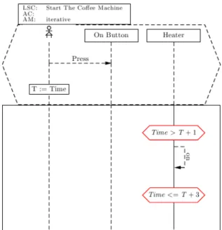
A simple example can be seen in Figure 4.2 where there is a user using an interface button and the system is handling this. Described in order of
appear-4.3. DIFFERENT WAYS TO FORMAL SPECIFICATIONS Computer Server calendarToday() login() getTodaysActivities() logout() LoginResponse response
4.3. DIFFERENT WAYS TO FORMAL SPECIFICATIONS
Figure 4.2: A simple example illustrating LSC.
ance we have involved parts (user, systems), the prerequisites (incl. actuating and setting time) and then the actions (including the actuality). To describe what actually happens, with a top down perspective, first the user presses the On-button. This is also a prerequisite for the execution in the ”box” to happen. There are timed sanity checks to see if the heater should be turned on or not. There are two checks, the first one is set to abort if there has been less time than T+1 from the user pressed the button until the heater is turned on. The second one is set to abort (and make sure the heater state was not altered) if it takes too long to turn the heater on.
Looking at the structure of LSC it is clear that the semantics of LSC makes it easy for anyone to see what should happen in a system. This is ideal when development and testing is separated into groups, due to the simple fact that communication will be made easy and undependable of previous knowledge and experience.
Chapter 5
Document Version Control
Revision control software is used to manage and keep track of the complexity of software under development. Modern software is often very complex with developers located at separate geographical locations. Without revision control software it would be very difficult to keep track on changes as the software evolves. Revision control does not exclusively refer to software revision control. Management of documents or any other computer file also falls under revision control.
5.1
How it Works
A basic revision control software contains the following elements:
• Client - The computer which connects to the repository.
• Repository - The database which stores the revision controlled files. Can either be centralized or distributed.
• Trunk - The root folder in the repository.
• Working copy - The local copy of the files on the client computer. The revision control software manages changes in files by having a repository which a client connects to with different requests. The repository stores the managed files and keeps track on them by attaching a revision number to each file. Common actions of a revision control software:
• Add - Start version controlling a new file and adds it to the repository. • Branch - Makes a copy of the file to be worked on in a different branch. • Changelog - Displays a list of changes made to the file.
• Check in - Puts the file in the repository under a new revision number. • Check out - Gets the latest version of a file from the repository. • Conflict - Occurs when pending changes to a file overlap.
5.1. HOW IT WORKS 1 1.1.1 1.2.1 1.2.2 2 Branching Merging
Figure 5.1: Revision control history tree.
• Diff - Displays the differences between two files. • Head - The latest revision in the repository. • Merge - Joins the changes from one file to another.
• Revert - Cancels the local changes made to a file and replaces it with the latest version of the file from the repository.
• Revision - Displays the version of a file.
• Update - Gets the latest version of all files in the repository.
When a change is made to a file, and it is checked in, the revision number increases. Each revision is linked to the person who made the changes associated with that particular revision and a time stamp. Revision control software are often very versatile tools with capabilities beyond the actions described above. The traditional revision control model uses a centralized server for storage of the repository and to execute the revision control functions on. Since the begin-ning of the 21th century revision control software with a distributed repository solution has appeared [30]. Distributed revision control uses a peer-to-peer sys-tem where every copy of the project keeps all the related metadata and project history.
Figure 5.1 visualizes the history tree of a revision controlled project, showing branching and merging.
5.1.1
Parallel Development
The ability to maintain several development branches simultaneously is one of the most powerful features of revision control. A simple example of how it works will follow.
5.1. HOW IT WORKS
test.txt Lorem ipsum dolor sit amet,
mutationem adipiscing
A ”release” is made of the file - release 1. When a file is released a tag is created in the repository which marks the state of the file the time it was released. The tag is associated with a new development branch. This new branch will only be used for maintenance of the newly made release while the trunk file will be used for further development.
Development continuous and test.txt (in the trunk) now contains:
test.txt Lorem ipsum dolor sit amet,
mutationem adipiscing elit, sed diam nonummy nibh euismod
A defect is now found in release 1. The word ”mutationem” is supposed to be ”consectetuer”. The fastest way to fix this is to release a patch for release 1. Waiting for a stable release 2 would take too long. Release 1 is downloaded from the maintenance branch and the defect is corrected.
test.txt Lorem ipsum dolor sit amet,
consectetuer adipiscing
Release 1.1 is now created from the maintenance branch with the defect cor-rected. Release 1.1 does not include any of the new development. In parallel to this patch fix, development could continue unhindered in the main development line.
It would be redundant work to fix the defects in release 1 once more in release 2. The solution is to merge release 1.1, which contains the correct code, with the main development line before release 2 is created. ”Conflicts” occur when bug fixes overlap the new development. Usually the symbol ”<<<<<<<<” marks where a conflict starts.
test.txt Lorem ipsum dolor sit amet, <<<<<<<
mutationem adipiscing elit, sed diam nonummy nibh euismod =======
consectetuer adipiscing >>>>>>>
Conflicts found have to be manually resolved. When all conflicts are resolved the file is committed and the merge is complete. A defect-free release 2 can now be created. Figure 5.1 shows the development in parallel with maintenance and finally the merge between the two, resulting in release 2.
5.2. SIMULINK MODELS
Figure 5.2: This is how Simulinks block diagramming tool presents the model to the user.
5.2
Simulink Models
Simulink is a part of MATLAB [31], developed by Mathworks. It is a develop-ment environdevelop-ment for modeling, analyzing and simulating embedded and mul-tidomain dynamic systems. Simulink uses a graphical block diagramming tool as the interface to the user. The close integration with the rest of MATLAB provides tools to customizing the modeling environment, create batch scripts and develop algorithms to name a few.
Figure 5.2 illustrates Simulinks block diagramming tool.
5.2.1
The Model File Format
The Simulink model file is a structured ASCII file. The file is organized in a hierarchical order and describes the model with keywords and parameter-value pairs.
The model file is composed by seven different sections.
• Model Section - The model section contains all other sections; this is at the top of the hierarchy. Parameters such as the model name and configuration set parameters are defined here.
• Simulink ConfigSet Section - Identifies the active configuration set of the model.
• BlockDefaults Section - The default values for common block param-eters in the model are defined here.
• BlockParameterDefaults Section - The default values for block-specific parameters are defined here.
• AnnotationDefaults Section - The default parameters for all annota-tions in the model are defined here.
• LineDefaults Section - The default parameters for all lines in the model are defined here.
• System Section - Each system in the model, both top-level system and subsystem, is described in a separate system section. All system level parameters are defined here.
5.3. REVISIONING MODEL FILES
5.3
Revisioning Model Files
It is somewhat problematic to properly revision control Simulink model files. This is primarily due to a couple of reasons. The fact that the model files are composed the way they are and how they are manipulated by the user are two of the reasons. The user manipulates the model primarily through the Simulink block diagramming tool. Changes made to a block in the model can result in changes widely spread throughout the actual model file. The user receives no visual feedback on the changes made by his actions to the text content in the file. This can be compared to a programmer who is writing source code directly to the file he is manipulated, he or she sees every single change made to the file directly.
This leads us to the next reason of the problem with revision controlling Simulink models. As described in Section 5.2.1, the model files are structured text files, hence there should be no problem comparing two model files with an arbitrary diff-tool to display the differences between the files. They can be compared with a diff-tool without problem, the problem lies in presenting the differences to the user. As the user has exclusively worked on the model via a graphical user interface he or she will have no idea about what to make of all the changes in the structured text presented by the diff-tool - which renders traditional diff-tools practically useless when comparing models.
The reasons described above makes revision control of Simulink model files a lot less effective than revision control of traditional software source code files. Specific changes to models cannot be tracked and this makes parallel develop-ment virtually impossible.
5.3.1
Document/File Dependencies
Having multiple users work on the same project creates several dependencies and potential pit falls it puts a great responsibility on each user to always maintain a correct repository, which means working code and related binaries. Using models create another potential error in this chain, which means the model must be at the same version as the generated code and the binary.
Chapter 6
Proposed Improvements
In this chapter focus is on specific improvement proposals, shown in Figure 6.1, how they are implemented and how their performance is measured. Figure 6.3 gives a picture on how the improvement suggestions are connected to the devel-opment process seen in Figure 6.2. The connection maps show how entangled this integration is, but also shows that there are no extra formal steps. Figure 6.2 is defined as the original graph and the methods are introduced into Figure 6.3. The graphs contain a black circle which is the concept, in the original graph there is only one and it is called Software Development Process. This concept has several steps, or contains several parts; these are gray medium sized circles which are connected to the concept. The steps can, in some cases, be divided into several sub steps such as Bug Fixes and Updates in the Maintenance step. In the Figure 6.3 the new methods are introduced, there are connections from the introduced methods to the steps, or sub steps, where they apply. The meth-ods are color-coded for readability and the involved parts are colored by this. For example when the Control Group is applied on a step, or part, that step, or part, goes from gray to gray/red, introducing Linked Documents to the same step makes the part, or step, gray/red/green as seen in Acceptance Testing, System Design, Program Design and Implementation.
Model Compare (blue) is used mainly in the architectural parts of system and program design as well as in maintenance. The Control Group (red) has an effect on all of the steps in the software development process, Linked Documents (green) also affects all the steps. Live Sequence Charts (pink) are used during the formal requirements and the testing.
Note that even though none of the suggested changes directly apply to test-ing, most of them affect the testing part of the software development process.
The improvement ideas were applied to an already finished project, but the different project phases were altered all the way from the first phase to match the suggested improvements.
6.1
Document Inconsistency
Document inconsistency is a wide spread problem, often found in larger estab-lishments, projects and companies. If a company has different people for the different stages in the development process it is crucial that the correct
infor-6.1. DOCUMENT INCONSISTENCY
Figure 6.1: Improvement proposal plan.
mation always is presented at the different stages. For example; someone in the design group updates a model and does not generate code for this model. The implementation group will implement the latest generated code (not from the models) and hand over to the test group. The test group is going to test this according to the latest model and falsely see that the code is erroneous or, even worse, do not see that the code/model is erroneous.
6.1.1
Method Description
The method suggested here, ”linking documents”, is related to revision control and it was implemented in the trunk of all of the files related to the work of this thesis. Several revision control systems support arbitrary code execution pre/during/post commit/update executions [32, 33]. During this test we used Bazaar. We also implemented our rule set under version management, to make sure that even if we would revert a version or two the rule set would be correct. Different rules, or relations, were implemented which could be applied to files. Relations could be either ”one to one”, ”one to many” or ”many to many”. Other, in this case irrelevant, relations, such as ”none to one” or ”none to none” were overseen.
The used relations are:
(1) A change in fileA requires change in at least one of fileB, ..., fileN.
(2) A change in fileA requires change in all of fileA, ..., fileN.
(3) A change in fileA or fileB mutually requires a change in the other.
Where, in (1), fileA could be a .pdf file related to its source code, possibly some .tex files. Thusly if pdf is updated the source would have to be changed
6.1. DOCUMENT INCONSISTENCY
6.1. DOCUMENT INCONSISTENCY
6.2. SIMULINK MODELS - PARALLEL DEVELOPMENT
as well. This could be checked the other way around (2), if the .pdf file is changed all of the related .tex-files must be changed. And, in (3), the relations can describe any two (or more) files that are mutually related such as a binary and a source code file. Changes in any of the two would require changes in the other. Files that need this type of relationship might be a binary and a source code.
6.1.2
Method Results
As mentioned in 6.1.1 the idea of ”linking documents” was validated by im-plementing it in the trunk containing all of the files related to the work of this thesis. During the time-period which these files were actively part of the work, spanning almost half a year, no document inconsistencies were encoun-tered. Although there were several occurrences during the first period of time where possible inconsistencies were found and caused a correction before sub-mit/commit.
6.2
Simulink Models - Parallel Development
One of the problems derived from the survey presented in Section 1.2.2 was the problematic issue of Simulink models and parallel development. In this chapter it will be described how the problem and possible solutions was investigated.
Source code is managed with a revision control solution which keeps tracks of changes in the code. The main problem is the file type of the models. Keeping track of changes in a model file is not as simple as keeping track of changes in an ordinary source code file. As described in Section 5.2.1 Simulink model files are structured in a specific hierarchical way. A seemingly small change made to the model via the graphical user interface of Simulink produce changes in several sections of the model file itself. Keeping track of the changes made to the model using an ordinary diff utility would be very indistinct. For this reason, traditional parallel development methods using a revision control system is very complex and ineffective when working with models.
6.2.1
Method Description
Existing solutions that would make parallel development, when working with models, easier were investigated. The two most flexible and accessible solutions were evaluated. Each tool was used to find the differences in different releases of a modeled system. The target system was moderately complex, composed by several thousand blocks and connecting lines. The most recent release of the model was compared against three earlier releases to visualize modifications and added features since the old releases.
The following two tools were evaluated.
• XML-compare MATLAB Report Generator software includes the tool XML-compare. XML-compare is capable of processing two XML text files and presents the differences in either report form or in a hierarchical view. XML-compare can also generate a report over the differences between the two files.
6.2. SIMULINK MODELS - PARALLEL DEVELOPMENT
Figure 6.4: Differences visualized using Model Compare.
• Model Compare Model compare is a model comparison software devel-oped by dSPACE. It allows you to compare two Simulink models. Model compare identifies and visualizes differences between corresponding blocks, lines, stateflow states, properties and Simulink annotations. There is also an option to merge the identified differences.
Even though Model Compare is a stand-alone program, it still uses the graphical user interface of Simulink for the graphical visualization of the differences. Figure 6.4 shows how Model Compare presents color coded model differences visually, using Simulink. Figure 6.5 shows the hierarchi-cal overview in Model Compare.
6.2.2
Method Results
The tools were used to identify and present the differences between the most recent release of a model, and each of the three previous releases nearest in time - starting with the release furthest away. The expected results were a clear view of how the number of differences decreased for each comparison. The differences themselves were also reviewed in detail to verify the correctness of the results.
XML-compare was not able to execute all the comparisons. The program constantly crashed during the loading phase of the biggest model file. This re-sulted in an incomplete collection of evaluation result data from XML-compare. The comparisons, using less complex models, which could be executed, delivered overall unsatisfying results.
Model Compare was able to execute all tasks throughout the evaluation. Figure 6.6, 6.7 and 6.8 illustrates the decrease in identified differences as the
6.2. SIMULINK MODELS - PARALLEL DEVELOPMENT
6.3. MANAGING PROCESS INFORMATION
Figure 6.6: Number of differences - most recent release compared to a 5 month old release.
previous releases approaches the most recent release of the model.
Advantages and disadvantages of the tools
Model Compare
+ Is capable of merging differences between two different models. + Most changes are visualized in an structured and organized way. + Can produce good and practical statistics.
+ Customizable - filter settings etc.
+ Can handle very large and complex model files.
– Changes in large stateflow statements can be hard to comprehend.
XML-compare + Is a part of Simulink.
– Is not capable of merging differences between two different models. – Useless when comparing larger models.
– Unclear presentation of differences. – No customizable settings.
6.3
Managing Process Information
Almost all of the software development processes create an abundant amount of documents and sometimes complex information. These documents are often deliverables sent between the levels of the software development process to be used in the stages to follow. Problems with these deliverables, for example errors within the documents, often leads to slower progress in later stages of the development.
There are occasions where the people responsible for this documentation are either unaware of exactly what it should contain or just skip parts of it to
6.3. MANAGING PROCESS INFORMATION
Figure 6.7: Number of differences - most recent release compared to a 3 month old release.
Figure 6.8: Number of differences - most recent release compared to a 1 month old release. No new functionality was introduced between these two releases, which Model Compare correctly reported.
6.4. FORMAL SPECIFICATIONS
finish early with the documentation. The bigger the company is the easier it is to hide such flaws, especially if there are just a few, closely coupled, people working with that input/output-data. In order to handle the documents there must be output-validation to ensure that all deliverables are passed between the different stages of the development process and that they are correct.
6.3.1
Method Description
The solution suggested here to increase the quality of the process information is to implement a control group. The objective of the control group is to control the deliverables between each step of the development model. Figure 6.1 illustrates the suggested implementation of the group. Where errors are found in the documentation the group is to notify the responsible person rather than correct the error themselves. It would be a far too time consuming task for the control group. More importantly, by simply notifying the responsible part of their mistake, the organizations maturity will grow with time and the need for a control group will gradually decrease.
The control group should consist of persons with different roles in the soft-ware development model. It should be dynamic and does not necessarily consist of persons involved in the specific project that the group controls. This will en-courage experience sharing between, and within, projects which can prove to be very rewarding.
Since only one method, concerning this topic, is suggested, it was imple-mented as a part of the workflow throughout the work conducted to achieve the results in this thesis. During the thesis work this control group, consisting of the thesis authors themselves, validated all the output-data and gave feedback on possible errors in it.
6.3.2
Method Results
As the work progressed, a notable sum of errors was found in various relevant documentation. If this was done in a real software project the responsible ones would have been notified and urged to correct the errors. In this case, were all of the documents did not originate from the thesis work itself, middle ground had to be found. All of the errors found associated with the documentation that was generated from the thesis work were treated in accordance with the control group. Errors found in documentation gotten from other sources were merely recorded.
At the end of the work, the results were good. Several errors had been found, and where possible corrected, during the work. Errors ranging from incorrect requirements to missing documents were discovered by the control group.
6.4
Formal Specifications
The need for a formal specification is quite obvious; specifications are mostly non verbal which leaves room for misinterpretations. Specifications are going to stay at the company for as long as at least one customer still owns and uses the product related to the specification. This imposes a possible extreme gap in