Mälardalen University Press Dissertations No. 190
SIMULATION OF INDOOR RADON AND ENERGY RECOVERY
VENTILATION SYSTEMS IN RESIDENTIAL BUILDINGS
Keramatollah Akbari 2015
School of Business, Society and Engineering Mälardalen University Press Dissertations
No. 190
SIMULATION OF INDOOR RADON AND ENERGY RECOVERY
VENTILATION SYSTEMS IN RESIDENTIAL BUILDINGS
Keramatollah Akbari 2015
Mälardalen University Press Dissertations No. 190
SIMULATION OF INDOOR RADON AND ENERGY RECOVERY VENTILATION SYSTEMS IN RESIDENTIAL BUILDINGS
Keramatollah Akbari
Akademisk avhandling
som för avläggande av teknologie doktorsexamen i energi- och miljöteknik vid Akademin för ekonomi, samhälle och teknik kommer att offentligen försvaras fredagen den 18 december 2015, 10.00 i Pi, Mälardalens högskola, Västerås. Fakultetsopponent: Associate Prof. Anestis Kalfas, Aristotle University of Thessaloniki
Akademin för ekonomi, samhälle och teknik Copyright © Keramatollah Akbari, 2015
ISBN 978-91-7485-236-3 ISSN 1651-4238
Mälardalen University Press Dissertations No. 190
SIMULATION OF INDOOR RADON AND ENERGY RECOVERY VENTILATION SYSTEMS IN RESIDENTIAL BUILDINGS
Keramatollah Akbari
Akademisk avhandling
som för avläggande av teknologie doktorsexamen i energi- och miljöteknik vid Akademin för ekonomi, samhälle och teknik kommer att offentligen försvaras fredagen den 18 december 2015, 10.00 i Pi, Mälardalens högskola, Västerås. Fakultetsopponent: Associate Prof. Anestis Kalfas, Aristotle University of Thessaloniki
Akademin för ekonomi, samhälle och teknik
Mälardalen University Press Dissertations No. 190
SIMULATION OF INDOOR RADON AND ENERGY RECOVERY VENTILATION SYSTEMS IN RESIDENTIAL BUILDINGS
Keramatollah Akbari
Akademisk avhandling
som för avläggande av teknologie doktorsexamen i energi- och miljöteknik vid Akademin för ekonomi, samhälle och teknik kommer att offentligen försvaras
fredagen den 18 december 2015, 10.00 i Pi, Mälardalens högskola, Västerås. Fakultetsopponent: Associate Prof. Anestis Kalfas, Aristotle University of Thessaloniki
Abstract
This study aims to investigate the effects of ventilation rate, indoor air temperature, humidity and using a heat recovery ventilation system on indoor radon concentration and distribution.
Methods employed include energy dynamic and computational fluid dynamics simulation, experimental measurement and analytical investigations. Experimental investigations primarily utilize a continuous radon meter and a detached house equipped with a recovery heat exchanger unit. The results of the dynamic simulation show that the heat recovery unit is cost-effective for the cold Swedish climate and an energy saving of about 30 kWh per floor area per year is possible, while it can be also used to lower radon level.
The numerical results showed that ventilation rate and ventilation location have significant impacts on both radon content and distribution, whereas indoor air temperature only has a small effect on radon level and distribution and humidity has no impact on radon level but has a small impact on its distribution.
ISBN 978-91-7485-236-3 ISSN 1651-4238
Abstract
This study aims to investigate the effects of ventilation rate, indoor air temperature, humidity and using a heat recovery ventilation system on indoor radon concentration and distribution.
Methods employed include energy dynamic and computational fluid dynamics simulation, experimental measurement and analytical investigations. Experimental investigations primarily utilize a continuous radon meter and a detached house equipped with a recovery heat exchanger unit. The results of the dynamic simulation show that the heat recovery unit is cost-effective for the cold Swedish climate and an energy saving of about 30 kWh per floor area per year is possible, while it can be also used to lower radon level.
The numerical results showed that ventilation rate and ventilation location have significant impacts on both radon content and distribution, whereas indoor air temperature only has a small effect on radon level and distribution and humidity has no impact on radon level but has a small impact on its distribution.
In the world, there is only one excellence and
one sin, the knowledge and the ignorance.
(J.M. Rumi, 1207–1273)
Acknowledgments
This thesis has been carried out at the Future Energy Center at Mälardalen University..I wish to express my gratitude to my previous main supervisor, Prof. Jafar Mahmoudi and my current main supervisor, Associate Prof. Kon-stantinos Kyprianidis for their continued encouragement and valuable sug-gestions during this work, for offering the possibility to do my PhD. studies in this field and for their support. I am also grateful to my co-supervisor Dr Robert Öman who supported me with many informative discussions. I would also like to include my gratitude for friendly cooperation to Prof. Erik Dahlquist, Bengt Arnryd and Adel Karim. Also, I am grateful to Dr David Ribé for the English language corrections, Mikael Gustafsson and Dr Jan Pourian and Dr Hamid Nabati for their valuable advice and assistance.
I would like to thank the Academic Center for Education, Culture and Re-search (ACECR) and the Technology Development Institute (TDI) for finan-cial support of this thesis. Furthermore, I am deeply indebted to cooperation from the environment section of Västerås Municipality, JBS, AB Company and EQUA AB for the use of IDA ICE, the Indoor Air Climate and Energy software program. I would also like to show my appreciation towards Hamid Afshar for providing supports and helping to test radon and obtain measure-ment data in his house for an extended period.
Finally, I want to thank my family – the encouragement and support from my beloved wife and our always positive and joyful sons is a powerful source of inspiration and energy. I would like to dedicate a special thought to my parents for their never-ending support.
Abstract
This study aims to investigate the effect on indoor radon concentration and distribution of ventilation rate, indoor air temperature, and humidity when using a heat recovery ventilation system.
Methods employed include energy dynamic simulations and computa-tional fluid dynamics, experimental measurements and analytical investiga-tions. Experimental investigations primarily utilize a continuous radon meter and a detached house equipped with a recovery heat exchanger unit.
The results of the dynamic simulation show that the heat recovery unit is cost-effective for the cold Swedish climate and an energy saving of about 30 kWh per 𝑚𝑚2 floor area per year is possible, while it can be also used to
low-er radon level.
The numerical results showed that ventilation rate and ventilation location have significant impacts on both radon content and distribution, whereas indoor air temperature only has a small effect on radon level and distribution and humidity has no impact on radon level but has a small impact on its dis-tribution.
Summary
The main purpose of this doctoral dissertation is to investigate how the radon level and its distribution in indoor air are influenced by both the ventilation and by different conditions indoors. A heat recovery ventilation system could be a good choice from energy saving and indoor radon mitigation standpoints. The study uses two approaches in parallel. In the first approach, dynamic simulation is used to demonstrate the energy recovery potential. In the second approach, a detailed numerical model is developed and utilised to predict the indoor radon level and distribution with varying levels of ventila-tion rate, indoor air temperature and humidity.
The effect of a heat recovery ventilation system on both energy saving and radon mitigation was investigated in a detached house using IDA, ICE, Indoor Air Climate and Energy software program, analytical investigations and measurements. Then a finite volume method was applied using the com-putational fluid dynamics (CFD) ANSYS FLUENT software.
Although many research studies have been conducted on the effects of ra-don in soil and its properties on indoor rara-don, information about the influ-ence of indoor air conditions on indoor radon behaviour is rather scarce and merits further investigation. Furthermore, traditional methods of measuring indoor radon can only provide rough average values for the whole of a build-ing or a room for an entire year. This is unsafe and unacceptable from the indoor air quality viewpoint. Health organizations also emphasise that any level of radioactive elements such as radon may be carcinogenic.
Through the CFD simulations carried out in this study, the indoor radon level and distribution is predicted throughout a room and particularly in dead zones with insufficient ventilation rate. The simulations provide a good pic-ture of indoor radon distribution and help investigate the effect of different independent variables on indoor radon.
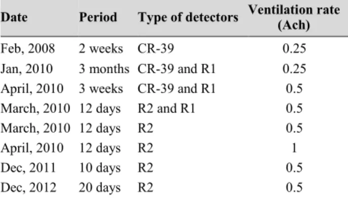
In this study, indoor radon activity concentrations were measured during the cold season for different ventilation rates using a new radon electronic meter (commercially known as R2) which can measure radon, temperature and relative humidity simultaneously. The measurements complement the theoretical analysis performed on the association between indoor radon level and ventilation rate, the height above the floor and economic analysis of installing a heat recovery unit considering life cycle costs.
The results of the dynamic simulation and theoretical analysis confirmed that the heat recovery unit is cost-effective for cold climates like Sweden and an energy saving of about 3,000 kWh per year or about 30 kWh per m2 floor
The numerical simulation results show that ventilation rate and ventilation location have significant impacts on both radon content and radon distribu-tion, whereas indoor air temperature has a small effect on radon level and distribution, and humidity has no impact on radon level but has a small im-pact on its distribution. There was good agreement between analytical, measurement and simulation results concerning the association between indoor radon level, the height above the floor and ventilation rate.
It should be emphasised that this work represents the first step in the field with regard to using CFD to study the sensitivity of indoor radon level and its distribution in small residential buildings. The research is supported by a number of publications as well as unpublished results which are shown for the first time in the main body of this thesis. It is hoped that the present study will serve as a stepping stone for further work in the field by the other re-searchers.
Sammanfattning
Huvudsyftet med denna doktorsavhandling är att undersöka hur radonhalt och dess fördelning i inneluft påverkas av både ventilation och av olika för-hållanden inomhus. Ett fläktstyrt ventilationssystem med en värmeväxlare mellan från- och tilluft kan bidra till både mindre värmeförluster och lägre radonhalt i inneluften. I denna studie används två metoder parallellt. Den första metoden är dynamisk simulering av energibalans med fokus på vär-meväxling. Den andra metoden avser en detaljerad numerisk modell som utvecklats och tillämpats för att förutsäga hur radonhalt och fördelning av radonhalt i inneluft påverkas av uteluftsflöde och inneluftens temperatur och luftfuktighet.
Ett fristående småhus med en värmeväxlare mellan från- och tilluft stude-rades avseende både energihushållning och radonbegränsning med datapro-grammet IDA ICE (Indoor Climate and Energy), med analytiska undersök-ningar och med mätundersök-ningar. För en detaljerad numerisk modell användes sedan en finit volymmetod med CFD (Computational Fluid Dynamics) i dataprogrammet ANSYS FLUENT.
Många studier har gjorts om markradon och dess allmänna påverkan på radonhalten i inneluft. Det finns dock mycket begränsat med information om hur olika förhållanden inomhus kan påverka radon i inneluft och detta moti-verar vidare undersökning. Dessutom brukar traditionella mätmetoder för radon bara ge medelvärden för ett visst rum eller en viss byggnad ofta upp-skattat för ett helt år. Detta kan sägas vara osäkert och oacceptabelt med hänsyn till den stora betydelsen av inneluftens kvalitet. Hälsoorganisationer betonar också att all joniserande strålning från till exempel radon kan vara cancerframkallande.
Simuleringar med CFD användes i denna studie för att förutsäga radon-halten och dess fördelning i rum som även innehåller stagnationszoner med mycket dålig ventilation. Simuleringarna kan ge en bra uppfattning om donhaltens fördelning och kan även visa hur olika variabler inverkar på ra-donhalten.
Samtidiga mätningar av radonhalt, lufttemperatur och relativ luftfuktighet gjordes med olika uteluftsflöde vintertid med en ny elektronisk radonmätare som kommersiellt är känd som R2. Mätningarna kompletterar den teoretiska analysen avseende sambandet mellan radonhalt å ena sidan och uteluftsflöde och höjd över golvet å andra sidan, och även när det gäller en ekonomisk analys med livscykelkostnader avseende värmeväxling.
Resultat från den dynamiska simuleringen och den teoretiska analysen bekräftar att värmeväxlaren i detta fall är kostnadseffektiv för kalla klimat
såsom i Sverige med en möjlig energibesparing om ca 3 000 kWh per år eller ca 30 kWh per m2 golvarea och år.
Resultat från de numeriska simuleringarna visar att uteluftsflöde och ven-tilationsdonens placering har betydande inverkan på både radonhalten och dess fördelning, medan innetemperaturen har en liten inverkan på radonhal-ten och dess fördelning. Vidare framgår att luftfuktigheradonhal-ten inte inverkar på genomsnittlig radonhalt, men har en liten inverkan på radonhaltens fördel-ning. Överensstämmelsen var god mellan resultaten från analys, mätningar och simuleringar avseende sambandet mellan radonhalt å ena sidan och uteluftsflöde och höjd över golvet å andra sidan.
Det bör framhållas att det här arbetet utgör ett första steg inom området avseende CFD-simulering för detaljerade studier av radonhalt och dess för-delning i småhus. Forskningen stöds av ett antal publikationer samt opubli-cerade resultat som visas för första gången i huvuddelen av denna avhand-ling. En förhoppning är att denna studie kommer att fungera som en språng-bräda för fortsatt arbete inom området av andra forskare.
List of Papers included
This thesis is based on the following papers, which are referred to in the text by their Roman numerals.
I. Akbari, K. & Öman, R. (2013). Impacts of heat recovery ventilators on energy savings and indoor radon level. Management of Environmental
Quality Journal, Vol. 24, No. 5, pp. 682–694.
II. Akbari, K., Mahmoudi, J. & Ghanbari, M. (2013). Simulation of Venti-lation Effects on Indoor Radon. Management of Environmental Quality
Journal, Vol. 24, No. 3, pp. 394–407.
III. Akbari, K. & Mahmoudi, J. (2012). Effects of Heat Recovery Ventila-tion Systems on Indoor Radon. Proceedings of ECOS 2012 - the 25th
in-ternational conference on Efficiency, Cost, Optimization, Simulation and Environmental Impact of Energy Systems, June 26-29, 2012, Perugia, Italy ECOS 2012. Available at: http://www.ecos2012.unipg.it/public/
proceedings/pdf/buces/buces_ecos2012_329.pdf.
IV. Akbari, K. & Mahmoudi, J. (2013). Influence of Indoor Air Conditions on Radon Concentration in a Detached House. Journal of Environmental
Radioactivity, No. 116, pp. 166–173.
List of Publications not included
In completion of this thesis and the papers listed above, ideas, data meas-urements, computations, modeling and simulations, and analyses were car-ried out by the author. I have been assisted by my main supervisor, co-supervisor, reviewers and co-authors in adding further improvements to the work. Papers and other publications excluded from this thesis are as follows.
Licentiate thesis
I. Akbari, K. (2009). Impact of Radon Ventilation on Indoor Air
Quali-ty and Building Energy Saving. Mälardalen UniversiQuali-ty Press. ISBN
978-91-86135-39-3. Available at
http://mdh.diva-portal.org/smash/get/diva2:237857/FULLTEXT01.pdf
Papers
II. Akbari, K. & Mahmoudi, J. (2008). Simulation of Radon Mitigation and Ventilation in Residential Building. Printed in the 49th
Scandi-navian conference on Simulation and Modeling (SIMS 2008).
ISBN-13-978-82-579-4632-6.
III. Akbari, K., Mahmoudi, J. & Öman, R. Ventilation Strategies and Radon Mitigation in Residential Buildings. Submitted to Indoor Air
International Journal of Indoor Environment and Health. ID:
INA-09-09-156.
IV. Akbari, K. & Mahmoudi, J. (2009). Influence of Residential Ventila-tion on Radon MitigaVentila-tion with Energy Saving Emphasis. Scientific Conference on "Energy system with IT" March 2009, Stockholm. ISBN 978-91-977493-4-3.
Table of Contents
1 INTRODUCTION ... 1
Background ... 1
Problem description and motivation ... 3
Aims and objectives ... 4
Methods, limitations and research process ... 4
Thesis outline ... 5
Summary of included papers ... 6
Contribution to knowledge ... 8
2 LITERATURE REVIEW ... 9
Indoor radon levels, energy use and heat recovery ventilation system ... 9
Ventilation effect and Indoor Radon Mitigation ... 12
Radon transport mechanisms and environmental conditions effects ... 12
2.3.1 Radon concentration equation in a ventilated room ... 14
2.3.2 The effects of temperature and humidity on the pressure field .. 14
Radon modeling methods ... 15
3 MATERIALS AND METHODOLOGY ... 17
Materials ... 17
3.1.1 Case study house ... 17
3.1.2 Heat recovery unit ... 18
3.1.3 Radon detectors ... 20
Research methods ... 21
3.2.1 Measurement ... 21
3.2.2 Analytical analysis ... 22
3.2.3 Economic analysis ... 23
3.2.4 Heating degree days (HDD) calculations ... 23
3.2.5 Ventilation loss ... 24
3.2.6 The life cycle cost analysis of heat recovery ventilation system 25 Energy dynamic simulation ... 26
Computational fluid dynamics (CFD) ... 27
4 NUMERICAL MODELING PROCEDURE ... 29
Governing equations used ... 30
Turbulence model ... 34
Boundary conditions and input data ... 35
4.4.1 Inlet Vent ... 35
4.4.2 Outlet ... 37
4.4.3 Outer Surfaces ... 37
4.4.4 Internal Surfaces ... 38
4.4.5 Floor Zone ... 38
The House Plan Geometry ... 39
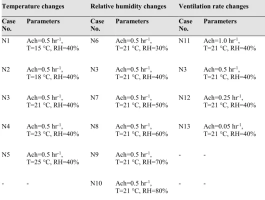
Parameters Variation Range ... 40
Materials Properties ... 41
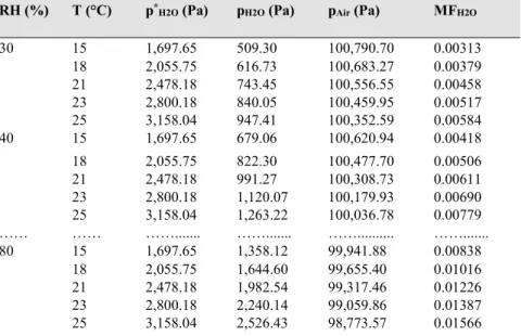
Relative Humidity ... 42
Defined Functions ... 45
Convergence Criteria ... 45
Near-wall treatment ... 46
Mesh Independence Study ... 50
Examination of convergence criteria ... 54
5 RESULTS AND DISCUSSION ... 63
Radon measurement ... 63
Analytical analysis of radon level in the case study house ... 68
Dynamic energy simulation and calculation ... 68
5.3.1 Economic analysis of the heat recovery ventilation unit ... 69
Results and discussion of numerical modelling ... 71
5.4.1 Air Change Rate Effects on Indoor Radon Content ... 71
5.4.2 Temperature Changes Effects on Indoor Radon Concentration . 76 5.4.3 Effects of Relative Humidity Changes on Indoor Radon Concentration ... 79
Model validation and result comparison ... 81
6 CONCLUSIONS AND FUTURE WORK ... 83
Dynamic simulation and heat recovery analysis ... 83
Numerical Simulation ... 84
Future work ... 85
REFERENCES ... 87
APPENDICES ... 91
APPENDIX A: IDA,BOUNDARY CONDITIONS AND INPUT DATA ... 93
APPENDIX B: RADON TRANSPORT EQUATIONS AND INDOOR CONDITIONS 97 PAPERS ... 1
List of Figures
Figure 1. Ground floor plan and zone divisions of the case study house.... 18
Figure 2. Air flows through the rotary heat exchanger ... 19
Figure 3. The rotary heat exchanger installed in the building ... 20
Figure 4. The R2 continuous radon meter ... 21
Figure 5. The house plan geometry... 39
Figure 6. Room1 geometry ... 40
Figure 7. A sample of the meshed model ... 50
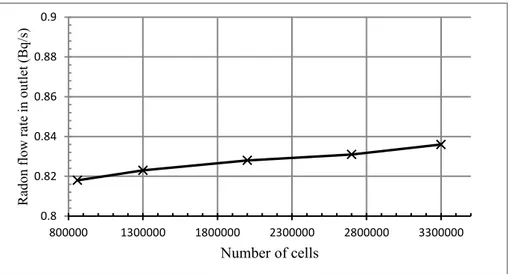
Figure 8. Average radon concentration for different mesh sizes ... 52
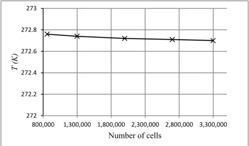
Figure 9. Average static temperature for different mesh sizes ... 52
Figure 10. Radon flow rate in the outlet for different mesh sizes ... 53
Figure 11. Radon concentration profile along a vertical line in the middle of the room for different mesh sizes ... 53
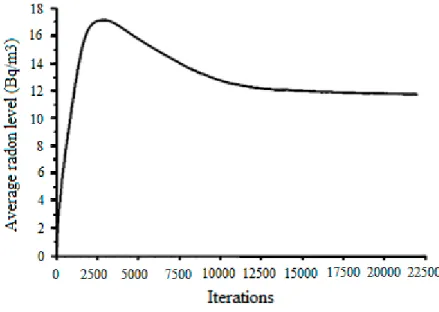
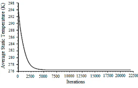
Figure 12. Average radon concentration versus iterations for the case N11 54 Figure 13. Average indoor static temperature versus iterations for the case indicated with N11 ... 55
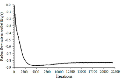
Figure 14. Radon flow rate in the outlet versus iterations for the case indicated with N11 ... 56
Figure 15. Residuals versus iterations for the case indicated with N11 ... 57
Figure 16. Radon level measurements versus ventilation rate ... 65
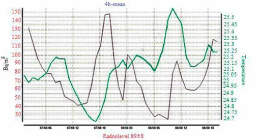
Figure 17. Radon level (green curve) and temperature (purple curve). ... 66
Figure 18. Radon level changes versus measurement height above the room floor ... 66
Figure 19. Average radon levels versus height (0-200 cm from the floor) ... 67
Figure 20. Average radon levels versus height (0-50 cm from the floor) ... 67
Figure 21. Average radon content for different air change rates at T = 21°C and RH = 40% ... 72
Figure 22. Radon concentration along a vertical line in the middle of the room for N3 (Ach = 0.5hr, T = 21°C, RH = 40%) ... 72
Figure 23. Radon content along a vertical line in the middle of the room for N12 (Ach = 0.25 hr-1, T = 21 °C, RH = 40%) ... 73
Figure 24. Position of two vertical planes in the middle of room for showing distribution of different quantities within the room... 73
Figure 25. Contours of radon concentration (Bqm-3) in two vertical planes in the middle of room for N3 (Ach=0.5 hr-1, T=21 °C, RH=40%) .. 74
Figure 27. Contours of radon concentration (Bqm-3) in two vertical planes in
the middle of room for N12 (Ach = 0.25 hr-1, T = 21 °C,
RH = 40%)... 75 Figure 28. Contours of air velocity (ms-1) in two vertical planes in the middle
of room for N12 (Ach = 0.25 hr-1, T = 21 °C, RH = 40%) ... 75
Figure 29. Average radon concentration in the room for different temperatures at Ach = 0.5 hr-1 and RH = 40% ... 76
Figure 30. Radon concentration along a vertical line in the middle of room for different temperatures (15 to 23°C) at Ach = 0.5 hr-1 and RH = 40%
... 77 Figure 31. Contours of radon concentration (Bqm-3) in two vertical planes in
the middle of room for N3 (Ach = 0.5 hr-1, T = 21 °C, RH = 40%)
... 78 Figure 32. Contours of radon concentration (Bqm-3) in two vertical planes in
the middle of room for N4 (Ach = 0.5 hr-1, T = 23 °C, RH = 40%)
... 78 Figure 33. Contours of radon concentration (Bqm-3) in two vertical planes in
the middle of room for N4 (Ach = 0.5 hr-1, T = 21 °C, RH = 40%)
... 80 Figure 34. Contours of radon concentration (Bqm-3) in two vertical planes in
the middle of room for N7 (Ach = 0.5 hr-1, T = 21 °C, RH = 50%)
List of Tables
Table 1. Physico-chemical characteristics of radon (Keith S, 2012) ... 2
Table 2. Features of the different numerical simulations in the publications7 Table 3. Annual radon average concentration in Västerås, Sweden ... 10
Table 4. Radon levels and remediation techniques (Radiological Protection Institute of Ireland, 2010) ... 12
Table 5. The operation ratings of the unit ... 20
Table 6. Date and time period of the measurements ... 22
Table 7. Velocity and turbulence intensity for different ventilation rates . 37 Table 8. Sizes of the building elements ... 40
Table 9. Different cases studied in this work ... 41
Table 10. Properties of the fluids (Lide, 2004) ... 42
Table 11. Properties of the solids (Lide, 2004) ... 42
Table 12. Mass fraction of water vapor for different relative humidity and temperatures ... 45
Table 13. Average radon concentration, average static temperature and radon flow rate in the outlet for different mesh sizes ... 51
Table 14. The heat rejection to outdoor environment through each outer surface, case N11 ... 60
Table 15. Measured indoor radon levels (Bqm-3) ... 64
Table 16. Radon level versus ventilation rate by measurement and analytic methods ... 68
Table 17. Dynamic simulation and energy calculation results ... 69
Table 18. Values used for life cycle cost analysis ... 70
Table 19. Ventilation system life cycle cost analysis ... 70
Table 20. Average radon content for different air change rates at T = 21 °C and RH = 40% ... 71
Table 21. Average radon concentration in the room for different temperatures at Ach=0.5 hr-1 and RH=40% ... 76
Table 22. Average radon concentration for different relative humidity at Ach = 0.5 hr-1 and T = 21 °C ... 79
Table 23. Indoor radon levels obtained by different methods ... 81
Table 24. Indoor radon for different heights above the floor ... 82 Table 25. The impacts of parameters on indoor radon level and distribution84
Nomenclature and abbreviations
Symbols
𝑨𝑨 Surface (m2)
𝑨𝑨𝑨𝑨 Radium activity (Bq kg-1)
𝑪𝑪 Radon activity concentration (Bq m-3)
Cf Skin friction
Cp Specific heat capacity (J kg-1 K-1)
D Effective diffusion coefficient (m2s−1)
Dh Hydraulic diameter (m)
𝑬𝑬 Radon exhalation rate(Bq𝑚𝑚−2ℎ−1)
f Radon emanation coefficient
𝑮𝑮 Radon generation rate (Bq m-3 s-1)
hc Heat transfer coefficient (W m-2 K-1)
𝒊𝒊 Interest rate (%)
I Turbulence intensity
𝑰𝑰𝒒𝒒 Net present value factor
𝒌𝒌 Thermal conductivity (W m-1 K-1)
K Turbulent kinetic energy (m2 s-2)
Mw Molecular weight
m Mass flow rate (kg s-1)
n Time in year unit
P Pressure (Pa)
q Annual energy cost escalation rate (%)
R Specific gas constant (J mol-1 K-1)
T Temperature (K)
𝑽𝑽 Volume (m3)
V Flow velocity vector (m s-1)
u, v, w Velocity components in x, y, and z coordinates (m s-1)
𝜼𝜼𝒕𝒕 Temperature efficiency
𝜼𝜼𝒘𝒘 Moisture efficiency
𝝀𝝀𝒗𝒗 Air change rate(h−1)
𝝆𝝆 Density (kg m-3)
𝝀𝝀𝑹𝑹𝑹𝑹 Radon decay constant (s-1 or h-1)
𝛆𝛆 Turbulent dissipation rate (m2 s-3)
µ Molecular viscosity (kg s-1 m-1)
𝝁𝝁𝒕𝒕 Turbulent viscosity (kg s-1 m-1)
ν Kinematic viscosity (m2 s-1)
𝜺𝜺 Porosity
Abbreviations
Ach
Air change rateASHRAE
American society of heating, refrigerating and air conditioning engineeringATD
Alpha track detectorCFD
Computational fluid dynamicsCHTC
Convective heat transfer coefficientCRM
Continuous radon monitorDHW
Domestic hot waterHVAC
Heating, ventilation and air conditioningHRV
Heat recovery ventilationHDD
Heat degree daysIAQ
Indoor air qualitykWh
Kilowatt-hourMF
Mass fractionPDE
Partial differential equationsRe
Reynolds numberRH
Relative humidityRn
Radon-222SST
Shear stress transport1 Introduction
Background
People in developed countries regularly spend more than 90 % of their time in confined and enclosed spaces, i.e. in homes, offices and vehicles. More than two thirds of this time is spent in residential buildings. Buildings act as a shelter and protect people from heat, cold, sunshine, noise, pollutants and other inconveniences. However, these shelters are not as safe as they could be, because they contain many indoor pollutants. Pollutants create indoor air quality (IAQ) problems which affect human health, productivity and com-fort. Unfortunately the variety and amount of pollutants are continuously increasing (Zhang Y. , 2004; WHO, 2009).
Radon is one of the major and most harmful indoor pollutants in many countries, such as the Scandinavian countries, the U.S., U.K., etc. Radon is estimated to account for more than 3,000 and 21,000 deaths annually from lung cancer in the UK and US respectively (Nilsson, 2006; EPA, 2008).
Sweden is one of the countries with the highest indoor radon concentra-tions in the world. This radon originates from uranium-rich soils and rocks such as alum-shale and uranium-rich granites (Sundal, Henriksen, Lauritzen, & Soldal, 2004).
Radon in the environment is present as a radioactive ground gas which exists in soil, water, air and in some natural gas. This radioactive gas mixes with air and is quickly diluted in the atmosphere. However, radon which enters enclosed spaces can accumulate and reach relatively high levels in some places, especially in buildings with insufficient ventilation (Malanca, Cassoni, Dallara, & Pessina, 1992).
General methods to control the levels of indoor pollutants are by source control, e.g. removal, replacement by alternative materials, sealing or dilu-tion, or by removal by ventilation and air cleaning. When the radon regulato-ry limit is set in the range of 600 Bq/m3 or less, ventilation becomes a
cost-effective and applicable method to dilute radon contamination and maintain IAQ in existing under-ventilated buildings (Radiological Protection Institute of Ireland, 2010), i.e. buildings with ventilation below the typical air ex-change requirement of 0.5 hr-1. Ventilation blows fresh outdoor air into the
room and reduces pollutant concentrations by mixing and dilution. However, building ventilation in turn leads to increased energy consumption in the
building sector. An optimal ventilation rate is therefore important for both people and governing authorities (in the case of housing associations).
Radon-222 (simply referred to as "radon") is a radioactive and inert gas which decays into alpha particles with a half-life of 3.82 days. This radioac-tive gas is colorless, odorless, tasteless, and is therefore undetectable without the use of specific instruments. It originates from decay chains of uranium and radium and is naturally occurring around the world. Radon in its gaseous form (at normal temperatures) is present throughout the earth's crust at dif-ferent concentrations which vary as a function of the nature of the soil. Some regions may therefore have serious issues with radon, as is the case in Swe-den, while others may have very limited or no concerns at all.
In standard conditions1, characteristics of radon are as shown in Table 1 (Keith S, 2012). Being a stable gas, radon is chemically neutral, and its half-life is long enough for it to accumulate in confined spaces. This radioactivity half-life also makes radon useful in the physical sciences as a natural tracer. (WHO, 2009).
Table 1. Physico-chemical characteristics of radon (Keith S, 2012) Density
(kgm-3) Diffusivity in Air (m2 s-1) Decay rate (s-1 ) Atomic weight (gmol-1)
9.73 1.1×10⁻⁵ 2.1×10⁻⁶ 222
Studies show that there is a direct link between breathing radon and lung cancer. Thus, radon is a significant contaminant and affects IAQ throughout the world. Radon is the main contributor to public exposure to radioactivity. In the United States, radon is the most important cause of lung cancer after cigarette smoking (EPA, 2008).
When radon accumulates in a room, up to 70 % of it decays into metal ions. These decay products are called radon progeny (daughters). Radon itself is an inert gas and does not carry health risks, while its progeny, alpha particles, Po214, Pb214, Bi214, and Po218 are harmful to the airways of the
hu-man respiratory system. These non-gaseous radon progeny, which settle on airways, are the main routes of exposure. Their ionizing power is 20 times greater than beta rays and gamma rays. Radioactive alpha particles are char-acterized by low permeability but high ionizing power (Dainius & Aloyzas, 2007).
Radon activity concentration is measured in the SI derived unit Bqm-3
(Becquerel per cubic meter). One Becquerel is the quantity of radioactive material that will produce one transformation in one second; 1 Bq is equiva-lent to 1 event of radiation emission per second. The Becquerel is thus a
measure of the activity rate (and not the energy) of radiation emission from a source.
The building sector accounts for almost 40 % of the world’s energy use, and exceeds the transportation sector in terms of carbon emissions (Zhang & Cooke, 2010). Most of the energy use in the sector is related to heating, ven-tilation and air conditioning, which together account for 55 % of the energy use in residential buildings (Zhang & Cooke, 2010). In Sweden for example, about 61 % of energy used in the building sector is used for space heating and domestic hot water (Swedish Energy Agancy, 2010). It is important from the energy conservation point of view that ventilation rates are not ex-cessive, but at the same time they should be sufficient to ensure good IAQ. Radon reduction strategies should also aim to consider problems related to radon sources and transport processes to be efficient and cost-effective. Strategies can include active and passive soil depressurization, barriers and membranes, sealing entry routes, sealing building material surfaces and ven-tilation of occupied spaces.
Sometimes a combination of all these strategies may be necessary, partic-ularly in buildings with highly elevated radon levels. This thesis focuses on ventilation strategy by using a heat recovery ventilation system and de-scribes how to simultaneously improve the complications related to energy use and indoor radon concentration.
Problem description and motivation
Global energy consumption, particularly in the building sector is growing, and the use of energy-efficient technologies in ventilation systems has an important role to play in energy savings and emissions reduction.
Reducing radon in residential buildings is a significant problem from the viewpoints of IAQ, adverse health effects and energy savings. Reducing radon by means of forced ventilation inevitably leads to higher energy use. Heat recovery ventilation (HRV) systems as an energy-efficient technology can recover energy in exhaust air that would otherwise escape, both reducing energy use and balancing indoor and outdoor pressure to reduce radon con-centration.
Earlier studies (Fournier, Groetz, & Jacob, 2005; Narula, Saini, Goyal, & Chauhan, 2009) in this field have focused on factors affecting radon distribu-tion in soil and its characteristics. Some very recent and concurrent studies (Chauhan, Joshi, & Agarwal, 2014; Kumar, Chauhan, & Sahoo, 2014), are focusing on the comparison of CFD simulation results of radon concentra-tion and exhalaconcentra-tion rates with experimental measurements indicating the importance of research on the indoor radon problem.
However, these studies do not explain how physical and environmental factors affect indoor radon concentration. The present study considers differ-ent indoor temperature and humidity conditions, vdiffer-entilation rates, and other possibly important parameters to determine their effects on indoor radon distribution and concentration.
HRV systems are a well-known technology in Europe and are used as en-ergy-efficient systems. A HRV system can provide the required indoor con-ditions in several ways. For instance, it can balance the pressure difference due to supply and exhaust with fans and thus control indoor radon level. This study intends to improve the research community’s understanding of the conditions and the extent to which HRV technology can be applicable and cost-effective for indoor radon control relative to other mitigation methods.
In this study I use computational fluid dynamics (CFD) and measurement techniques to show the influence of several parameters on indoor radon level in a detached house. CFD is used to simulate and estimate indoor radon con-centrations and dynamic simulation is employed to analyze energy use by means of a rotary heat exchanger installed in the house.
Aims and objectives
The main aim of this work is to investigate the influence of ventilation, in-door temperature and humidity on radon mitigation using measurement, dynamics and numerical simulation from the viewpoints of energy savings and indoor air radon quality.
The research questions are:
Is it possible to use CFD to simulate and predict indoor radon distribu-tion in residential buildings with and without HRV?
What is the indoor radon distribution suggested by the CFD results? Under what conditions is a HRV system economically appropriate for reducing indoor radon in residential buildings relative to other mitigation methods?
What is the relationship between indoor temperature, indoor humidity, position of the supply and exhaust air terminal devices, and indoor radon level and distribution?
Methods, limitations and research process
Methods:
In this study, dynamic and CFD simulation, measurement and analytical methods have been used.
Limitations:
In the work described in this thesis, several assumptions have been made for simplicity and to comply with computational limitations (a High Perfor-mance Computing facility was not available for this study). These limitations and assumptions have potential to be developed and modified in future stud-ies using other CFD methods and by considering more complicated build-ings or rooms. For instance, the effects of residents and their furnishbuild-ings, as well as the effect of non-ideal airtightness (leakages) in the building have been ignored in this work. Another assumption used throughout the thesis is that ventilation is provided by mechanical means (and with heat recovery) as opposed to other ventilation solutions. Assumptions have also been made regarding constant radon generation rate and outdoor conditions, as well as simplifications in the numerical modeling and intrinsic limitations of CFD techniques because of discretization and semi-empirical turbulence modeling methods.
Research process:
1. Investigating and gathering data on radon in recent years in the case study house.
2. Collecting new measurements with a continuous radon monitor in dif-ferent situations and under difdif-ferent temperature and relative humidity conditions.
3. Evaluating a heat recovery ventilation system. 4. Dynamic simulation using IDA 4.1 software.
5. CFD simulation using the ANSYS FLUENT 14 package.
Thesis outline
This thesis is broadly organized on two levels. The first level considers the role of a heat recovery ventilation system in energy saving and indoor radon control using life cycle cost to show its cost-effectiveness (Paper I). The second level considers indoor radon and effects of indoor air conditions in-cluding temperature, humidity and ventilation rate (papers II–IV).
The thesis comprises of six chapters and the contents are outlined as fol-lows:
Chapter 1 Introduction: background, problem description, motivation, objectives, thesis scope and outline.
Chapter 2 Literature review: review of heat recovery ventilation system, radon mitigation, radon transport mechanisms and modeling.
Chapter 3 Materials and Methodology: case study house, radon detec-tors, dynamics and CFD simulation packages.
Chapter 4 Numerical modeling procedure: discretization of radon transport equation, indoor radon modeling, boundaries, geometry and ma-terials.
Chapter 5 Results and discussion: results and discussion of radon meas-urement, dynamic simulation, economic analysis and numerical model-ing.
Chapter 6 Conclusion and future works: dynamic simulation and heat recovery analysis, numerical simulation and future works.
Summary of included papers
Paper I:
Paper I focuses on dynamic simulation and energy recovery calculations. The results confirm that using a heat recovery unit can meet energy saving and radon mitigation needs simultaneously. It is shown how a heat recovery ventilation system means that an increased outdoor air flow rate can be com-bined with a comparatively limited increase in the energy demand for space heating in order to dilute and lower indoor radon levels. Life cycle cost anal-ysis also indicates that a heat recovery ventilation system can be cost-effective.
Paper II:
This paper presents the first simple 3-D model to simulate radon generated from soil using CFD and the FLUENT software package. This work investi-gates the effects of ventilation rate, exhaust fan and supply fan on indoor radon. The results show that the effects of supply air terminal device location on radon level and distribution are distinguishable under different supply air flow rates. Compared to an exhaust fan, a supply fan has a greater impact on radon mitigation. Air leakages through doors and windows can have a simi-lar effect on indoor radon behavior to a supply fan. Of course this by no means a general conclusion, but an example from specific calculations on a particular type of residential building.
Paper III:
In this paper the effects of ventilation rates, temperature, humidity and pres-sure is investigated on indoor radon. Results of numerical studies indicated that changes of ventilation rate, indoor temperature and moisture by means of ventilation systems have significant effects on indoor radon content. Ven-tilation rate was inversely proportional to indoor radon concentration.
Mini-mum radon levels were estimated in the range of thermal comfort, i.e. at 21℃ and relative humidity between 50–70%.
The approach of this paper is similar to Paper II, but the case study house is modeled without soil section and using fine grids.
Paper IV:
This study uses an improvement over the model described in paper III. A heat recovery ventilation system unit was used to control the ventilation rate. As well as ventilation rate, this model considers the effects of indoor air temperature and relative humidity. The results from analytical solution, measurements and numerical simulation showed that air change rate had a significant effect on indoor radon concentration but indoor air temperature and moisture had little effect.
Overview:
This thesis used the K-ω turbulence model in ANSYS FLUENT 14.0 instead of the K-ε model in FLUENT 6.4 used in papers II–IV with the aim of im-proving the near wall treatment.
The dynamic simulations and calculations on heat recovery presented in Paper I are the same as the results presented in the main body of this thesis. Table 2 presents an overview of the different numerical simulations present-ed in papers II–IV and in the main body of this thesis.
Table 2. Features of the different numerical simulations in the publications Publication Geometry Model Kinds of air
conditions Turbulence and grid cells Paper II House
without partitions
Soil radon, Mixture of air and radon in species model
Exhaust and
sup-ply fans separately Turbulence k-ε model, 200,000 hexahedral cells Paper III All rooms Indoor radon, Mixture
of air, moisture and radon in species model
Temperature, Humidity, Pres-sure difference, Balanced ventila-tion Turbulence k-ε model 370,000 hexahedral cells
Paper IV All rooms Indoor radon, Mixture of air, moisture and radon in species model
Temperature, Humidity, Bal-anced ventilation Turbulence k-ε model 700,000 hexahedral cells Thesis One room Indoor radon, Mixture
of air, moisture and radon in species model
Temperature, Humidity, Ba-lanced ventilation Turbulence k-ω model 2,700,000 hexahedral cells
Contribution to knowledge
The literature survey reveals that there is little or no research available in the public domain regarding the analysis of the effect of heat recovery ventila-tion on indoor radon mitigaventila-tion using advanced CFD simulaventila-tions. With this in mind, the author’s efforts have focused on the development of models and methods of numerical simulation of indoor radon, as well as on the meas-urement of indoor radon, temperature and relative humidity with advanced equipment.
The author’s contribution to the knowledge in the area can be summarized as follows:
Development of CFD models for analyzing indoor radon concen-tration and distribution in one-family residences.
Analysis of IAQ focusing on indoor radon using the aforemen-tioned models. The application of a HRV system was considered in detail because of its capacity for controlling indoor radon con-centration as well as indoor temperature, pressure, moisture and ventilation rate. Displacement ventilation was assessed as a likely candidate for ventilation with regard to radon mitigation; the sim-ulation results indicate that the performance of such a system is likely to be dependent on the vertical position of its installation within the occupied zone.
It is important to note that the presented work is supported by three peer-reviewed journal publications and one peer-peer-reviewed conference paper.
2 Literature review
This chapter provides a review of the literature on previous relevant re-search: energy use and heat recovery ventilation system; ventilation and indoor radon mitigation; radon transport mechanisms and effects of environ-mental conditions; radon modeling methods.
Indoor radon levels, energy use and heat
recov-ery ventilation system
The World Health Organization recommends 100 Bqm-3 as a new indoor
radon action level (WHO, 2009). This value is currently 200 Bqm-3 in
Swe-den. Based on a recent radon survey in Sweden, 35 % of all monitored small houses and 28 % of apartments had radon levels that exceeded 200 Bqm-3
(Hjelte, Ronquist, & Ronnqvist, 2010).
Sweden has the second highest indoor radon levels among Scandinavian countries. Based on the radon risk map of a municipality in Sweden, about 70 % of Swedish surface (ground) has normal risk, with radon content of 10,000–50,000 Bqm-3 due to bedrocks and soil with low normal Uranium
content and average permeability (Dubois, 2005).
Around 300,000 buildings in Sweden include uranium-bearing building materials in the form of lightweight (blue) concrete which is used for inter-nal and exterinter-nal walls and sometimes in floor structures. The radon level in houses in which a substantial proportion of the building material consists of this type of concrete is elevated. Radon exhalation rate (E) from building materials in some Swedish buildings built between 1929 and 1975 is in the range 0.01 to 0.07 Bqm−2s−1 (Clavensjö & Åkerblom, 1994).
In a survey of radon measurement in 1,528 dwellings by Västerås munic-ipality produced with such material (Table 3), almost all homes were con-taminated with radon levels higher 200 Bqm-3, and more than 87 % had
radon levels in the range of 200–600 Bqm-3, in which the radon level can be
lowered using a heat recovery ventilation system. The minimum, maximum and average indoor radon levels found in this survey were 201; 4,650 and 405 Bq/m3 respectively.
These dwellings need mitigation measures in to lower the radon content at least to 100 Bqm-3. Increased ventilation is one possible general measure,
and this measure works regardless of whether the source of radon is the ground, building materials and/or domestic water.
Table 3. Annual radon average concentration in Västerås, Sweden (Taken from Västerås Municipality, 2009)
Indoor radon
(Bq/m3) Number of dwellings Percentage (%)
200–400 954 62.4
400–600 385 25.2
600–800 127 8.3
800–4650 62 4.1
Total 1528 100
When considering increased ventilation (i.e. a higher outdoor air flow rate) as a measure against radon it is important to be clear about two possible conditions:
1) The actual building has a lower total outdoor air flow rate than the requirements, with for example an average outdoor air flow rate lower than the minimum requirement in Sweden of 0.35 l / s m2
floor area on average. In this case increased ventilation will have a “double” advantage by both improving the IAQ in general and low-ering the radon content. The increased energy demand for space heating as a result of a higher outdoor air flow rate is not primarily the result of a measure against radon, but rather the result of a very general measure to increase the ventilation from a rate that is below minimum requirements.
2) The actual building has a total outdoor air flow rate in line with the requirements or higher. In this case increased ventilation will gener-ally cause “over-ventilation”, combined with an “unnecessary” in-creased energy demand for space heating. At the same time the ad-vantage with respect to lowered radon content still exists, but in this case increased ventilation is not as favorable as in condition 1. In this condition increased ventilation as a measure against radon faces very tough competition from other possible measures.
These two possible conditions are very important as a background to this thesis. However, the contents of this thesis do not focus specifically on sepa-rating the two possible conditions, but focus instead on the general influence of increased ventilation as a measure against radon.
With the very simplest assumption of steady-state conditions and complete mixing of the indoor air, it is well known that there is essentially a linear
relation between outdoor air flow rate and indoor radon concentration. This means that a doubling of outdoor air flow will only reduce indoor radon by about 50 %, e.g. from 600 Bq/m3 to 300 Bq/m3. It is important to be clear
about this general limitation regarding radon limitation by increased tion. This thesis includes simulations of the influence of increased ventila-tion where complete mixing is not assumed, but rather includes complex air flow patterns and radon transport within a building.
In Sweden, electricity use for domestic purposes (including household light-ing, electrical equipment and appliances) increased from about 9.2 to 20.7 TWh over the period of 1970–2010. This is because of the increase in the number of households, domestic appliances and electronic equipment and general increasing industrialization. Residential buildings and commercial premises used a total of 85 TWh for space heating and domestic hot water production in 2010. Of this, 42 % was used in detached houses, 32 % was used in apartment buildings and 26 % was used in commercial premises (Swedish Energy Agancy, 2010). In 2005, average domestic electricity use amounted to about 6,200 kWh per year in detached houses, and about 40 kWh per m² per year in apartment buildings, which for a 66 m² apartment means annual electricity use of 2,640 kWh per year (Swedish Energy Agancy, 2010).
The level of ventilation heat losses for a building relative to the total heat losses including transmission can vary widely between different buildings. In general, the ventilation heat losses as a fraction of the total will increase with the size of the building and with improved thermal insulation. For a large and very well insulated building, ventilation losses can be completely dominant. In low energy and airtight houses, as much as 50 % of the heat demand is often attributed to ventilation. This heat loss can be significantly reduced by using a heat recovery ventilation system, a good option among several other energy-efficient ventilation strategies for sustainable building concepts (Laverge & Janssens, 2012). This thesis focuses on the use of a heat exchanger to minimize ventilation losses. Other ways to utilize the heat in the exhaust air, e.g. with an exhaust air heat pump, are not investigated in this thesis.
Jokisolao (2003) and Lazzarin (1998) have compared various ventilation systems to show the advantages of heat recovery systems in cold climates (Jokisalo, Kurnitska, & Torkki, 2003; Lazzarin & Gasparella, 1998). Ener-gy-efficiency could be improved by up to 67 % compared to a traditional exhaust ventilation system by using a heat recovery system with a nominal temperature efficiency of 80% (Jokisalo, Kurnitska, & Torkki, 2003).
Ventilation effect and Indoor Radon Mitigation
The half-life of radon is only 3.82 days. Removing or sealing the radon source therefore greatly reduces the risk within a few weeks. In addition to removing or sealing the source, improving the ventilation rate of residential buildings can significantly reduce the radon level. The full impact of ventila-tion on radon levels is felt within hours. Generally, indoor radon concentra-tions can be diluted and reduced by increasing outdoor ventilation rates. The minimum indoor radon level in a sufficiently ventilated room is the same as the outdoor level (William, 1990; ASHRAE, 2001).
Since indoor radon cannot usually be eliminated by source control, venti-lation is used to dilute radon to an acceptable level.
Unlike a supply or exhaust fan ventilation system, a heat recovery ventila-tion system balances the indoor pressure in relaventila-tion to the soil and the out-doors.
Because of thermal gradients it is usual to have negative pressure indoors at floor level and positive pressure at roof level. This refers to a standard case with a significant temperature difference between indoors and outdoors (in winter) and a normal mechanical supply and exhaust ventilation system. The average pressure difference between indoors and outdoors can still be zero. Such a ventilation system mitigates indoor radon because of diluting and mixing effects (Handel, 2011).
Generally, the remediation techniques depend on the radon source, radon level and building type. Table 4 summarizes and lists remediation techniques with corresponding radon levels.
Table 4. Radon levels and remediation techniques (Radiological Protection Institute of Ireland, 2010)
Radon
levels (Bqm-3) Remediation techniques
C > 1000 Sub-floor depressurization (Radon sump) C < 600 Improved indoor ventilation
C = 400–500 Increased under-floor ventilation, sealing of cracks and gaps in the floor using polyethylene sheet and silicon glue (10 % effective)
Radon transport mechanisms and
environmen-tal conditions effects
As a gas, radon simply diffuses through the soil and other materials around the foundation of a home. Radon gas transportation from the soil into houses
results from physical and meteorological factors. Radon atoms escape through the larger air-filled pores within the soil and building materials, and a fraction reach the building-air interface before decaying and entering in-door air via the air flow. This transport occurs by molecular diffusion and forced flow (pressure induced flow), collectively referred to as diffusion and advection mechanisms. Radon transport into buildings therefore depends on convective flow from the soil pores through cracks in the floor and diffu-sion from building materials and soil. Convective flow depends on pressure differences across the substructure, and diffusion flow is dependent on the radium content, porosity, moisture, permeability and structure of the soil (Keskikuru, Kokotti, Lammi, & Kalliokoski, 2001).
Theoretical and mathematical relations indicate that diffusion and advec-tion mechanisms lead to radon transport. Both of these mechanisms are func-tions of physical and environmental condifunc-tions such as air flow, ventilation rate, indoor temperature and relative humidity, and pressure difference be-tween indoors and outdoors. In addition houses tend to operate under nega-tive pressure, meaning that the air pressure inside the home is lower than outside. This negative pressure results from the stack effect, the vacuum effect of exhaust fans, and a downwind effect caused by wind around a home (Loureiro, 1987; Spoel, 1998). The stack or chimney effect is due to the in-creased building temperature, which creates a rising vacuum cleaner effect which sucks out indoor air (Hoffmann, 1997).
Hoffmann (1997) also states that rainfall has negative impact on pressure, and a short time after rainfall indoor radon is increased because of the rising stack effect.
Previous studies have shown that physical and environmental condi-tions such as indoor and outdoor pressure difference, ventilation rate, tem-perature, moisture and meteorological factors have impacts on indoor ra-don. Outdoor temperature variations, storms and rainfalls are the most im-portant factors affecting mean radon levels (Milner, Dimitroulopoulou, & ApSimon, 2004).
Cozmuta (2003) showed that radon surface exhalation rate has a direct correlation with relative humidity in the range 30–70 %. Radon release rates from concrete increase linearly with moisture rates in this range. However, this reaches a maximum at 70 to 80 % humidity, after which transport rates decrease dramatically (Cozmuta, Van der Graff, & de Meiter, 2003).
Properties of radon such as diffusion coefficient, exhalation rate and ema-nation coefficient are affected by indoor air temperature and moisture. These relations are important when the diffusion mechanism is dominant in radon transport, and are explained in Appendix B.
2.3.1 Radon concentration equation in a ventilated room
In a ventilated room, the radon diffusion coefficient is disregarded and the radon transport equation or radon concentration in a building or room with volume V is described (Petropoulos & Simopoulos, 2001; Clavensjö & Åkerblom, 1994) as the following:
𝐶𝐶𝑖𝑖(𝑡𝑡) = 𝐶𝐶0𝑒𝑒−𝜆𝜆𝜆𝜆 +𝐸𝐸𝐸𝐸𝑉𝑉𝜆𝜆(1 − 𝑒𝑒−𝜆𝜆𝜆𝜆) (2.3)
where 𝐶𝐶𝑖𝑖 is the indoor radon concentration (𝐵𝐵𝐵𝐵𝑚𝑚−3) at time t(ℎ), 𝐶𝐶0 is
ei-ther the initial radon content at 𝑡𝑡 = 0 h or the outdoor radon concentration, 𝜆𝜆 is the total radon decay rate and ventilation rate (𝜆𝜆 = 𝜆𝜆𝑅𝑅𝑅𝑅+𝜆𝜆𝑉𝑉) in ℎ−1,
𝐸𝐸(𝐵𝐵𝐵𝐵𝑚𝑚−2ℎ−1) is the radon flux or radon exhalation rate from the soil or
building material, 𝐴𝐴 is the exhalation surface area (𝑚𝑚2) and 𝑉𝑉 is volume
(𝑚𝑚3) of the house or chamber.
At the steady state situation Equation 2.3 is reduced to:
𝐶𝐶𝑖𝑖=𝑉𝑉( 𝜆𝜆𝑅𝑅𝑅𝑅𝐸𝐸𝐸𝐸+𝜆𝜆𝑉𝑉) + 𝐶𝐶0 (2.4)
This equation also implies that the minimum value of the indoor radon con-centration is equal to the outdoor radon concon-centration.
When 𝐶𝐶0= 0 the indoor radon concentration level can be calculated as
(Clavensjö & Åkerblom, 1994):
𝐶𝐶𝑖𝑖=𝑉𝑉(𝜆𝜆𝑅𝑅𝑅𝑅𝐸𝐸𝐸𝐸+𝜆𝜆𝑣𝑣) (2.5)
where 𝐶𝐶(Bq𝑚𝑚−3) is the indoor radon at steady state, 𝐸𝐸(Bq𝑚𝑚−2ℎ−1) is the
radon exhalation rate, 𝐴𝐴(𝑚𝑚2) is the radon exhalation surface (in this study
the house floor), 𝑉𝑉(𝑚𝑚3) is the volume of the room, 𝜆𝜆
𝑅𝑅𝑅𝑅 is the radon decay
constant, and 𝜆𝜆𝑣𝑣(ℎ−1) is the air change rate in the house.
2.3.2 The effects of temperature and humidity on the pressure
field
In radon transport the dominant force is the pressure field, which is depend-ent on the advection mechanism of the indoor radon transport (Wang, F.; Ward, I C., 2002).
The balance between the condensation and the evaporation of water leads to a vapor pressure which depends on the temperature. At high temperatures air can hold more vapor than at low temperature (Sonntag, 1990). The relative humidity of the indoor air changes due to changes in the total pressure, and the pressure field influences the indoor radon concentration as
stated in the radon transport Equation 4.5. This effect is described in greater detail in Section 4.8.
Radon modeling methods
Numerical modeling using CFD is a powerful tool that can be used to esti-mate and predict indoor radon. These models can also help to design an improved cost-effective radon mitigation system. Numerical modeling of radon entry into buildings is a valuable and comparatively inexpensive tool for assessing the many factors controlling radon entry (Anderson, 2001).
Zhuo et al. (2000) used CFD to study the concentrations of radon in a ventilated room. They showed that the activity distribution of radon is uni-form except near the supply and exhaust locations. However, as the ventila-tion rate increases, the concentraventila-tions of radon fall and its activity distribu-tion becomes more complex due to the effect of turbulent flow. The simula-tion results of radon activity and distribusimula-tion were comparable with the ex-perimental results in a test room (Zhuo, Iida, Moriizum, & Takahashi, 2001). In an experimental work, Marley and Philips (Marley & Paul, 2001) claimed that mitigation of radon gas in buildings is mainly based on reduc-ing the pressure difference between the radon source and the indoor air. This study specifies the influence of mechanical ventilation systems in the control of radon level.
In a study by Wang and Ward, FLUENT, a commercial CFD package, was used to develop a model of multiple radon entry into a house. A grid-independency test, convergence behavior analysis and comparison with ana-lytical solutions were used for model verification. They also used an inter-model validation method to validate the strength of the inter-model, i.e. using the model to run a simulated case by an existing model (Wang, F.; Ward, I C., 2002).
Revzan (2008) developed a 3D steady state finite difference model for ra-don simulation. In this study, the simulation results were much lower than the measurement results, likely due to errors in the measurement of soil per-meability and variations in the perper-meability of the basement slab having a significant influence on the pressure field (Revzan, 2008).
The previous studies in this field have focused solely on factors affecting radon distribution in soil. These studies do not explain how physical and environmental factors affect indoor radon. However, the current study aims
to consider different indoor temperature and humidity conditions, ventilation rates and other possibly important parameters to determine their effects on indoor radon distribution and concentration.
3 Materials and Methodology
This chapter describes materials and methods used in this study. Materials include radon detectors, a heat recovery ventilation system, and the case study house. Employed methods are measurement, analytical analysis, dy-namic and CFD simulation tools.
The structure of this thesis is organized as follows:
Analysis of energy use and an air to air heat recovery ventilation unit using dynamic simulation software, IDA ICE, and analytical calculation.
Economic analysis of using the heat recovery unit.
CFD modeling and simulation to investigate the influence of some indoor air conditions and characteristics on indoor radon level and distribution.
Materials
3.1.1 Case study house
The case study house is a detached house in Stockholm that was built in 1970. This house provides suitable conditions for carrying out the objectives of this thesis because of the availability of a heat exchanger unit and radon data for several years, as well as agreement and assistance of the home own-er to test the indoor radon. This house is 2-storey structure and the volume of each storey is about 260 m3. The foundation of the building is located on
bedrock. The primary radon level was about 4,000 Bqm-3 on the first (ground
floor) storey, originating from the ground. The final radon level decreased to about 600 Bqm-3 after sealing part of the first storey and using a radon sump
in this storey (before installing the heat exchanger unit). Figure 1 shows the floor plan of the case study house.
Figure 1. Ground floor plan and zone divisions of the case study house
3.1.2 Heat recovery unit
Several different types of heat exchanger can be used in order to transfer heat from exhaust to supply air, but this study is limited to an application with a rotary heat exchanger. The rotor unit has a high efficiency and recov-ers up to 80 % of the heat and moisture from the air extracted from the house (Flexit, 2009). For a large majority of buildings, including normal residential buildings, moisture recovery is not needed. Perhaps 80 % of all problems and damage in buildings including sick building symptoms can be related to moisture. Ventilation has a very important function in limiting the accumula-tion of different pollutants and water vapor. The rotor material is an air per-meable and heat conductive material which picks up heat from the exhaust air and transfers it to the supplied air. The heat recovery wheel absorbs and transfers moisture (it is coated with a desiccant), thereby providing both sensible and latent energy recovery. Figure 2 shows the incoming and out-going air streams at the wheel.
Figure 2. Air flows through the rotary heat exchanger
The key factors when evaluating the performance of a rotary heat exchanger are temperature and humidity efficiency. These factors are usually specified by the manufacturer.
These factors are defined as:
Temperature efficiency 𝜂𝜂𝑡𝑡: 𝜂𝜂𝑡𝑡=𝑡𝑡𝑡𝑡1221−𝑡𝑡−𝑡𝑡1111 (3.1)
Moisture efficiency 𝜂𝜂𝑤𝑤: 𝜂𝜂𝑤𝑤=𝑤𝑤𝑤𝑤1221−𝑤𝑤−𝑤𝑤1111 (3.2)
where 𝑡𝑡 = temperature in °C, 𝑤𝑤 = water content of air in g/kg, 11 = fresh air condition before heat exchanger (outdoor), 12 = supply air condition after heat exchanger (indoor), 21 = extracted air condition before heat exchanger (indoor), 22 = exhaust air condition after heat exchanger (outdoor). Using Equation (3.1) and the measured temperatures, 𝑡𝑡11= −7.4, 𝑡𝑡12= 14.5 and
𝑡𝑡21= 22 °C , shows that these values are not always reached, as
demon-strated below:
𝜂𝜂𝑡𝑡= (14.5+7.4)/ (22+7.4) = 74.5%
In this study a mechanical ventilation system with an air-to-air heat ex-changer unit provides supply air to the building. This unit is a rotary energy recovery system, which recovers energy as both heat (sensible) and humidity (latent). Figure 3 shows the installed heat exchanger system inside the house.
Figure 3. The rotary heat exchanger installed in the building
The operation points of the unit can be determined from the diagram provid-ed by the manufacturer, consisting of a number of curves and axes. Given the ventilation rate, it is possible to find operation ratings of pressure, noise and fan electrical energy consumption (Paper I). These values are shown in Table 5.
Table 5. The operation ratings of the unit Specifications Operating rating 2 Fans power rating 2×35 W
Efficiency 74.5%
Ventilation rate 0.5 Ach (35 l/s)
Noise 50 dBA
3.1.3 Radon detectors
In this thesis both an Alpha Track Detector (ATD) and a Continuous Radon Monitor (CRM) are used to measure radon concentration. Unlike an ATD, which is passive and requires laboratory analysis to obtain the results, users can use CRM to detect radon instantly and anywhere with a personal com-puter.
The R2 CRM is an electronic device which is useful for measuring radon levels in the short and long term. This radon meter is used to identify indoor radon problems and the influence of physical and environmental factors such as ventilation effects and indoor conditions. The device also measures and logs indoor temperature and humidity so that any influence from the measur-ing environment can be determined. The CRM undergoes control irradiation at the Swedish Radiation Safety Authority (SSM) and gives very reliable