Design Automation Systems for Production Preparation : Applied on the Rotary Draw Bending Process
74
0
0
Full text
(2)
(3) THESIS FOR THE DEGREE OF LICENTIATE OF ENGINEERING. Design Automation Systems for Production Preparation Applied on the Rotary Draw Bending Process. JOEL JOHANSSON. Department of Mechanical Engineering SCHOOL OF ENGINEERING JÖNKÖPING UNIVERSITY Jönköping, Sweden. Department of Product and Production Development CHALMERS UNIVERSITY OF TECHNOLOGY Göteborg, Sweden 2008.
(4) Design Automation Systems for Production Preparation Applied on the Rotary Draw Bending Process Joel Johansson Department of Mechanical Engineering SCHOOL OF ENGINEERING JÖNKÖPING UNIVERSITY SE- 551 11 Jönköping, Sweden Joel.Johansson@jth.hj.se Copyright © Joel Johansson Research Series from Chalmers University of Technology Department of Product and Production Development ISSN 1652-9243 Report No. 33 Published and Distributed by Chalmers University of Technology Department of Product and Production Development SE – 412 96 Göteborg, Sweden Printed in Sweden by Chalmers Reproservice Göteborg, 2008.
(5) DESIGN AUTOMATION SYSTEMS FOR PRODUCTION PREPARATION APPLIED ON THE DRAW BENDING PROCESS. ABSTRACT Intensive competition on the global market puts great pressure on manufacturing companies to develop and produce products that meet requirements from customers and investors. One key factor in meeting these requirements is the efficiency of the product development and the production preparation process. Design automation is a powerful tool to increase efficiency in these two processes. The benefits of automating the production preparation process are shortened led-time, improved product performance, and ultimately decreased cost. Further, automation is beneficial as it increases the ability to adapt products to new product specifications with production preparations done in few or in a single step. During the automation process, knowledge about the production preparation process is collected and stored in central systems, thus allowing full control over the design of production equipments. Three main topics are addressed in this thesis: the flexibility of design automation systems, knowledge bases containing conflicting rules, and the automation of the finite element analysis process. These three topics are discussed in connection with the production preparation process of rotary draw bending. One conclusion drawn from the research is that it is possible to apply the concept of design automation to the production preparation process at different levels of automation depending on characteristics of the implemented knowledge. In order to make design automation systems as flexible as possible, the concept of object orientation should be adapted when building the knowledge base and when building the products geometrical representations. It is possible to automate the process of setting up, running, and interpreting finite element analyses to a great extent and making the automated finite element analysis process a part of the global design automation system.. Keywords: Design automation, Rotary draw bending, Knowledge Based Engineering (KBE), and Finite Element Analysis (FEA).. i.
(6) DESIGN AUTOMATION SYSTEMS FOR PRODUCTION PREPARATION APPLIED ON THE DRAW BENDING PROCESS. ii.
(7) DESIGN AUTOMATION SYSTEMS FOR PRODUCTION PREPARATION APPLIED ON THE DRAW BENDING PROCESS. ACKNOWLEDGEMENTS The research carried out through this thesis has been conducted in corporation between Jönköping University, Sapa Group, Faurecia, and Ekenäs Mekaniska Verkstad. I am very grateful for the funding by Sapa Group and the Knowledge Foundation (in Swedish KKstiftelsen). It has allowed me to concentrate on this specific research area that is close to my passion for mechanical engineering and computer programming. I also express my gratitude to Chalmers University of Technology, Department of Product and Production Development and Professor Rikard Söderberg, for kindly accepting me as a PhD student, making this work possible. I also express my gratitude to my supervisor, Staffan Sunnersjö, for his enthusiasm and belief in my ideas and guidance in my research efforts. I also thank Mikael Cederfeldt, Fredrik Elgh, and Roland Stolt for support and interesting discussions on the subject of design automation and research in general. Niclas Strömberg is also gratefully acknowledged: for doing FEM-calculations and also for guiding me when I performed FEM-calculations. Finally, I thank my family, especially my beloved wife, Synnöve Johansson, and my friends who have always stood by me, giving me their support and comfort. Jönköping, 2008 Joel Johansson. iii.
(8) DESIGN AUTOMATION SYSTEMS FOR PRODUCTION PREPARATION APPLIED ON THE DRAW BENDING PROCESS. iv.
(9) DESIGN AUTOMATION SYSTEMS FOR PRODUCTION PREPARATION APPLIED ON THE DRAW BENDING PROCESS. PUBLISHED PAPERS This licentiate thesis is based on the following published and appended papers: Paper A. –. J. Johansson and S. Sunnersjö (2006). Automated Design of Rotary Draw Bending Tools – An Approach Based on Generic CAD-Models Driven by Heuristic and Algorithmic Knowledge. EDMMP 2006, Wroclaw, Poland. Paper B. –. J. Johansson (2007). A Flexible Design Automation System for Toolsets for the Rotary Draw Bending of Aluminium Tubes. IDETC 2007, Nevada, USA. Paper C. –. J Johansson (2008). Manufacturability Analysis Using Integrated KBE, CAD and FEM. IDETC 2008, New York, USA. v.
(10) DESIGN AUTOMATION SYSTEMS FOR PRODUCTION PREPARATION APPLIED ON THE DRAW BENDING PROCESS. vi.
(11) DESIGN AUTOMATION SYSTEMS FOR PRODUCTION PREPARATION APPLIED ON THE DRAW BENDING PROCESS. TABLE OF CONTENTS Chapter 1 Introduction.................................................................................................. 1 1.1 The importance of design automation for production preparations............... 1 1.2 Realization of design automation .................................................................. 2 1.3 Research project and case of application....................................................... 2 1.4 Research questions......................................................................................... 3 1.5 Thesis outline................................................................................................. 3 Chapter 2 Research Method ......................................................................................... 5 2.1 Applying the research method ....................................................................... 6 Chapter 3 Frame of Reference...................................................................................... 9 3.1 Design automation ......................................................................................... 9 3.2 Draw bending – a short introduction ........................................................... 12 3.3 Existing systems for the automated design of draw bending toolsets ......... 14 3.4 dentified knowledge gaps ............................................................................ 17 Chapter 4 Design Automation Systems With a High Degree of Flexibility ............ 19 4.1 A modular structure of the knowledge base ................................................ 19 4.2 Adapting object orientation to the product structure ................................... 23 4.3 Stand-alone and CAD-integrated KBE-systems.......................................... 25 Chapter 5 Handling the situation When Multiple Types of Knowledge Coexist ... 29 5.1 Different sources of knowledge and meta-knowledge ................................ 29 5.2 Enabling knowledge adaptability ................................................................ 30 5.3 Evaluating the knowledge adaptability........................................................ 34 Chapter 6 Flexible Automation of the Finite Element Analysis Process ................ 39 6.1 Running an automated FEA-process within the global KBE-system.......... 39 6.2 Evaluating the automation of FEA .............................................................. 41 Chapter 7 Conclusions................................................................................................. 43 Chapter 8 Discussion and Future Work .................................................................... 45 8.1 How general are the methods presented in this thesis work? ...................... 45 8.2 Different research cycles ............................................................................. 45 8.3 Verification .................................................................................................. 47 8.4 Validation .................................................................................................... 48 8.5 Future work.................................................................................................. 48 Appendix A Implementation of the Knowledge Base .................................................. 49 Appendix B The Rotary Draw Bending Knowledge Base ........................................... 53 Appended Papers ............................................................................................................ 61. vii.
(12) DESIGN AUTOMATION SYSTEMS FOR PRODUCTION PREPARATION APPLIED ON THE DRAW BENDING PROCESS. viii.
(13) DESIGN AUTOMATION SYSTEMS FOR PRODUCTION PREPARATION APPLIED ON THE DRAW BENDING PROCESS. CHAPTER 1. INTRODUCTION This chapter provides an introduction to the thesis, defines the contents, and points out the research questions dealt with.. 1.1 The importance of design automation for production preparations Four critical factors for being competitive on the global market have been pointed out: low cost, short lead-time, improved product performance, and the possibility to adapt products to different costumer specifications (French, 1999). An automation of the production preparation process will shorten lead-time and make the adaptation of products to different specifications easier. An automation of production preparation would help improving product performance since it enables a common knowledge base, to which quality assurance issues can be targeted. The automation makes it possible to evaluate a big number of solutions. The ultimate reason for doing research on design automation is to avoid using human engineers from doing routine-like work and instead freeing them to do what they are really good at, creative thinking. Design automation for the production preparation will also help optimise products against production criteria since the production preparation is done in the same step. The design, evaluation and adjustment of toolsets are done automatically to new product specifications. When optimising the product, production criteria are hence available objectives. At the end, the automation of the production preparation process will make companies more competitive on the global market where constant, large economic pressure is the reality today.. 1.1.1 Cut lead-time The fact that shortened product development lead time is one of the main sources of competitive advantage has been realized since the 1980s (Smith, 1988, 1990). It continues to be important today because of global competition, fast changes in technologies and customer preferences, and the increasing development cost of new products. There are great possibilities to cut lead-time in the product development process through the automation of routine work. Although it cannot be said that the everyday work of an engineer is routine, the same data, formulas and rules are applied over and over again to adapt well-established concepts to new specifications. The know-how of this process is the special corporate competence or the special competence of one engineer in the product development team. This is especially true for variant products, a category to which toolsets for production equipments most often can be counted.. 1.
(14) INTRODUCTION. 1.1.2 Mass-customisation and variant rich products One of the critical factors for being competitive mentioned above is the possibility to adapt products to different customer specifications. This has led to mass customisation, defined as “producing goods and services to meet individual customer's needs with near mass production efficiency” (Kaplan and Haenlein, 2006). Design automation helps the development of mass-customized products since they have many variants and are a good automation target. Many of the variants can be achieved by configuring components, but many times more advanced tasks need to be completed. Examples include dimensioning using advanced formulas or verifying using simulations. Design automation supports the mass-customisation by automating these tasks.. 1.2 Realization of design automation A design automation system is a computerized system developed to support engineers in the design process. In order to make such systems available, theories from the field of artificial intelligence in computer science are adapted and utilized in the field of product development. Since design automation systems are intended to work within corporations, organizational aspects need to be considered as well. Automation has a strong potential to cut lead-time for such "routine" work mentioned above. Probably most engineers in that situation have already thought of, and implemented, some kind of automation, commonly by using spreadsheets, databases or algorithmic programs. In all those files, a lot of knowledge is stored. Since this knowledge is applied to the products developed by the company, it will be a part of the brand. Also, the knowledge stored in those files has probably been used for a long time and has thus evolved over time and been proven to work in practical applications. Hence, this knowledge is highly valuable for the corporation and should be captured and secured. Though captured, the knowledge still has to be usable. Further, although secure, it still has to be reachable. The systems built containing the corporate knowledge should be transparent and easy to understand for users and future developers. This means that it is easy for the user to understand not only how the system is built but also the knowledge itself. Thus, there are high requirements for documentation both on the system architecture and the knowledge it contains. In addition to this, Cederfeldt (2007) points out the following requirements that a design automation system should meet: low effort of developing, low level of investment, user readable and understandable knowledge, transparency, scalability, flexibility, longevity and ease of use.. 1.3 Research project and case of application The application of rotary draw bending of aluminium profiles has been the target of design automation. This application is beneficial because rotary draw bending is a common forming process in the industry. Adding knowledge on how to automate the design of toolsets for that process is of great importance itself. Further, the rotary draw bending process is representative of other metal forming processes, making them plausible applications for design automation using the same methods. There are some differences between regular tube bending and aluminium profile bending. Firstly, the components in the toolset are sometimes made from nylon. Secondly, tubes. 2.
(15) DESIGN AUTOMATION SYSTEMS FOR PRODUCTION PREPARATION APPLIED ON THE DRAW BENDING PROCESS. are only a subset of general profiles and, hence, commonly used heuristic rules will probably fail to predict the behaviour of the profile during and after the bend action. Thirdly, the material properties of aluminium are time dependent. The automation of the production process presented in this work is restricted to aluminium profiles with circular sections.. 1.4 Research questions The main research question for the work presented in this thesis has been: How to apply the concept of design automation to rotary draw bending toolsets for aluminum tubing? During the project this question has been divided into three sub questions: 1. How should design automation systems be built to allow a high degree of flexibility? 2. How should design automation systems be made able to handle the situation when multiple types of knowledge coexist for a single phenomenon? 3. How may design automation systems be built enabling automatic but also flexible finite element analysis of the rotary draw bending of aluminium tubing? When answering the research questions, further questions are raised, especially the question of how general the methods are. This question is addressed in the discussion chapter. In the thesis work, the proposals presented are viewed as hypotheses and described in the chapters along with the test implementations.. 1.5 Thesis outline In Chapter 2, the research method used to conduct the research carried out in this thesis is presented. Chapter 3 gives an introduction to the design automation, which is the research topic, but also to the rotary draw bending, which is the target of the experiments. In Chapter 4, how to build design automation systems with a high degree of flexibility is shown. Chapter 5 presents a method for how to model conflicting knowledge and how to solve situations of conflicts. In Chapter 6, how to automate the finite element analysis process as a local system in a global design automation system is illustrated. Chapter 7 concludes the research work, and a discussion is presented in Chapter 8. Appendix A contains two tables showing the implemented knowledge base. In Appendix B, the knowledge base developed for the design of toolsets for the rotary draw bending in order to conduct the tests is partly presented.. 3.
(16) INTRODUCTION. 4.
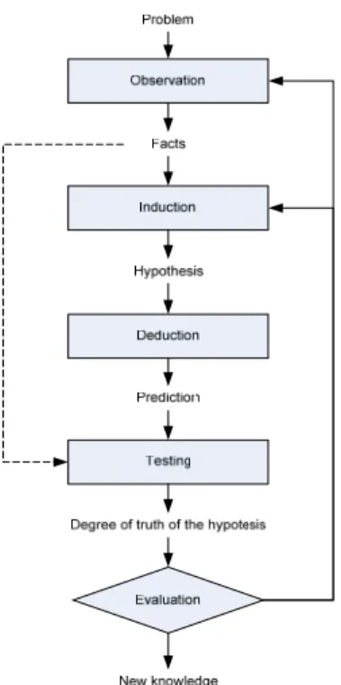
(17) DESIGN AUTOMATION SYSTEMS FOR PRODUCTION PREPARATION APPLIED ON THE DRAW BENDING PROCESS. CHAPTER 2. RESEARCH METHOD In this chapter, the applied research method used during the research project is described. It has been stated that research conducted on computer systems needs to be empirical (Simon, 1996). This is especially true for large computer systems, since they are too complex to build mathematical theories around without first building and observing them. A method to conduct empirical research is described by Groot (1969) as: Observation – supposition – expectation – testing – evaluation. This method has been adapted in the field of design and in the field of design automation. The adapted process is shown in Figure 1, and is taken from Roozenburg and Eekels (1995). This process starts with a problem definition, followed by observations resulting in a collection of facts. The facts are used to do an induction, resulting in a hypothesis. The hypothesis is use to deduce a prediction. To evaluate the level of truth in the hypothesis, the deduced prediction is tested against the real world. New knowledge is the result of the process.. Figure 1: The research method used is the one Roozenburg and Eekels have derived from Groot.. 5.
(18) RESEARCH METHOD. 2.1 Applying the research method Adapting the mentioned research method into the project resulted in the process shown in Figure 2. As seen, the first step is the problem definition, i.e. the selection of research topics. Then engineers are observed to see what activities, rules, and methods are suitable to be automated in the design process. Knowledge about how to create the knowledge base is then induced using the observations of the design process. The induced knowledge, together with background knowledge about design automation systems, is used to plan a design automation system for the selected product development subprocess. That step can be viewed as stating a hypothesis and deducing the system plan. The subsequent step is to test the system in order to establish some value of truth of the hypothesis. This is not a trivial step. How would a perfect test of a design automation system be designed and executed? One first thought might be to do an implementation and comparing system output to output from the observed product development subprocess. That test would show if the system calculates correctly compared to the original way of doing things. But it does not tell how well the system will perform in a big-scale solution within the organization and how it connects to other processes and systems. Another thought could be to let the engineers give their opinion. However, that often leads to user-interface discussions. To do the ultimate test, two parallel design processes, one traditional and one automated, should be initiated at the same time with the same people and the same environment to see the real performance of the automated system. This is of course not possible. Hence, we have to rely on the comparing outputs test. The test is intended to give insight into how good the system mimics the original process and answers the question of how true the hypothesis is. Finally, an evaluation of the process of observing and inducing is performed and reflected over to see if there are any mistakes or if anything could be done better. The documentation, evaluations, and reflections are added to the background knowledge of design automation systems and used in the next cycle of empirical research. The results are validated through close collaboration with industry partners throughout the research work and also through the research community via publications. Verification of a single system is based on experts’ acceptance of knowledge put into the system. Over time, a system is also verified through the acceptance of the design proposals generated by the system. In other words, if the engineers using the system seldom change the generated design proposals, it is verified. Otherwise, it is falsified.. 6.
(19) DESIGN AUTOMATION SYSTEMS FOR PRODUCTION PREPARATION APPLIED ON THE DRAW BENDING PROCESS. Figure 2: The applied research method was adapted from (Roozenburg and Eekels, 1995).. 7.
(20) RESEARCH METHOD. 8.
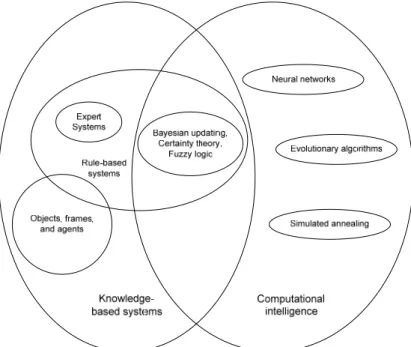
(21) DESIGN AUTOMATION SYSTEMS FOR PRODUCTION PREPARATION APPLIED ON THE DRAW BENDING PROCESS. CHAPTER 3. FRAME OF REFERENCE The aim of the presented research work has been to apply design automation to rotary draw bending. Hence, there are two supporting fields that need to be reviewed: design automation and draw bending. Design automation is the research topic of this thesis, and the rotary draw bending section is added to give the reader the necessary background information.. 3.1 Design automation Research done in the field of design automation is concerned with questions regarding how to automate the design process by means of computer implementations. Recent research in design automation has concerned the planning of design automation systems (Cederfeldt, 2007), how to make use of product information in the early phases of the product development process (Boart, 2007), the design process of functional products (Löfstrand, 2007), how to automate producibility aspects from a costing perspective (Elgh, 2007), and design for manufacturing (Sandberg, 2007). A design automation system affects many individuals in a product development company and organizational aspects need to be considered. Research concerning that problem is found in (Catic and Malmqvist, 2007), where knowledge based engineering is intended to be integrated into the product lifecycle management system.. 3.1.1 Artificial intelligence and Knowledge Based Systems Artificial intelligence can be defined as that branch of computer science concerned with the automation of intelligent behaviour. Creative thinking is not the scope of design automation. Rather, design automation involves the automation of routine work in order to free humans to do creative thinking. Anyhow, some of the methods found in artificial intelligence have proven to be successful when applying them to different routine-like tasks. One example is the design of kitchen layouts. The same types of components are used in every kitchen, and the layout is controlled by some few rules. But creating a computer implementation designing good kitchen layouts is a hard task using traditional procedural programming. To solve the problem, several solutions are generated according to implemented rules and searched using a search method. Another problem well suited for methods from the artificial intelligence is the diagnosis of systems through logical reasoning. For instance, in automating the diagnosis of why a car does not start, it is possible to define a rule base and search that for possible failures. In the two examples, knowledge is stored in a knowledge base searched by an inference engine; the complete system is called a knowledge-based system. The knowledge-based system is a subcategory of the more general category intelligent systems (see Figure 3) that is a result of the field of artificial intelligence. The knowledge-based systems can further be divided into sub sections including agent-based systems, expert systems, and fuzzy logic systems.. 9.
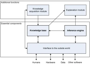
(22) FRAME OF REFERENCE. More about artificial intelligence in general and in practice is found in (Fulcher, 2006; Jones, 2003; Luger, 2005).. Figure 3: In (Hopgood, 2001), a categorization of the intelligent system software is done. The knowledge base systems category is a big share of the intelligent system domain and is broken down in several sub-domains.. 3.1.2 Knowledge Based Engineering Knowledge based engineering aims to automate engineering tasks by means of knowledge based systems. The fact that the concept of KBE has many definitions might be due to the wide area of the knowledge based systems and their many sub-categories. The definition of KBE adopted in this thesis work is the one stated by Stokes (Stokes and MOKA Consortium, 2001): “The use of advanced software techniques to capture and reuse product and process knowledge in an integrated way.” A general structure of a knowledge based system is shown in Figure 4, adapted from (Hopgood, 2001). As seen in Figure 4, the two keystones in a knowledge based engineering system are the knowledge base and the inference engine. The knowledge base is comprised of facilities to store knowledge in the sense of information in context. This means that structuralized data is stored with its context in a way that makes it possible for the inference engine to make use of it. Hence, the knowledge is separated from the routines (the inference engine) that make use of the knowledge. It is possible to define the knowledge base in different ways, different knowledge representations. The knowledge base must be machine-readable. This means that the knowledge base is designed to make the system able to automatically reason based on the knowledge. It would of course be highly beneficial if a machine-readable knowledgebase also was human-readable, which is far from common. In this thesis work, two knowledge bases are implemented, one containing rules and the other containing knowledge objects.. 10.
(23) DESIGN AUTOMATION SYSTEMS FOR PRODUCTION PREPARATION APPLIED ON THE DRAW BENDING PROCESS. Figure 4: The main components in a knowledge-based system are the knowledge base and the inference engine. Techniques for how to build the inference engine and how to represent the knowledge in the knowledge base are adapted from the field of artificial intelligence (Hopgood, 2001).. Furthermore, it is possible to search the knowledge base in different ways, search methods. In this thesis work, the forward chaining (kitchen example mentioned in the previous section) and the backward chaining (diagnosis example mentioned in the previous section) search methods are interesting and described in detail in Chapter 4.1.2. Further information on knowledge representation and inference engines in the scope of engineering is found in (Hopgood, 2001; Sriram, 1997). The following terms are used in this thesis in connection with KBE-systems: a triggered object is an object with all input parameters known, but with at least one output parameter unknown; a solved object is an object with all output parameters known; the conflict set is the collection of all triggered objects; and, to fire a rule is to execute, or evaluate a rule.. 3.1.3 Integrating knowledge for analysis applications Knowledge based engineering is about integrating knowledge. One specific type of integration interesting in the scope of this thesis is the finite element analysis integration. Some examples of knowledge based engineering systems exist where the finite element analysis process has been integrated. Sellgren (1999) developed a framework for simulation-driven design, in which simulation models were extracted based on the CADmodel relationships. Chapman and Pinfold described how to use KBE and FEA for the design automation of a car body (Chapman and Pinfold, 2001), and a system was presented by Hernández and Arjona, (2007) that automatically designs distribution transformers and that uses FEM automatically. The design process of different jet engine components has also been the subject for design automation using KBE (or KEE) integrated with FEA (Boart, 2007; Sandberg, 2007). The benefit of integrating the FEA to KBE-systems is that the natural synthesis and analysis process is captured (see further Chapter 6).. 11.
(24) FRAME OF REFERENCE. 3.2 Draw bending – a short introduction Since rotary draw bending is the application of the research project presented in this thesis, a short introduction to that subject is merited and given in this section. The nomenclature shown in Figure 5 is used. φ RΩ τ. θΔ. t. RΑ θΑ. Symbol. σy φ. r RΑ RΩ. θΑ θΔ θΩ Ε Μ. Description Material yield strength Tube outside diameter Tube mean radius Nominal centre line radius Centre line radius after spring back Nominal bending angle Angular spring back Final bending angle Young's modulus Necessary moment for making the bend. Symbol L t tmax tmin k=R/φ. β δc δco δci C. Description Feed preparation length Original wall thickness Maximal wall thickness after bending. Minimal wall thickness after bending. Bending factor Transition zones (see figure 31) Average shrinkage rate Shrinkage rate for outer semi-circle Shrinkage rate for inner semi-circle Average perimeter length. Figure 5: Nomenclature for design variables.. A rotary draw bending tool is usually built from five different main parts (components for applying boost pressure will not be addressed in this work). Three of these parts, form die, clamp die, and pressure or follower die, are necessary for making a bend. The two other parts, mandrel and wiper, are used when there is a risk of wrinkling and/or flattening. Some of those components come in different variants. In figure 6, a tool set-up is shown where a form die with insert and a flexible mandrel with regular pitch are used. When designing a toolset for rotary draw bending, a few typical problems arise. Circumferential decrease means that the tube diameter has a tendency to decrease. Wall thickness distortion means that the wall thickness on the inner side of the bend will be increased and decreased on the outer side. The wall thickness distortion displaces the section neutral axis affecting the feed preparation. When releasing the clamp after bending, elastic deformations in the material make the tube spring back both in radial and in angular direction.. 12.
(25) DESIGN AUTOMATION SYSTEMS FOR PRODUCTION PREPARATION APPLIED ON THE DRAW BENDING PROCESS. Clamp. Wiper Mandrel Form die Follower. Figure 6: A tool set-up for tube bending can contain up to five main components that exist in many variants.. The mentioned phenomena have been studied to varying extents, and a summary of studied literature is found in Table 1. When searching the literature (handbooks and scientific publications), it is clear that duplicates of rules for some of the phenomena exist. In Appendix B, the spring back and the wall thickness distortion are described in detail addressing heuristic, analytical, numerical and experimental rules and data for these two phenomena. Phenomenon Angular spring back. Heuristic rules. Analytical rules. (Cone, 2007). -. -. (Tang, 2000). Developed length. (Cone, 2007; Gillanders, 1994; Miller, 2003). (Tang, 2000). Radial spring back. -. (Abdel-Malek and Maropis, 1998; Gillanders, 1994; Miller, 2003). (Bradley, 2007; Cone, 2007; Gillanders, 1994; Miller, 2003). (Tang, 2000). Circumferential decrease. Wall thickness distortion. Table 1: Several works have been reviewed to find rules for designing rotary draw bending toolsets. Sometimes there exist multiple rules for a phenomenon.. 13.
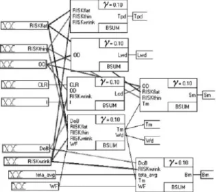
(26) FRAME OF REFERENCE. 3.3 Existing systems for the automated design of draw bending toolsets When it comes to the automation of the design of rotary draw bending toolsets, three different works have been found. They are briefly described and commented upon below.. 3.3.1 A rule-based system Abdel-Malek and Maropis (1998) performed the earliest of the research works found. In that work, theories from seamless design to manufacture (SDTM) were used to build a system for manufacturability analysis. That work presents an automated system for design-to-manufacture which can perform post-fabrication operations concerning bending and other processes. The system is a rule-based system integrated with a CAD-system (see Figure 7). The system enables the automatic design of the toolset assembly and generation of blue prints and NC code for appropriate mechanical parts. To make it possible to create and edit rules, a user interface was developed using three different types of “nodes” for displaying/retrieving data to/from the user, for performing calculations, and for branching to other “nodes”. The user interface was developed using the development tool Symbologic Adept, the rule base was developed using AutoLisp, and routines for the generation of drawings and NC-code were developed using the C language. Programmers skilled in AutoLisp and the C language can change the knowledge base in the described system, having competence in knowledge-based systems. Since the knowledge base is hard for humans to interpret, documentation is essential. The same is true for the in-house developed routines.. Figure 7: An overview of the system described in (Abdel-Malek and Maropis, 1998), from which the picture is taken.. 3.3.2 A goal-driven system Jin et al. (2001) performed the second work found describing the design automation of toolset for the rotary draw bending. It describes an object-oriented approach combined with an inference engine using a goal driven search mechanism. The objects created to build the knowledge base were collections of rules as they appear in a rule-based system. Semantic networks were used to describe the objects internal rule-set. The development language LEVEL5 OBJECTS was used to build the system. Figure 8 shows an example of the internal rule-set of an object for determining whether the final wall thickness will meet product requirements. Figure 9 shows how the inference mechanism in LEBEL5 OBJECTS connects different objects. 14.
(27) DESIGN AUTOMATION SYSTEMS FOR PRODUCTION PREPARATION APPLIED ON THE DRAW BENDING PROCESS. Figure 8: An object consisting of a set of rules described by a semantic net. The system is described in (Jin et al., 2001), from which the picture is taken.. Figure 9: The system developed by Jin et al was implemented using object oriented programming to build the knowledge base and user interfaces. The picture is taken from (Jin et al., 2001).. Since the declarative language LEVEL5 OBJECT was used to implement the knowledge, changes in the knowledge base can be done straight forward by a programmer skilled in that language. Since the objects can be cumbersome to read even to skilled knowledge engineers*, documentation is essential.. 3.3.3 A fuzzy logic system The third research work found describing a system for the automation of toolset design for the rotary draw bending was done by Strano (2005). That work presents a system using fuzzy logic to select correct tool components. The system is executed in two steps, where two different knowledge bases are used. In the first step, calculations are done to. *. An engineer who builds and maintains KBE-systems is often referred to as a knowledge engineer.. 15.
(28) FRAME OF REFERENCE. get values on variables to feed the knowledge base used in the second step. The second step is a fuzzy logic system. The approach when building the knowledge base for the fuzzy logic system was to transform all acquired knowledge into decision tables and in which selections are done using production rules (if … the … else). Figure 10 shows a section of the rule-block used to select appropriate type of mandrel. Figure 11 shows the structure of the fuzzy logic system. Further, a module for self-learning was added to make the system able to improve its selections.. Figure 10: A part of a rule-block implemented in the system developed by (Strano, 2005), from which the picture is taken.. Figure 11: An overview of the fuzzy logic system described by (Strano, 2005) , from which the picture is taken.. The presented system is hard to maintain since predicting what a change in the knowledge base would do is not a straightforward task. This is due to two facts. First, it is hard to make global changes when decision tables are used the way they are in the first knowledge base. Second, the knowledge stored in the fuzzy logic structure (that is actually doing the design proposal) and in the self-learning module is far from humanreadable. Making changes in these knowledge bases is very complicated.. 16.
(29) DESIGN AUTOMATION SYSTEMS FOR PRODUCTION PREPARATION APPLIED ON THE DRAW BENDING PROCESS. 3.4 dentified knowledge gaps It is clear that there are some knowledge gaps when reviewing the existing systems for the automation of the production preparation for rotary draw bending. The systems reviewed are hard to maintain due to their complex knowledge bases or due to the knowledge being transformed into something humans are not able to read. The systems are inflexible when adding or changing the knowledge because in such cases major parts of the system need to be changed. None of the systems are able to verify the generated design proposals. Additionally, it is found that multiple rules can be used for a single problem when reviewing the knowledge used by engineers in the observed development process. Further, the design proposals in the manual process are most often analyzed using the finite element method. This implies the development of methods for building design automation systems that have a high degree of flexibility, the ability to add redundant knowledge to the knowledge base, and the ability to analyze their own design proposals.. 17.
(30) FRAME OF REFERENCE. 18.
(31) DESIGN AUTOMATION SYSTEMS FOR PRODUCTION PREPARATION APPLIED ON THE DRAW BENDING PROCESS. CHAPTER 4. DESIGN AUTOMATION SYSTEMS WITH A HIGH DEGREE OF FLEXIBILITY Since it is of paramount importance for a design automation system to have a big degree of flexibility, this has been one of the research questions and is addressed in this chapter. Two ways of achieving flexibility are shown. One method is by applying the object orientation approach to the knowledge base. Another is by applying the object orientation to the product structure. Finally, guidelines are stated telling when to implement the knowledge using a CAD-integrated KBE-system and when to use a standalone KBE- system.. 4.1 A modular structure of the knowledge base To make a system truly flexible, all the parts building that system must be autonomous. Hence, to make the knowledge base truly flexible all the chunks of knowledge must also be autonomous. This implies the use of object orientation together with an inference engine.. 4.1.1 Knowledge objects Object-oriented programming offers the possibility to develop highly flexible programs, and a class of objects called knowledge objects* is proposed (see Figure 12). The least amount of information a knowledge object contains is a list of input parameters, a list of output parameters, and a method for process input parameters to output parameters. Other fields may be added to a knowledge object. Proposed additional fields are constraints, owner, categories, precision, and comments. Owner is used to trace who are responsible for the knowledge object and its method (the task it performs). The field categories can be used to sort knowledge objects into groups. Comments are used to add information usable for explanation extractions and debugging facilities. Finally, the list of constraints and the precision value is used to allow knowledge bases to contain conflicting knowledge objects (see further in Chapter 5.2.1). When implementing the knowledge objects, they should be defined in a way that makes them autonomous. Since the methods used to process information preferably are external software applications, the applications should be selected keeping in mind the list of requirements imposed on the design automation system: low effort of developing, user readable and understandable knowledge, longevity, and ease of use (Cederfeldt, 2007). The benefit of developing knowledge objects that are autonomous using common wide. *. Objects are closely related to frames. The difference is that a frame is passive in the sense that it doesn’t perform any tasks itself. An object, on the other hand, stores information about itself and performs certain tasks (Hopgood, 2001).. 19.
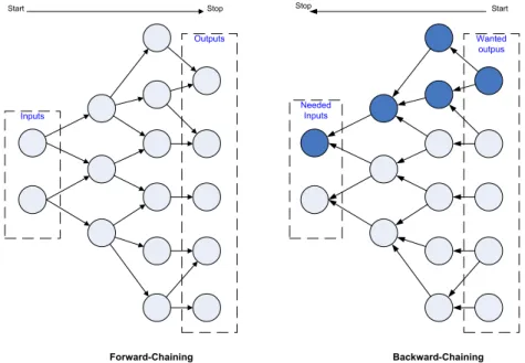
(32) DESIGN AUTOMATION SYSTEMS WITH A HIGH DEGREE OF FLEXIBILITY. spread applications as methods is that the knowledge can be used manually without the design automation system, and there will always be people skilled enough to use the very same knowledge the design automation system does. It makes the knowledge more human-readable (see section 3.1.2).. Figure 12: In the proposed method, the keystone to achieving a higher degree of flexibility in design automation systems is a class of objects called knowledge objects, with two lists of parameters and a method. A knowledge object may also have other fields, such as: constraints, comments, categories, precision value, and owner.. The anatomy of the knowledge used when designing toolsets for the rotary draw bending implies the use of knowledge objects. Several distinct tasks are identified and implemented as knowledge objects.. 4.1.2 Inference engine An inference engine is needed in order to use the knowledge stored in the knowledge base. The engine is used to arrange the knowledge in the knowledge base in an executable order. Two main types of search based inference engines exist: forward and backward-chaining (see Figure 13). A forward-chaining (also called data-driven) mechanism uses the information initially presented to fire all rules it can ever find. The method has two steps. In the first step, triggered rules are listed. In the second step, an appropriate rule from the triggered ones are selected and fired. After firing the selected rule, all triggered rules are listed again and so on, until no triggered rules are found. If knowledge objects are used to build the knowledge base, the inference engine searches for knowledge objects with all input parameters known and selects one of the found knowledge objects to execute the method defined in that knowledge object to calculate output parameters using the input parameters. When the method has run, the stock of known parameters is updated and a new search for executable knowledge objects is begun (see Figure 14). A backward-chaining mechanism (also called goal-driven) is fed with information of a final state. The mechanism then searches backward to see how to end up at that state. When knowledge objects are used, this means searching the parameter dependencies to see what information is needed to retrieve wanted output parameters. When using knowledge objects, the backward-chaining mechanism makes the system more effective. This is because executions of unnecessary methods are avoided. All the design parameters need to be calculated when designing toolsets for the rotary draw bending, implying the use of a forward-chaining mechanism. A key issue with inference engines is how to make the selection of an appropriate rule (or knowledge object) out of the found triggered ones. Different approaches exist: depth first, breadth first, and combinations of these two using heuristics. 20.
(33) DESIGN AUTOMATION SYSTEMS FOR PRODUCTION PREPARATION APPLIED ON THE DRAW BENDING PROCESS. In order to execute the knowledge objects, a connection layer is added to the inference engine. API-dependent routines are added in the connection layer making it possible to send and retrieve information from the external applications. Start. Stop. Stop. Outputs. Start. Wanted outpus. Needed Inputs. Inputs. Forward-Chaining. Backward-Chaining. Figure 13: Two main types of search-based inference engines exist: forward and backward-chaining. The first one uses the inputs to retrieve all possible data. The second one searches the knowledge base to see how to end up at a state presented to the system.. Figure 14: The collection of knowledge objects is solved using an inference engine that has a connection layer added where API-dependent functions are added in order to connect the external applications.. 21.
(34) DESIGN AUTOMATION SYSTEMS WITH A HIGH DEGREE OF FLEXIBILITY. 4.1.3 An event driven inference engine Event handling is available in today’s operating systems. And here it is proposed that the inference engine should make use of these advanced functions in the operative systems. That gives an event-based forward chaining search mechanism working as follows. When a parameter is changed, an event is raised in the system notifying that a change has occurred. This triggers an update of the conflict set. If there still are objects left in the conflict set, an object is selected according to implemented rules for selection in order to execute the object. When the object is executed, its output parameters are changed and the conflict set is updated, and so on (see Figure 15). The benefits of using events are the following: when implementing the inference engine, a lot of loop algorithms are avoided and when running the system the inference engine is triggered automatically on change, no extra button clicks are needed (unless functionalities for avoiding automatic updating are implemented and activated in the system). Update Conflict Set. Parameter Changed. Execute Knowledge Object. Figure 15: Using event handling when implementing an inference engine means that routines are run on changes. The change of a parameter triggers the system to update the conflict set. If it is not empty, a knowledge object will be fired causing parameters to change and so on. The loop is driven by parameter changes.. 4.1.4 Global and local automation To allow design automation systems to have a high degree of flexibility, the proposed method in this section is a modular knowledge representation interpreted by an inference engine. The modules themselves might be local design automation systems though. A knowledge module could, for instance, contain an algorithm for finding the shortest path using simulated annealing, and another module could connect to a configuration system getting a product structure. The global design automation system contains local design automation systems. It can be a semi-automatic system containing local isles of fully automated design automation systems connected by graphical user interfaces. The global system can also be a fully automated system containing isles of fully automated design automations systems that are fully integrated. This means that different levels of automation can be achieved and considerations have to be done to what extent and in what steps the design process should be automated and to what cost.. 22.
(35) DESIGN AUTOMATION SYSTEMS FOR PRODUCTION PREPARATION APPLIED ON THE DRAW BENDING PROCESS. 4.1.5 Evaluating the flexibility when using knowledge objects To evaluate the flexibility when using knowledge objects, an implementation was done. The implementation uses the class knowledge objects, as described in this chapter, and an event driven forward chaining inference engine as well. The production preparation for rotary draw bending was the application. Since additional features were added in connection with the other research questions, the implementation is described in Chapter 5.3.. 4.2 Adapting object orientation to the product structure The other way to achieve a higher degree of flexibility in the design automation system is to adapt the object orientation approach on the product structure. Doing so is especially beneficial when applying the concept of design automation systems to production toolsets. When it comes to modelling production tools using CAD integrated KBEsystems, it is hard to decide where to put the knowledge and the parameters/variables. To illustrate this, we can take one example. It is a toolset for rotary draw bending where some parameter might be needed in several or all of the components. In Figure 16, all five bending tool components are shown with associated parameters. It is clear that some parameters appear in several or all of the components. This indicates that there exist coupled relationships. In other words, changing the outer tube diameter will affect all components and trigger a sequence of dependent rules and calculations. An objectorientated view of the product is proposed to solve some issues. All components are viewed as objects with attributes (input parameters in this case). This is easily achieved in any parametric CAD-system. When using the object-oriented view of the components, the parameters are put on an appropriate level in the product structure. In the case of rotary draw bending toolsets, the parameters represented in several components are put at the top level in the product structure. All rules and calculations concerning these top-level parameters are also put at the top of the structure. When changing parameters at top-level, they are passed down to sub-level components, either using connections in the CAD-system or using macro programming (see further Chapter 3.2 in Appended Paper 1). Again, the key idea is to make all the parts in the system autonomous. Making all the components autonomous (in this case letting each component contain all necessary parameters for that component) will make the geometric product model more robust. It will then be easy to replace components without major failure.. 23.
(36) DESIGN AUTOMATION SYSTEMS WITH A HIGH DEGREE OF FLEXIBILITY. Clamp Die: Outer_tube_diameter Tool_height Grip_length. Wiper: Outer_tube_diameter Compensated_bend_radius Tool_height Grip_length. Form Die: Outer_tube_diameter Form_die_type Compensated_bend_radius Maximal_bend_angle Tool_height Grip_length. Mandrel: Outer_tube_diameter Wall_thickness Mandrel_type. Pressure/follower Die: Outer_tube_diameter Tool_height Follower_length. Figure 16: All parameters that a single component is associated to are viewed as attributes of objects. Since several parameters can be related to several components, parameter instances are made from the top-level of the product structure on which governing rules are applied.. 4.2.1 Evaluating the flexibility when adapting object orientation on the product structure In order to try the object-oriented approach on the product structure in a CAD-integrated KBE-system, a generic geometric model of a toolset for the rotary draw bending was created in CATIA and knowledge was added in CATIA/Knowledgeware. The main idea when building a design automation system for rotary draw bending in CATIA/Knowledgeware was to use the internal programming language to build methods executing external software applications to calculate different design variables (similar to the approach described in Chapter 4.1.1). The system contained methods for executing spread sheets to select correct types of components, material data, and bending machines. It also included methods for executing algorithmic programs to calculate developed length, minimal wall thickness after bending, angular spring back, and section modulus. Some factors were calculated using the internal functionalities in CATIA/Knowledgeware. 24.
(37) DESIGN AUTOMATION SYSTEMS FOR PRODUCTION PREPARATION APPLIED ON THE DRAW BENDING PROCESS. The knowledge implemented in the CATIA\Knowledgeware system was heuristic rules and rules analytically derived from fundamental physical laws as found in the literature. More details are found in Appended Paper 1. The knowledge base used in the applications is presented in the Appendix B. Two examples of output are shown in Figure 17. Parameter Outer_tube_diameter Tube_wall_thickness Wanted_bending_angle Section_modulus Tube_material Wanted_bendradius Results Mandrell_type Bending_moment Minimal_wall_thickness Developed_length. Example 1 45 mm 5 mm 180° 4.74 cm3 Sapa 6063-T4 80 mm Heuristic Analytic Plug N/A* 434 Nm 618Nm 3.9 mm 4.3mm 251mm 239mm. Example 2 60 mm 2 mm 180° 3.965 cm3 Sapa 6063-T4 80 mm Heuristic Regular Pitch 363 Nm 1.5 mm 251mm. Analytic N/A* 584Nm 1.6mm 228mm. Figure 17: Two examples of output from the system. Total time for set-up is a few minutes, where most of the time is spent typing in parameter values. In the heuristic rules, different factors are used when mandrel types are changed (1.3 for plug and 1.6 for mandrel). (*Was not implemented). 4.3 Stand-alone and CAD-integrated KBE-systems It is possible to implement the knowledge base in stand-alone KBE-systems or into CADintegrated KBE-systems. In Figure 18, an implementation using a CAD-integrated KBEsystem is shown. Figure 19 shows a KBE-system that is stand-alone and that connects to a CAD-system when a geometric representation is needed. When using a CAD-integrated KBE-system to implement the knowledge base, the rules will be listed in the model-tree among the different features. This can be valuable since it is easy to see what geometries the rules are connected to and the user will feel familiar with the user interface. But the knowledge base in such a system will be cumbersome to understand when the knowledge base contains a vast number of rules compared to the number of geometry features. This is especially true if many of the rules do not deal with geometry. If that is the case, a stand-alone KBE-system should be used. Another issue to consider is that when using a CAD-integrated KBE-system, the knowledge is bound to the CAD-system and the knowledge base will be hard to translate to other CAD-systems. In the stand-alone KBE-systems, the knowledge is managed and design proposals can be generated in native or neutral CAD-formats. It can be hard to. 25.
(38) DESIGN AUTOMATION SYSTEMS WITH A HIGH DEGREE OF FLEXIBILITY. implement a knowledge base containing mostly geometric relationships into a standalone KBE-system, though. In Figure 20, an overview of when to use a CAD-integrated or a stand-alone KBE-system is presented. Any external program. Excel-sheets. MathCAD-sheets. Embedded formulas. f(x)=ax2 +bx+c. Figure 18: To evaluate the flexibility when using a CAD-integrated KBE-system, CATIA was used to create a generic model of a toolset for the rotary draw bending. Knowledge was added to that model using CATIA\Knowledgeware.. MathCAD-sheets. π 2 δ 1 :=. 2 π. cos (α ) 2 k + 3 − 2 cos (α ) 2 k. 4 k + 1 + cos (α ). dα. 0. d 1−. δ1 + δ2 2. = 0.079 m. Figure 19: To evaluate the flexibility when a stand-alone KBE-system is employed, an inference engine was developed allowing the use of knowledge objects. The design proposals were communicated to the CAD-system using the API and CAD-templates.. 26.
(39) DESIGN AUTOMATION SYSTEMS FOR PRODUCTION PREPARATION APPLIED ON THE DRAW BENDING PROCESS. Geometric relations / Number of rules. 1 CAD-integrated KBE-systems proposed. Stand-alone KBE-systems proposed 0. 0. Geometry features / Number of rules. 1. Figure 20: A stand-alone KBE-system is proposed when the number of geometrical relationships compared to the total number of rules in the knowledge base is low and when the number of geometry features compared to the total number of rules is low. Otherwise, a CAD-integrated system is suitable for the implementation of the knowledge base.. 27.
(40) DESIGN AUTOMATION SYSTEMS WITH A HIGH DEGREE OF FLEXIBILITY. 28.
(41) DESIGN AUTOMATION SYSTEMS FOR PRODUCTION PREPARATION APPLIED ON THE DRAW BENDING PROCESS. CHAPTER 5. HANDLING THE SITUATION WHEN MULTIPLE TYPES OF KNOWLEDGE COEXIST Often there exist several sources of knowledge, and sometimes there are interferences between these sources. Developing methods for handling such situations will make the design automation systems more adaptable to different situations. In this chapter, the author shows how such interferences in a knowledge domain might occur and presents a proposal for how to solve these situations. Finally, the proposal is tested by implementation.. 5.1 Different sources of knowledge and meta-knowledge It is possible to calculate a single variable in different ways. Sometimes a heuristic rule can be used, or rules analytically derived from fundamentals. But it is also possible to do FEM-calculations or experiments to evaluate an interesting design variable. In addition to these four types of knowledge, an engineer also needs to have the capability to decide when to use what knowledge; this is called meta-knowledge or knowledge about knowledge. When more than one type of knowledge source is available in a knowledge base, the question of when to use what rule arises. In one state, the system may be executed in order to do a quotation calculation with only a small set of input parameters available. In the next step, detailed design is the purpose of running the system, with high accuracy as the main focus and with a larger set of input parameters available. Different kinds of knowledge are used in those different contexts, and implementing meta-knowledge would allow for flexible use of the system. A description of the different types of knowledge is presented below.. 5.1.1 Rules of thumb, heuristics Heuristics is generally found in different handbooks or company standards and is based on skilled engineers' experiences. Usually they are easy-to-use relationships that are valid for a small range in the design space. The heuristic rules seldom explain why things happen. The benefit of heuristics is that they have often proven to be correct enough and that they enable fast computer implementations. In reality, many design processes and design automation systems are built on this kind of knowledge (see Chapter 3.3).. 5.1.2 Knowledge analytically derived from fundamental laws of physics Rules analytically derived from fundamental laws of physics tend to be more complex than heuristics. However, they have the benefit of explaining why things happen and are more general. One benefit of analytical rules is that they are fast to execute when finally. 29.
(42) HANDLING THE SITUATION WHEN MULTIPLE TYPES OF KNOWLEDGE COEXIST. implemented in a computer system. Even though analytical rules are built on fundamental physical laws, they still are idealizations of complex problems.. 5.1.3 Finite element analysis There exist a number of numerical methods for solving different engineering problems. Probably the most common method is the finite element method (FEM). FEM can be used to solve many engineering problems. However, the results depend greatly on what mesh density and elements are used, what boundary conditions are prescribed, what material model is used, and what time step is set. Using FEM appropriately will give highly reliable data. The drawback is that, compared to heuristic and analytical knowledge, FEM is costly to use both in money, competence, and time. In addition, it does not explicitly answer the question of why things happen. The benefit is that FEM allows full control over the process so it is easy to scroll in time and space, doing sections and plotting different parameters. Worth mentioning in this context is that simulation-tools are comparable to instruments for measurements, i.e. they must be calibrated. This calibration is done via result feedback. Over time an accurate model will be developed.. 5.1.4 Experimental data Reality is the truth. Thus, making trial manufacturing will give reliable data. The drawback is that experiments are expensive, have a limited range and do not answer the question of why things happen. To make empirical data usable, experiment planning has to be done beforehand to isolate interesting parameters.. 5.2 Enabling knowledge adaptability In this section, a proposal is made on how to solve the situation when multiple types of knowledge coexist for a single phenomenon. The proposal is based on the extension of the knowledge objects and the usage of a common parameter list within the system.. 5.2.1 Extending the knowledge objects In Section 4.1.1, knowledge objects were introduced to represent the knowledge in the knowledge base. A list of constraints and a precision value needs to be added to the knowledge object class in order to make it possible to have multiple knowledge objects pointing to the same parameter in the knowledge base. The constraints tell when the knowledge object is applicable, and the precision value tells how good the knowledge outputs are. The precision value ranges between 0 and 1 and might be changed in the design space.. 5.2.2 A common parameter list Knowledge objects use external applications as methods. To pass information to the external applications, meta-data* is needed. That meta-data is stored in local instance *. Do not confuse with meta-knowledge.. 30.
(43) DESIGN AUTOMATION SYSTEMS FOR PRODUCTION PREPARATION APPLIED ON THE DRAW BENDING PROCESS. parameters within the knowledge objects. The calculated parameter values are stored in a global list of parameters. For example, in Figure 21, two different knowledge objects calculate a value for the parameter I as an output. Knowledge object number 1 uses application number 1 and needs some information on where to put the inputs and how to retrieve the outputs. Equally, knowledge object number 2 needs information on how to send and retrieve. That meta-data for the parameter is stored in the parameter instance in the knowledge object, while the parameter value is stored in the common parameter list.. A. P2. 2. G. High. H. B. I. Meta-data. A B C D E F G H I J K L. A. P1. 1. High. B. Meta-data. I J K. Figure 21: To make it possible to define multiple knowledge objects pointing to a single parameter, a common list of parameters is used to communicate values. However, each knowledge object carries instances of the parameters in the collection of input and output parameters. (Input parameters are to the left of the objects and outputs to the right.). The approach of using a common parameter list could be compared to a blackboardsystem with agents, see further Hopgood (2001) and Sriram (1997).. 5.2.3 Knowledge adaptability When a knowledge object writes a value to a parameter, the precision value of that knowledge object can be stored in the parameter in the common list. That will make a history of what precision a parameter value has. A rule is proposed saying that a knowledge object may only overwrite a parameter if its precision value is strictly bigger than the current precision value of that parameter in the common parameter list. The precision value of a knowledge object might change in different areas of the design space using formula. When using constraints together with precision values in the common list, the system will run in the following sequence:. 31.
(44) HANDLING THE SITUATION WHEN MULTIPLE TYPES OF KNOWLEDGE COEXIST. Do until the conflict set is empty: 1. List all triggered objects not violating any constraints, exclude solved objects. Sort the list by precision. 2. Execute the knowledge object with highest precision (“first come, first served” if several objects with the same precision exist). 3. Clear all output parameters in knowledge objects dependent on the outputs from the fired knowledge object. This can cause rules to fire more than once, but is done to make sure that the output with the highest precision is the final results.. 5.2.4 Solving rule conflicts Two different situations may occur when allowing the knowledge base to contain multiple knowledge objects for a single phenomenon. Let us say that there are four triggered objects at one stage in the conflict set. Three of the objects contain knowledge about phenomenon P1 and one object deals with phenomenon P2 (see Figure 22). Object number one and two have been assigned a high precision value, object number three a medium precision, and number four has a low precision value. The design parameters A to D and I are known, but J to N are unknown. The selected object to run in this situation will be object number one because it has the highest precision value and was added to the system before object number two. (Since objects one and two have the same precision value, the “first come, first served” rule is applied.) P1. I. 1. High. B C. P2. K L. 2. High. Precision. A. P1. I. 3. Med.. High. B. J. B A. A. N. P1. 1. I J. A. K. Low. J. B. K. A. M. P1. 1. N I. High. J. P1. K I. 3. Med. P1. 4. J K I. Low. B. 2. Selected object is executed. 1. Conflict set. L. High. B. I. 4. 2. B. K. P1. P2. D. M. D A. C. J. Precision. A. J K. 1. Conflict set. Represented phenomenon Represented Index. phenomenon P1. Index = Known parameter. 1. = Knowledge object. P1. 1. = Updated parameter = Unknown parameter. = Knowledge object. = Known parameter = Updated parameter = Unknown parameter. Figure 22: Objects do not overwrite values set by objects with precision values equal to or higher than their own precision value. (Input parameters are shown to the left of the objects and outputs to the right.). Situation one: The parameter I was calculated by a knowledge object assigned a precision value equal to or higher than the precision value of object number one. Since knowledge object number one is selected, it will be executed using the pre-defined method. Values for parameter I to K will be calculated. But since an object with a precision value equal to or higher than the precision value of the current object (object. 32.
(45) DESIGN AUTOMATION SYSTEMS FOR PRODUCTION PREPARATION APPLIED ON THE DRAW BENDING PROCESS. number one) set the I parameter, the value of parameter I will not be overwritten. Knowledge object number one will set only the parameters J and K in this situation. When updating the conflict set, knowledge objects 1, 3 and 4 will be considered solved since parameters I to K are known. The only object left in the conflict set is knowledge object number two. Situation two: The parameter I was calculated by a knowledge object assigned a precision value smaller than the precision value of object number one. Since knowledge object number one is selected, it will be executed using the pre-defined method. Values for parameters I to K will be calculated. Since an object with a precision value smaller than the precision value of the current object (object number one) set the I parameter, the value of parameter I will be overwritten. All the parameters I to K will be set by knowledge object number one in this situation. Since the parameter I is changed, all dependent parameters must be cleared. When searching the knowledge base, it is found that knowledge objects 5 and 6 have the parameter I as input (see Figure 23). This will make the parameters O to T invalidated since they were calculated using the value of the I parameter with a smaller precision. When invalidating the parameters O to T, knowledge objects number 5 and 6 will be considered triggered and put to conflict set. Knowledge objects 1, 3 and 4 are considered solved. At this stage, there are still four knowledge objects in the conflict set, so was the operation necessary? Yes, the value of the I parameter has a higher precision. Firing knowledge objects 5 and 6 using this better value will (probably) increase the precision of the values of the parameters O-T. C. P1. High P2. 2. A. P1. M. 3. P1. 4. P3. 5. P4. I. I A. K O. High. G. J. J. P1. 1. High. B. 6. 5. High. G. K. P4. I. 6. Med.. P1. 6. Med.. A. T. S. 2. Selected object is executed Index. 7. Med. P1. 1. High P1. 3. Dependent parameters are cleared. A. S T U V X I J. 3. Med. P1. Q R. 4. Low. B. K I J K I J K. 1. Conflict set. Index. 1. = Knowledge object. P1. P5. B. 1.Conflict set Represented phenomenon. P4. B. S. T. Represented phenomenon. A. Q R. N O P. K. P. F. J. O. Q R. Med.. I. P3. I. P. F Precision. J. Low. 5. High. H. K. B I. G. I. Med.. P3. L M. F. N. B A. I. K L. High. D. 2. High. D J. B C. I. 1. Precision. A. P2. 1. = Known parameter = Updated parameter = Unknown parameter. = Knowledge object. = Known parameter = Updated parameter = Unknown parameter. Figure 23: Objects do overwrite parameter values set by objects with precision value smaller than their own precision value. When that situation occurs, parameters dependent on the overwritten parameter are invalidated. (Input parameters are shown to the left of the objects and outputs to the right.). 33.
(46) HANDLING THE SITUATION WHEN MULTIPLE TYPES OF KNOWLEDGE COEXIST. 5.2.5 Two types of meta-knowledge Meta-knowledge can be implemented either in the inference engine or in the knowledge objects. The meta-knowledge implemented in the inference engine will be applied to every knowledge object. Take, for example, the rule saying that the knowledge object with the highest precision value should be selected to execute. That is a global rule and is suitable to be implemented in the inference engine. Other types of meta-knowledge are suitable to implement in the knowledge objects. It is, for example, often told that rules of thumbs are applicable only when the tube is “thin-walled”, often meaning that the wallfactor is greater than 10. Such meta-knowledge is best placed in the knowledge object itself. RA/φ The object is available in this region and put to conflict set when triggered. φ/t 10. Figure 24: When implementing meta-knowledge in the knowledge objects, the system will know when different objects are applicable. In this example, the wall-factor needs to be greater than 10 to make the knowledge object available (known as the thin-wall assumption).. 5.3 Evaluating the knowledge adaptability In order to evaluate the knowledge adaptability, a knowledge base with conflicting knowledge objects was developed and solved, and the product preparation of the rotary draw bending was targeted. To speed the process of defining the knowledge objects and to make an overview of the solve process, a graphical user interface was developed. The user interface contains two main controls, one tree view showing the knowledge objects and parameters, and one frame showing the conflict set (see Figure 25). Functions for developing and maintaining the knowledge base were also developed and added to the graphical user interface.. 34.
(47) DESIGN AUTOMATION SYSTEMS FOR PRODUCTION PREPARATION APPLIED ON THE DRAW BENDING PROCESS. Conflict set. Knowledge base. Figure 25: To make it easier to develop and maintain the knowledge base and to use the inference engine, a simple graphical user interface was developed. In the top picture, the knowledge base for the rotary draw bending is shown before running. In the bottom picture, the system has finished running.. 5.3.1 Defining objects and parameters The knowledge base implemented as a test is described in Appendix B. A parameter is viewed as an information carrier and in the common parameter list (see Figure 21) where. 35.
(48) HANDLING THE SITUATION WHEN MULTIPLE TYPES OF KNOWLEDGE COEXIST. there is no separation between input and output parameters. A sub-set of the common parameters implemented is listed in Table 4, found in the Appendix A. Some additional parameters were added in order to make file transfer possible when implementing the FEA (for further information, see Appended Paper 3). In Table 5, found in Appendix A, the complete collection of implemented knowledge objects is listed, with input parameters, output parameters and the method is used by the knowledge objects.. 5.3.2 Solving the knowledge base In order to evaluate the system using the knowledge base with conflicting knowledge, it was run twice with the same input parameters but with different knowledge objects active in the knowledge base. In the first run, all the knowledge objects were active. In the second run, the knowledge objects using experimentally developed data were suppressed. In Table 2, the first run is listed. The user provided the parameter values found at iteration zero, and they form the product specification. The conflict set is updated with executable knowledge objects from which one is selected to execute (written with italic letters in the table). In the next iteration, new parameter values are available and the conflict set is again updated (objects already available are not listed twice in the tables if not selected for execution). The execution sequence for the second run is listed in Table 3. That execution sequence is similar to when product specifications are given in a region of the design space where no experimentally developed knowledge is available. When comparing the two tables, it is clear that the use of experimentally developed knowledge is faster and that no FEMcalculations are generated to verify the design proposal. Iteration. Known parameters. Conflict set. 0. Wall_thickness=4mm Bending_radius=69mm Outside_tube_diameter=38mm Bending_angle=120deg Material_name=SAPA-6063T4 Wall_factor=9.5 Neutral_axis_displacement=0.751611 Yield_stress=68 Max_elongation=0.09 Young's_modulus=7000. Wall_factor Material Bend_factor Section_modulus. 1 2 3. 4 5 6 7 8 9 10 11 12. Final_radius=67.84 Developed_length=140.1 Average_perimeter=91.6 Min_wall_thickness=3.24 Max_wall_thickness=4.72 Final_angle=116.77 Elastic_Moment=314430 Plastic_Moment=0.81470 Total_Moment=314430 Section_Modulus=6588.75 Machine=Silfax 76 Mandrel=Plug. Neutral_axis_displacement Material Radial_springback_e Angular_springback_e Bending_moment_a Average_perimeter_e Wall_thickness_e Developed_length_e Developed_length_e Average_perimeter_e Wall_Thickness_e Angular_springback_e Bending_moment_a Section_modulus Machine_h Mandrel_selection. Table 2: The run procedure when knowledge objects containing empirical data were enabled.. 36.
(49) DESIGN AUTOMATION SYSTEMS FOR PRODUCTION PREPARATION APPLIED ON THE DRAW BENDING PROCESS. Iteration. Known parameters. Conflict set. 0. Wall_thickness=4mm Bending_radius=69mm Outside_tube_diameter=38mm Bending_angle=120deg Material_name=SAPA-6063T4. 1 2. Min_wall_thickness=3.13636 Wall_factor=9.5. 3. Min_wall_thickness=3.89474 Max_wall_thickness=4.32502 Neutral_axis_displacement=0.751611 Developed_length=143.201 Average_perimeter=94.1156 Yield_stress=68 Max_elongation=0.09 Young's_modulus=7000 Total_moment=314430 Final_radius=140.624 Final_angle=121.711 Bend_factor=1.81579. Wall_thickness_h Wall_factor Material Radial_spring_back_h Angular_spring_back_h Bend_factor Developed_length_h Section_modulus Wall_factor Wall_thickness_a Material Neutral_axis_displacement Average_perimeter_a Neutral_axis_displacement. 4 5 6 7 8 9 10 11. 12 13 14 15 16 17 18 19 20 21 22 23. Section_modulus=6588.75 Machine_name=Crippa Silfax 976 Mesh_size=3.31345 Material_model=Piecewise Analysis_type=Simple Mandrel=Plug FEA_Prepared_CAD_File=c:\CAD\... ToolSet_IsUpToDate=TRUE Meshed_CAD_file= c:\CAD\... FEA_IsUpToDate=TRUE CATIA_Bulk_Mesh=c:\TEMP\... Bulk_IsUpToDate=TRUE Mesh_Model=c:\FEM\... Mesh_IsUpToDate=TRUE FEA_File=c:\FEM\... FEA_File_IsUpToDate=TRUE Execution_Folder=c:\FEM\Run1\ FEA_Executed=TRUE Wall_thickness_Max=4.674 Wall_thickness_Min=3.514. Developed_length_a Average_perimeter_a Material Bending_moment_a Radial_spring_back_a Angular_spring_back_a Bend_factor Section_modulus Mesh_size_h Material_model Mandrel_selection FE_Model_type Machine_h Mesh_size_h Material_model FE_Model_type Mandrel_selection Geometry_Update Mesh_Model Mesh_Exports Mesh_Translation FEM_Control cards FEM_Calculation Wall_Thickness_n. Table 3: The run procedure when no knowledge objects containing empirical data were enabled.. 37.
(50) HANDLING THE SITUATION WHEN MULTIPLE TYPES OF KNOWLEDGE COEXIST. 38.
Figure

+7


Related documents
Material selection needed for urea injection arrangement, 3D printed model for visualization of the concept and integration of the model to next generation aftertreatment system
To confirm the validity of the minimum distance estimation function four different designs were created with arbitrary design parameters to see if the results from
Frequency, Diagnosis, Treatment, and Outcome of Gastrointestinal Disease in Granulomatosis with Polyangiitis and Microscopic Polyangiitis.. Per Eriksson, Mårten Segelmark and
För att råda bot på detta hinder har dock denna lärare en till synes lättsam och oproblematisk inställning då denne menar att det handlar om att hitta nya
Visualisation, Transparency, CSCW, PD, Ubiquitous Computing, Ethnography, Ethnomethodology, Interaction Design, Large-Scale Event, Tasks, Resources, The Bank of Tasks, The
Table 1: Definition and objective of five manufacturing system types, divided into the categories centralized and distributed systems. Kuras 2004), and the effect on SoSE...32
De intervjuade lärarna var eniga om att tidig insatser är en förutsättning för en god läsutveckling och även dokumentationen av elevens utveckling är av vikt för att undvika
The aim of this study was to develop a model using the NIR spectra of solid wood chips in order to predict their chemical properties such as lignin and moisture content and
