SimArch 2
Implementation and demonstration
of the SimArch architecture
ViP publication 2016-2
Authors
Anders Andersson, VTI
Jonas Andersson Hultgren, VTI
Rickard Leandertz, HiQ
Martin Johansson, Pitch Technologies
Steve Betnér, Pitch Technologies
Ola Jakobson, Volvo Car Corporation
ViP publication 2016-2
SimArch 2
Implementation and demonstration of the SimArch
architecture
Authors
Anders Andersson, VTI
Jonas Andersson Hultgren, VTI
Rickard Leandertz, HiQ
Martin Johansson, Pitch Technologies
Steve Betnér, Pitch Technologies
Ola Jakobson, Volvo Car Corporation
Fredrik Rolff, Volvo Car Corporation
Cover picture: Anders Andersson, VTI (modified from Martin Fischer) Reg. No., VTI: 2012/0206-25
Preface
The SimArch 2 - Implement and demonstrate the SimArch architecture project has been a
collaboration between HiQ, Pitch Technologies, the Swedish National Road and Transport Research Institute (VTI), and Volvo Car Corporation (VCC) within the competence centre ViP Driving
Simulation Centre (www.vipsimulation.se).
The main focus of the SimArch 2 project was to design and implement a distributed simulation architecture with the ambition to make it easier to transfer simulation studies between different simulator facilities and also create an environment where several simulators can be used together. Simulator facilities considered here range from consumer desktop computers to a high-fidelity driving simulator with Hardware-In-the-Loop systems close to a complete vehicle.
The project has been financially supported by the competence centre ViP, i.e. by ViP partners and the Swedish Governmental Agency for Innovation Systems (VINNOVA).
The software developed in the project is available at ViP common software platform ViPForge, https://www.vipforge.se/. Contact the ViP Forge administrator at VTI.
There have been numerous people involved in the SimArch 2 project during meetings and discussions but the main participants in the project have been:
Rickard Leandertz and Magnus Johansson from HiQ.
Martin Johansson and Steve Betnér from Pitch Technologies.
Anders Andersson (project manager), Jonas Andersson Hultgren, and Erik Olsson from VTI. Ola Jakobson and Fredrik Rolff from VCC.
The authors would like to give special thanks to Martin Fischer for his extensive work on the project application, to Joakim Hellström for assisting with network issues, and to Bruno Augusto for assisting with technical details and support regarding the moving base simulator Sim IV at VTI. The authors would also like to thank everyone who participated during the demonstrations, showing interest in the developed distributed simulation architecture.
Linköping, July 2016
Quality review
Peer review was performed on 14 September 2016 by Richard Romano, Leeds University and on 9 November 2016 by Martin Fischer, Deutsches Zentrum für Luft- und Raumfahrt (DLR). Anders Andersson has made alterations to the final manuscript of the report. The ViP Director Lena Nilsson examined and approved the report for publication on 12 December 2016.
Table of contents
Executive summary ...9 1. Introduction ...11 2. Software architecture ...12 2.1. User needs ...12 2.2. Session Control ...13 2.2.1. Simulation states ...14 2.3. Environment Simulator ...14 2.4. Driving Simulator ...15 2.5. Vehicle Simulator ...152.6. Interfaces and communication ...15
2.6.1. Runtime phases ...19
2.6.2. HLA workflow and tools ...20
3. Hardware platforms ...24
3.1. VTI driving simulators ...24
3.2. VCC HiL simulator ...25
4. Results ...26
4.1. Time measures ...26
4.2. Platform flexibility and scalability ...27
4.2.1. Connecting the VCC HiL simulator and HLA ...28
4.3. Demonstrations ...29 4.3.1. Demonstration in Gothenburg ...29 4.3.2. Demonstration in Linköping ...30 5. Conclusions ...32 5.1. Future Work ...32 References ...35
Appendix A – Conceptual model...37
Appendix B – Federation Agreement ...45
Appendix C – Minimum requirements for federates ...57
Abbreviations
ACC Adapted Cruise Control
DDM Data Distribution Management
DOF Degree of Freedom
DS Driving Simulator
DSEEP Distributed Simulation Engineering and Execution Process (a standard)
ECU Electronic Control Unit
EEG Electroencephalogram
ES Environment Simulator
ESC Electronic Stability Control
FOM Federation Object Model
HiL Hardware-in-the-Loop
HLA High-Level Architecture
IEEE Institute of Electrical and Electronics Engineers
OpenDRIVE Open format specification to describe the logic of a road network
RPM Revolutions Per Minute
RTI Runtime infrastructure
RTT Round-Trip Time
SC Session Control
SPA Scalable Product Architecture
UN User Need
VCC Volvo Car Corporation
VISIR Visual Simulation of Road or Railway
VS Vehicle Simulator
List of figures
Figure 1. Schematic view of the connections between SC, ES, DS, and VS with inter-connections. .. 12
Figure 2. Finite state machine used in simulation entities. ... 14
Figure 3. Objects used within the federation for communication between federates. ... 16
Figure 4. Objects used within a federation for management of a simulation. ... 17
Figure 5. Interactions that could be sent within a simulator environment during a simulation... 17
Figure 6. Interactions that could be sent within the federation for controlling the simulation. ... 18
Figure 7. Federation management during pre-runtime and runtime. ... 19
Figure 8. Pitch Visual OMT and Pitch Developer Studio workflow. ... 20
Figure 9. Example code from vehicleupdatelistener.cpp used in Session Control. ... 22
Figure 10. Modifications (shown in red) done to CORE at VTI to adapt to the SimArch architecture. Classes pictured under entities are examples of existing classes but is not a complete list. ... 22
Figure 11. Moving base simulator Sim III at VTI in Linköping to the left and the moving base simulator Sim IV at VTI in Gothenburg to the right ... 24
Figure 12. The VCC HiL-simulator including the three separate units for HiL-simulation and driver interface ... 25
Figure 13. RTT measure within local network from server at VTI in Linköping at different simulators ... 26
Figure 14. Simulator configuration (demonstration set-up) used in Gothenburg 12 November 2015 .. 29
Figure 15. Simulator configuration (demonstration set-up) used in Linköping 9 December 2015. ... 30
Figure 16. Pictures taken during the demonstration in Linköping showing the simulators Sim II and Sim III and a desktop simulator running in the same simulation environment. ... 31
List of tables
Table 1. A view of some of the generated files used by Session Control. ... 21 Table 2. The major distributed configurations tested during evaluation of the platform. ... 27 Table 3. Call rate and callback rate per federate during simulation. ... 28
SimArch 2 - Implementation and demonstration of the SimArch architecture
by Anders Andersson1, Jonas Andersson Hultgren1, Rickard Leandertz2, Martin Johansson3, Steve Betnér3, Ola Jakobson4 and Fredrik Rolff4
1Swedish National Road and Transport Research Institute (VTI), 2HiQ, 3Pitch Technologies, 4Volvo Car Corporation (VCC)
Executive summary
Complexity in modern vehicles consists of an increasingly large multitude of components that operate together. While functional verification of individual components is important, it is also important to test systems of interacting components within a driving environment, both from a functional
perspective and from a driver perspective. One proven way for testing is vehicle simulators and in the reported work the main goals have been to increase flexibility and scalability by introducing a
distributed driving simulator platform. As an example, consider a workflow where a developer can easily go from a desktop simulation to an intermediate driving simulator and further to a high-fidelity driving simulator with Hardware-In-the-Loop systems close to a complete vehicle.
To support this, a distributed simulation architecture was designed and implemented, based on user needs defined in a previous project which divides a driving simulator environment into four major entities with well-defined interfaces. These entities are Session Control, Environment Simulator, Driving Simulator, and Vehicle simulator. High Level Architecture (HLA) Evolved, an IEEE (Institute of Electrical and Electronics Engineers) standard, was chosen as the standard for communication. HLA Evolved is based on a publish-subscribe architecture, and is commonly used for distributed simulations. The entities and the communication topology are described in detail in the report. The evaluation of the distributed simulation architecture focused on flexibility and scalability, and on timing performance. Results show that the implemented distributed simulation architecture increased flexibility and scalability, compared to the non-modified architecture, as several distributed set-ups were tested successfully. However, distributed simulation has an inherent communication latency due to packaging and sending of data between entities. The communication latency was estimated to be one millisecond. This latency effect needs to be considered for a distributed simulation, especially if the communication between the Driving Simulator and the Vehicle Simulator is sensitive to such delays. During evaluations of the distributed simulation architecture, the Driving Simulator and the Vehicle Simulator were always located at one site in a low latency configuration. Thus, further investigations of the resulting communication delays between a Driving Simulator and a Vehicle Simulator at different physical locations are necessary.
Two demonstrations, open for anyone with an interest in the distributed simulation architecture, were performed, one in Gothenburg and one in Linköping. During the demonstrations, the distributed simulation architecture was shown where participants could freely test a distributed simulation set-up including the VCC Hardware-In-The-Loop simulator and three of VTI’s moving base simulators.
1.
Introduction
Modern vehicles are complex systems consisting of an increasingly large multitude of electrical and mechanical components that operate together. While functional verification on individual components is important, it is also important to test systems of components within a driving environment, both from a functional perspective and from a driver perspective. One proven way for testing is using driving simulators. In this work, the main goal has been to increase flexibility and scalability of a simulation platform for driving simulators. The flexibility of a simulation platform is defined as how easy it is to transfer a driving simulator experiment from one simulator platform to another. The scalability of a simulation platform is defined as how easy it is to add more actors to the simulation environment, where an actor can be a driver in a driving simulator or an autonomous software vehicle. To achieve increased flexibility and scalability a distributed driving simulator platform has been designed and implemented. Here, a distributed modular platform enables executing the whole system on one computer or running a simulation using hardware and software at geographically different locations, or set-ups in-between. Since the simulator platform can execute on different platforms it is also possible to execute the same experiment on different driving simulators without major
adaptations. As an example, consider a workflow where a developer can easily go from a desktop simulation to an intermediate driving simulator or a high-fidelity driving simulator with Hardware-in-the-Loop (HiL) systems close to the ones installed in the final vehicle. In such a workflow, the complexity of the platform needs to be low for both developers and users so that creating simulator studies requires a small effort, but if managed, the benefit is fast testing procedures. Another benefit of a modular structure is that with well-defined interfaces a developer can focus on single modules at a time and may consider the rest of the system as a black box.
The main question to investigate is if enough fidelity is obtained within a distributed simulator
platform so that simulation results can be trusted. A known problem with a distributed simulator set-up is time delays introduced by the distance between different sites. The effects of the time delays also affect different parts of the simulation differently, e.g. updating environment objects is expected to have softer timing requirements than the vehicle dynamics feedback. An investigation where transport delays can cause degraded performance and even unstable behaviour can be found in Allen and DiMarco (1984). To evaluate the fidelity of such a simulator platform an actual implementation needs to be realized since prototype implementations only give preliminary performance results.
The goal of this project was to implement and test a fully functional modular distributed simulator platform, which was initially designed in an earlier project where a first prototype (SimArch) was also implemented (Vinter, 2010). The constructed distributed simulator platform (SimArch2) includes different driving simulators and HiL environments, and increased scalability and flexibility have been demonstrated during several demonstrations. It has also been shown that studies can be moved between simulators supporting SimArch.
This report is an extension to the conference paper presented at the Driving Simulation Conference & Exhibition in Tübingen 2015 (Andersson et al., 2015). In section 2 the software architecture is presented. In section 3 the used hardware facilities that have been integrated with SimArch are presented, and in section 4 some results from preliminary testing are shown. Section 5 presents conclusions, and the Appendices contain contracts used within the simulator platform and a user’s guide. Software produced during this project is available for ViP partners at ViPForge1 and it is possible to run a simulation even though the development tools have been returned to Pitch Technologies.
1 https://www.vipforge.se/
2.
Software architecture
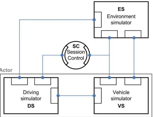
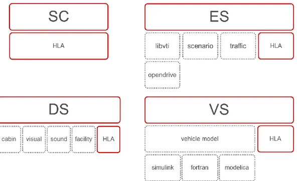
A distributed modular simulation architecture was designed that divides a driving simulator environment into four major entities with well-defined interfaces (Chalmers et al., 2008; Vinter, 2010). These entities are Session Control (SC), Environment Simulator (ES), Driving Simulator (DS) and Vehicle Simulator (VS). DS and VS are as a pair, together called an actor, representing a driver and his/her vehicle. Within the complete simulation environment, it is only allowed to have one SC and one ES but as many actors (DS-VS pairs) as desired. In Figure 1 a schematic view of the distributed architecture is shown with the connections between entities.
Figure 1. Schematic view of the connections between SC, ES, DS, and VS with inter-connections.
From Figure 1 shows that before a simulation can take place, a couple of requirements need to be met: 1. Every entity used within a simulation has to be instantiated and connected.
2. Every entity within the simulation needs to be in ready state. 3. Interfaces between the entities are clearly specified.
In the following, the user needs related to the simulation platform and the four simulation entities are described in detail. The relation to requirements 1 and 2 is explained. Then, considering requirement 3, the inter-connection of the simulation entities and how they interact are explained.
2.1.
User needs
The SimArch final report (Vinter, 2010) identified specific user needs that the SimArch architecture should support. To limit the scope in the work reported here a subset of these user needs was chosen to be focused on, and it was identified that the selected user needs, with their relations to desired
scalability and flexibility of the constructed simulation architecture platform, would still maintain fidelity.
UN1: The system shall support the study of driver behaviour.
UN2: The system shall support prototype testing of models (such as driver models, vehicle dynamics models, traffic models and so on).
UN6: The system shall support both human and simulated drivers.
UN8: The system shall support a programmable vehicle (dynamics) model that is influenced by the traffic environment and the driver.
UN9: The system shall support the assembly of a simulator system with a complexity of choice.
UN10: The system architecture shall be independent of vendor specific hardware and software technologies.
UN12: The system shall support multiple driving simulators to be inter-connected.
UN14: The system shall be able to respond to external stimuli sufficiently fast for a human driver in the loop.
UN16: The system shall not disclose intellectual property.
UN18: The system shall support extraction of variables and parameters from the simulator. The following user needs, that were excluded from the design focus, are not explicitly fulfilled by the resulting design, but may still be fulfilled during a simulation:
UN3: The system shall support prototype testing of software for electronic devices. UN4: The system shall support prototype testing of electronic devices.
UN5: The system shall support the study of traffic flow.
UN7: The system shall support controlled traffic modelled with a complexity of choice. UN11: The system shall support migrating experiments from one simulator to another. UN13: The system shall support V2X communication.
UN15: The system shall support batch execution and evaluation of test scenarios. UN17: The system shall support control of the experiment with event triggered actions. Since UN3, UN4, and UN13 were out of focus, no dedicated entity was included in the design. Thus, there is no support for connecting such devices to the simulation architecture directly and these user needs are not fulfilled by the design. It may still be possible to fulfil these user needs by integrating the software and devices into a specific Vehicle Simulator.
UN5, UN7, and UN17 are dependent on the implementation of the Environment Simulator and the experiment scenario, but are not explicitly included in the design.
UN11 depends on the simulators and technology involved. If custom hardware needs to be installed in the Driving Simulator or Vehicle Simulator, migrating the experiment to another simulator may or may not require a lot of work.
UN15 depends on the implementation of the Session Control application.
2.2.
Session Control
The simulation architecture entity Session Control is responsible for managing the simulation, and is the main point of interaction for the test leader. The SC can be seen as a top-level supervisor that will make sure that every other simulation entity is properly running before and during a simulation but is not affecting the simulation results. Among other functions, it provides the choice of scenario to the test leader as well as the actions of starting and stopping a simulation.
Before starting a simulation, it is the SC’s responsibility to communicate the selected scenario to the other entities. The SC will not create entities upon choosing a specific scenario, but will check that for a certain scenario the required entities exist.
2.2.1. Simulation states
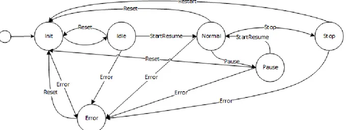
The SC is responsible for making sure that every entity used within the simulation is ready before the simulation starts. To check that a simulation entity is ready a finite state machine has been used for every simulation entity, see Figure 2. Changes between states during normal operation, e.g. going from Normal state to Stop state, are responses to actions made by SC. State changes can also be initiated by the entities themselves. Consider the case where an error occurs and the Error state is set, then SC has to respond to the situation, e.g. resetting every simulation entity.
Figure 2. Finite state machine used in simulation entities.
2.3.
Environment Simulator
The Environment Simulator comprehends the logical description of the simulated environment, including road descriptions, the scenario description, available shapes (e.g. cars, trucks and busses), and traffic control. During the start of a simulation, the test leader (through the SC) chooses one environment together with a scenario. Then ES will keep track of every actor within that environment, and which DS and VS to connect to one actor. The ES uses an OpenDRIVE2 description of the road network, which is an open standard format for describing the logics of a road network (OpenDRIVE®, 2015). The road database to use must be distributed beforehand since in the current implementation it is not the responsibility of ES to distribute it once a scenario has been chosen. Thus, every simulation entity that uses the logical description of the environment needs a copy of the relevant OpenDRIVE file, and the simulation user needs to make sure that versions are synchronized.
ES is responsible for keeping track of every event during the chosen scenario. The scenario, i.e. everything that happens in the course of one simulation run, is executed from the ES. The events are then a specified sequence of actions, and a scenario can consist of one big event or several events. The traffic flow within the environment, and different weather conditions (like snow, fog, rain, wind, and road friction) are examples of environment variables controlled by the ES using actions during an event. Actions can also be used to trigger a certain DS to play sounds to the driver, control secondary tasks, and display text to the driver as well as be responsible for connected physiology equipment that is supposed to be used (such as electroencephalogram (EEG) measurement tools), by sending
2 http://www.opendrive.org/
interactions to a DS. Another option is to control such tools (e.g. EEG measurement tools) directly from a DS.
Since the ES is responsible for all traffic in the simulation, it updates every actor position within the OpenDRIVE world. Thus, each actor reports its velocities to the ES, which then returns an updated position. When a simulation starts, ES provides default road positions for each actor. ES also provides road information, including height, slope, and banking, for each wheel.
2.4.
Driving Simulator
The Driving Simulator represents the driver, either human or modelled. In the former case, the DS includes the physical set-up for the driver. The physical set-up for a human driver may vary but is typically in the range from a desktop simulator using gaming equipment to high-fidelity simulators with a moving base system, several projectors, and an actual car cabin. Thus, DS typically contains visual and audio presentation, a ViP developed software, called VISIR3, is for example used for the visualization of the virtual world in the VTI simulators.
Different physical simulator set-ups also indicate a difference in used hardware platform specifics, e.g. moving base structure, shake table, and buttkickers. The DS may contain specialized hardware for eye movement detection or physiology equipment such as EEG. It could also present different secondary tasks that should be managed by the driver during an experiment, and control cameras for video recording.
During simulation, the DS i.e. the human driver or the driver model, produces driver inputs to the VS such as pedal position, steering wheel angle, selected gear, and position of buttons and switches (e.g. indicators and lights).
2.5.
Vehicle Simulator
The Vehicle Simulator represents the vehicle. This representation is commonly a vehicle model simulating the vehicle systems, but could also be a HiL simulator set-up that uses hardware and models inter-connected in various degrees. An example of such an inter-connected simulation set-up is a complete vehicle’s propulsion system coupled to a vehicle model (see Andersson et al., 2013). The VS includes both physical plant models for the motion of the vehicle, models representing the electrical systems of the vehicle as well as implemented assistance systems, e.g. ABS.
The VS receives driver input from its connected DS as well as a few additional control signals (such as reset) that might be required for motion system safety. If the connection between DS and VS stops, the simulator should stop if it is a moving base simulator. The vehicle also needs to receive road
information such as height, slope and banking, which are provided by the ES.
The VS will send vehicle output signals to ES and DS. Examples of such outputs are velocities, accelerations, engine RPM, and various statuses such as cruise control state.
Whether automatic or manual gearbox is used is decided by the VS, and is not configurable in the scenario or by the DS.
2.6.
Interfaces and communication
To connect the simulation architecture entities, software interfaces have been specified describing how the entities communicate with each other. These connections are shown as blue lines in Figure 1. The specified interfaces are then further divided into two categories: simulation management and runtime. Simulation management specifies signals for handling the simulation, e.g. choosing a scenario and
checking entity states. The runtime signals include signals produced during the simulation execution, e.g. actor positions and velocities. The interfaces specify the messages and data types that may be sent and received by entities in the simulation. With clear interfaces, an implementation of a simulation entity that conforms to the specified interfaces can be seamlessly connected, and it is possible to inter-change different such implementations.
A requirement in this project was to base the specification of interfaces on a standard for distributed simulation. High-Level Architecture (HLA) Evolved, an IEEE standard (Möller et al., 2008) was selected and HLA specific communication methods were used. In HLA, a distributed system is made up of federates in a federation. Thus, within the SimArch architecture, each entity (SC, ES, DS and VS) becomes a federate and together they form a federation. Each federate subscribes and publishes objects and interactions relevant for that specific federate. These features of HLA enable loose
coupling between simulation entities, and makes it possible to use widely different implementations of the entities. Using HLA, federates within a federation can be located anywhere in the world and communicate over Ethernet (including the Internet). In HLA, the communication is managed by the runtime infrastructure (RTI), which provides services to support the federation execution. However, some data exchange requires low latencies, which needs to be taken into consideration when choosing the location of each federate.
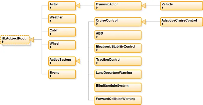
Following the HLA Evolved standard, the communication interfaces are defined in the Federation Object Model (FOM), which is a file on disk with an xml representation, and are often specific for a given federation. As mentioned earlier the SimArch FOM is divided into two categories, one for management of the simulation and one for runtime, here called a management module and a communication module. Each module consists of a specification of objects and interactions that are known within the federation. If an object is not defined in the FOM it will not be possible to communicate information about it. Figure 3 shows the developed communication module with its objects during a simulation, and the management module is shown with its objects in Figure 4. The objects in the management module correspond to federates within the simulation.
Figure 4. Objects used within a federation for management of a simulation.
As seen in Figure 3, the objects used during runtime involve typical objects in the environment, e.g. vehicles and weather. For example, consider an active safety system controlling the steering wheel to avoid an unintended lane departure. In the current implementation, such an object is not present and thus, it is not possible for federates to communicate between each other about such a system. In this case, it would mean that if a VS has such a safety system it cannot tell a connected DS to warn the driver if the system is activated, e.g. consider an Electronic Stability Control (ESC) intervention where the ESC lamp is lit in the driver interface. In this work, it has been prioritized to add common objects so that a typical simulator study could be performed but not so extensively as to cover every simulator study, which is not feasible with the current development and introduction of new systems and signals within vehicles. Instead, it is recognized that the FOM will need to continuously evolve to meet future use cases and requirements.
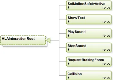
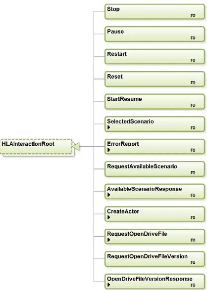
The FOM also defines interactions used within the federation. For the communication module the interactions are shown in Figure 5, and the interactions used by the management module are shown in Figure 6.
Figure 5. Interactions that could be sent within a simulator environment during a simulation.
Each participating entity uses an object defined in the management module to tell others which state it is currently in, see Figure 2 for the finite state machine and Figure 6 for interactions triggering state changes. The SC mostly uses this information, e.g. when all entities have reached the idle state the Start button in the SC user interface will be enabled and the simulation can be started.
It is also possible to add more modules, e.g. facility dependent objects and signals similar to the communication module. For example, there is a separate set of interactions for specific signals used at VTI connected to the control of secondary tasks, e.g. such as the Peripheral Detection Task.
Figure 6. Interactions that could be sent within the federation for controlling the simulation.
In addition to the FOM, there are two other important documents: Conceptual Model (Appendix A) and Federation Agreement (Appendix B).
The conceptual model is “An abstraction of what is intended to be represented within a simulation environment…” and “…describes what the simulation environment will represent, the assumptions limiting those representations, and other capabilities needed to satisfy the user’s requirements…” (IEEE, 2010). The conceptual model for SimArch 2 thus contains for example the definition of an actor, how to handle logging, and the definition of the road network. The complete SimArch 2 conceptual model can be found in Appendix A.
The federation agreement can be seen as a design specification, or contract, for the federation. It provides requirements for inter-operability aspects of any participating federate. The federation agreement spans a wide range of programming and technical issues that must be addressed to successfully design and execute a distributed simulation system, e.g. common coordinate systems, algorithms, etc. For instance, the federation agreement for SimArch 2 specifies used coordinate systems, units for signals such as velocity, and actor reference points which describe how an actor is positioned (e.g. a car at a specific position means that the centre of the front axle of the car is at the specified position). The complete federation agreement can be found in Appendix B.
2.6.1. Runtime phases
When running a simulation, three different global phases are used: pre-runtime, runtime, and post-runtime. Before the pre-runtime phase starts every federate need to connect to the federation. By design federates are not allowed to connect to the federation during a scenario.
During the pre-runtime phase, all federates create local HLA instances, beginning with their own Simulator instance (see objects in Figure 4), i.e. a DS creates its DrivingSimulator instance, followed by federate type specific instances (see objects in Figure 3) before proceeding to the init state. At this point a DS has created its Cabin instance, and VS its Vehicle, Wheel, and if any, ActiveSystem instances. Once in init state, DS, VS, and ES wait for the SelectedScenario interaction from SC. From this point in the pre-runtime, the flow of information is shown in Figure 7.
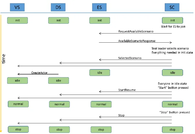
Figure 7. Federation management during pre-runtime and runtime.
As seen in Figure 7, when SC detects an ES, SC sends the RequestAvailableScenario interaction and the ES responds with the AvailableScenarioResponse interaction. All available scenarios are thus sent to the SC application where they are presented to the simulator user. Once a scenario has been chosen by the simulation user, the SelectedScenario interaction is sent, including the name of the scenario, the road database file to use, and which DS and VS federates to connect as actors. Each federate then performs implementation specific initialization, e.g. initializing the cabin and moving base in DS. One important step in the pre-runtime phase is to connect the DS and VS pairs into actors. This connection is initiated by the DS, which uses the information about the selected scenario to send the CreateActor interaction to its VS. The VS responds by setting the MasterDrivingSimulator attribute in its
VehicleSimulator instance. At this point ownership is transferred between DS, VS, and ES for some attributes in the Cabin, Vehicle, and Wheel instances. Once all initialization is done and the federates are ready to begin the simulation, they change to idle state which is notified to the SC. At this point the simulator user can initiate the StartResume interaction from SC to every other federate transitioning to the runtime phase.
During runtime, ES, DS and VS federates exchange simulation data, while the SC has a supervisor role indicating the state of the federates to the test leader. At the end of the scenario, SC sends the Stop interaction to transition to the post-runtime phase.
In post-runtime, federates save simulation data and perform implementation specific clean-up, e.g. parking a simulator using a moving base system. Federates transition back to the pre-runtime phase when the Restart interaction is received from SC, activated by the test leader. Local HLA instances are not deleted until Restart is received.
If any federate reports an error it is up to the test leader to take action. No automatic error recovery is currently performed.
2.6.2. HLA workflow and tools
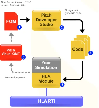
As mentioned earlier, the HLA Evolved standard defines a set of documents and files that needs to be created. These files grow in numbers and size for every signal and object within the federation, and the files are hard to maintain manually. Thus, existing tools provided by Pitch Technologies4 were used to generate these files. In order to create the FOM the Pitch Visual OMT tool was used. The FOM is represented as an XML description containing all objects and signals within a federation. Pitch Developer Studio was used to generate the HLA layer that provides an interface to the federation. The workflow can be seen in Figure 8.
Figure 8. Pitch Visual OMT and Pitch Developer Studio workflow.
The FOM created in Pitch Visual OMT is loaded into Pitch Developer Studio. In Pitch Developer Studio, the user may choose all the objects and signals that the federate is going to use during the simulation. Pitch Developer Studio will then generate the header files and libraries that are to be linked from the federate application. The generated code follows the HLA standard and is compliant
with any certified RTI. Each federate application will only use the parts of the FOM that are relevant to it. This means that only a subset of the FOM is applied during code generation.
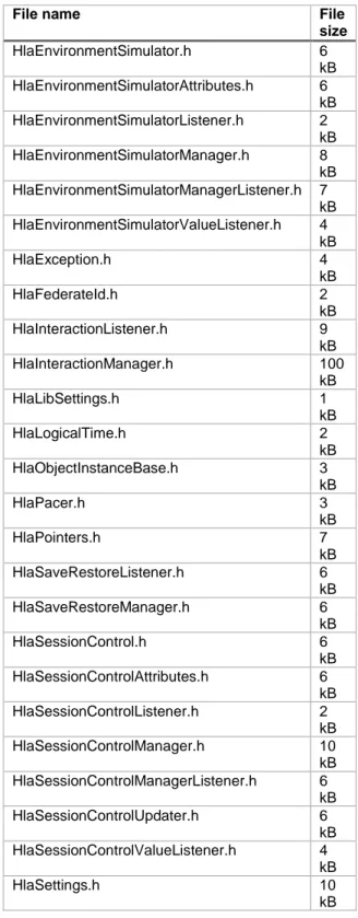
For an example of generated files see Table 1 where a subset, created by the Pitch Developer Studio tool, is shown. Here it can be seen that objects such as the Environment Simulator are declared in a header file. Each object has functions for managing them, working with attributes, and listening for changes to them.
Table 1. A view of some of the generated files used by Session Control. File name File
size HlaEnvironmentSimulator.h 6 kB HlaEnvironmentSimulatorAttributes.h 6 kB HlaEnvironmentSimulatorListener.h 2 kB HlaEnvironmentSimulatorManager.h 8 kB HlaEnvironmentSimulatorManagerListener.h 7 kB HlaEnvironmentSimulatorValueListener.h 4 kB HlaException.h 4 kB HlaFederateId.h 2 kB HlaInteractionListener.h 9 kB HlaInteractionManager.h 100 kB HlaLibSettings.h 1 kB HlaLogicalTime.h 2 kB HlaObjectInstanceBase.h 3 kB HlaPacer.h 3 kB HlaPointers.h 7 kB HlaSaveRestoreListener.h 6 kB HlaSaveRestoreManager.h 6 kB HlaSessionControl.h 6 kB HlaSessionControlAttributes.h 6 kB HlaSessionControlListener.h 2 kB HlaSessionControlManager.h 10 kB HlaSessionControlManagerListener.h 6 kB HlaSessionControlUpdater.h 6 kB HlaSessionControlValueListener.h 4 kB HlaSettings.h 10 kB
These generated files give access to the RTI used and thus no low-level programming with the RTI is needed. The generated code is compiled into a library file and then used together with the header files when developing the federates. For an example of how generated and used C++ code looks like see Figure 9.
Figure 9. Example code from vehicleupdatelistener.cpp used in Session Control.
The generated C++ code is integrated into the existing code base. For an overall layout sketch of how code used at VTI has been modified see Figure 10. Here it can be observed that every entity has an HLA component, which consists of generated files increasing the code base for each entity. It can also be seen that SC only contains an HLA layer. The reason for this is that classes for handling a
distributed simulation were not part of the code base at VTI earlier, but have been developed in the course of the SimArch 2 project.
Figure 10. Modifications (shown in red) done to CORE at VTI to adapt to the SimArch architecture. Classes pictured under entities are examples of existing classes but is not a complete list.
During the project the workflow described above was iterated several times. The FOM would be updated with new attributes, generated files would be regenerated and then integrated into the simulators. This made it easy to extend the functionality of the HLA layer.
Another important tool is the Pitch Booster, which was used to connect different Local Area
Networks. The Local Area Networks could be two networks at the same location (where one network is a restricted security network and the other network would allow internet access) or two
geographically separated networks such as VTI’s and VCC’s locations in Gothenburg. Pitch Booster creates something similar to a Virtual Private Network, but for simulation traffic. One Pitch Booster needs to be installed in each network that should be connected and then dedicated connections are made between the Pitch Boosters. The firewalls at each network only have to be configured to allow network traffic to and from the booster. When running simulators over the booster network the use of the booster is transparent for the user which simplifies running distributed simulations.
3.
Hardware platforms
To evaluate the distributed simulation architecture platform different simulators were used, both individually and in different combinations. Included simulators were: VTI’s high-fidelity moving base driving simulators Sim II, Sim III and Sim IV, VTI’s small moving base driving simulator SimFoerst, and a HiL simulator at VCC. SimFoerst, Sim II, and Sim III are located in Linköping while Sim IV and the HiL simulator at VCC are located in Gothenburg. These simulators are further described below.
Simple desktop simulators have been used as well, consisting of normal consumer computers with a connected gaming steering wheel and pedals.
3.1.
VTI driving simulators
VTI has four moving base simulators that have been used in the SimArch 2 work. These simulators5 are Sim II, Sim III, Sim IV, and SimFoerst.
SimFoerst is a 2DOF moving base simulator. It has three screens presenting the front view to the driver, and also rear view mirrors. Sound is presented to the driver using a 5.1 speaker system. In this set-up, the SimFoerst simulator was used without motion and is thus here considered a fixed-base simulator.
Sim II is a high-fidelity driving simulator with a Scania truck cabin. The moving base consists of an outer motion with a linear movement and cylinders for tilting and rolling the whole platform. The cabin is mounted on a vibration table used for producing high frequency road irregularities (Bolling et al., 2011). The front view is presented on a curved screen by six HD projector images blended together to create a single view, providing 105º horizontal field of view. LCD displays are used as rear view mirrors. Sound is presented to the driver through cabin speakers together with additional speakers to create surround sound.
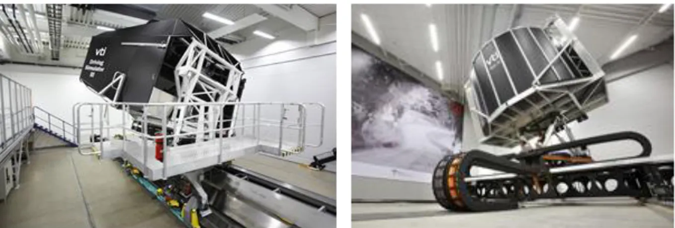
Sim III (left picture in Figure 11) is a passenger car driving simulator (Nordmark et al., 2004) with a SAAB 9-3 cabin. The motion system as well as the visual and sound presentation, similar to Sim II, with a 120º field of view in Sim III.
Figure 11. Moving base simulator Sim III at VTI in Linköping to the left and the moving base simulator Sim IV at VTI in Gothenburg to the right. (Photo: Hejdlösa Bilder).
Sim IV (Jansson et al., 2014) is used for both truck and passenger car driving using Volvo cabins. As can be seen in the right picture in Figure 11, a moving base table provides linear motion in both longitudinal and lateral direction. A hexapod is used for tilt, roll, pitch and smaller movements. The
front view is presented on a curved screen by nine projectors and the simulator has about 180º horizontal field of view, depending on which cabin is used.
Common for the simulators Sim II, Sim III and Sim IV is the security system that shuts down the network connection to the outside during operation and only runs a local network. This is to protect an ongoing simulation from external network disturbances. When running a distributed simulation, this security feature has been modified by allowing one connection to the simulator network by using Pitch Boosters as described in section 2.6.2.
3.2.
VCC HiL simulator
The VCC HiL simulator represents a car that is composed of Volvo’s newest platform, known as the Scalable Product Architecture (SPA). The HiL simulator is a virtual vehicle containing, more or less, all physical Electronic Control Units (ECUs) for the complete electrical system of a car. These ECUs are connected to the HiL simulator, together with a number of plant models and a vehicle dynamics model. Everything runs under real-time conditions and the ECUs are stimulated so that the HiL environment is indistinguishable from a real vehicle to the ECUs. This enables for example
verification of functions that require dynamical conditions, such as Active Safety functions (e.g. auto brake), Adaptive Cruise Control (ACC), and plenty of other functionalities.
The VCC HiL simulator, shown in Figure 12, consists of three separate units for HiL simulation, all connected to each other. Together they represent a simulation environment of a complete vehicle. The middle part of Figure 12 shows the driver cockpit, including an infotainment system and a 3D
rendering computer for visualization. Various car parts with their respective ECUs are connected to the HiL simulator, mainly visible on the table to the left in Figure 12.
Figure 12. The VCC HiL-simulator including the three separate units for HiL-simulation and driver interface (Photo: VCC).
The HiL simulator executes on a third party real-time processor which is not directly HLA compatible. Therefore, it must be connected to a separate PC application in order to interface properly with the distributed simulation. In this way, the application works as a kind of gateway that enables the HiL simulator to become a VS federate, connected to a local desktop DS, and execute within the distributed simulation architecture.
4.
Results
The evaluation of the platform focused on two aspects. The first aspect is timing performance and the second aspect is the flexibility and scalability of the simulator platform. These aspects are further presented in chapters 4.1 and 4.2 below.
Another important result of the SimArch 2 project, presented in chapter 4.3 below, was two
successfully performed demonstrations, where interested parties were invited to see and experience the distributed simulation architecture in operation.
4.1.
Time measures
Two approaches have been used to evaluate the timing performance, which are
1. to send dummy packages that resemble a distributed simulation as much as possible, and 2. to use the software utility Ping.
In the first approach, packages using the actual package structures that would be sent during a simulation with static dummy data were used. Thus, values for vehicle velocities and accelerations were sent although the actual sent velocity and acceleration were static values. When the package was received at the remote destination it was immediately sent back. When the package was received back, the round-trip time (RTT) was logged. This RTT measurement was also done using the HLA layer. In Figure 13 parts of one RTT measurement, using the HLA layer between a server at VTI in Linköping and Sim II and Sim IV, is shown. Packages were sent at the same frequency as used during a typical simulation, which was set to 200 Hz.
Figure 13. RTT measure within local network from server at VTI in Linköping at different simulators.
For evaluation, three different RTT tests were performed for each simulator during the night when it was expected to have a low utilization of the network. Using Sim II resulted in a median RTT value ranging from 1.06 ms to 1.14 ms, and when connecting to Sim IV in the same manner the median RTT range was 12.56 ms to 12.67 ms. The difference in measured RTT is mainly due to the difference in physical distance between the measurement computer and the respective simulator. Sim II is located in close vicinity, while for Sim IV the distance in-between is approximately 280 km. If instead using Ping to estimate the connection latency to Sim II it was approximately 0.25 ms, and in Sim IV the
latency was approximately 11.5 ms. An explanation of the higher latency using an RTT measure instead of a Ping is that the implementation of HLA includes decoding and encoding of the transmitted data as well as calling the listeners in the HLA layer. From these time measurements, the added communication overhead when using HLA in this implementation is estimated to be approximately one millisecond.
As mentioned in section 2.6.2, Pitch Developer Studio was used to generate the HLA layer. It would be possible to write the code by hand instead in order to tailor it for each federate. This could reduce the measured latency, but would add complexity and increase the cost to maintain the code.
4.2.
Platform flexibility and scalability
Interfaces between simulation architecture entities have been implemented and a federation with federates of SC, ES and actors have been executed. No issues were found when running a simulation using a desktop configuration. Running the federation with the simulators SimFoerst, Sim II, Sim III, Sim IV, and the VCC HiL simulator, the federation execution worked properly when running the federation internally at the simulators. Connecting simulators have also worked fine, and tests running simulators together in the same federation with the moving base systems active and moving also worked properly. Thus, issues with the moving base simulators’ safety system shutting down the network connection were solved with the Pitch Boosters.
Distributed cases that were tested are: 1. In Linköping only.
2. Distributed between Gothenburg and Linköping.
3. Distributed between Paris and Linköping with the SC located in Paris.
The major configurations of distributed simulations that were tested are shown in Table 2 (the demonstration configurations are not part of these test runs).
Table 2. The major distributed configurations tested during evaluation of the platform.
SC ES DS+VS
Server in Linköping Linköping Sim II and Sim III without motion Laptop in Paris Server in Linköping Sim III without motion
Server in Linköping Server in Linköping VCC HiL simulator Server in
Gothenburg
Server in Gothenburg
VCC HiL simulator
For the integration of HLA into existing code repositories, a tool was used to generate code as described in section 2.6.2. The code generation included functionality to connect to a federation and manage federation objects, attributes and interactions defined in the FOM. Using this layer, adapting VTI’s existing simulator software to use HLA was at VTI perceived as quite straightforward, by adding a communication layer to each simulator entity that sends/receives data on HLA and converts data between HLA and internal data types. Simulator specific code (e.g. cabin and moving base) has been encapsulated inside the DS application, completely detaching it from the vehicle model, thus increasing the flexibility.
The scalability, which was defined as how easy it is to add more actors to the simulation environment, was evaluated by connecting several actors to the environment. No problems were encountered adding actors to the federation, and as can be seen in Table 3 additional actors add linearly to the total number of callbacks. Thus, it is possible to give a rough estimate of how many actors that can be added during a simulation depending on the network bandwidth.
A HLA functionality that was not used during the SimArch 2 project is DDM (Data Distribution Management). This functionality was not implemented in Pitch Developer Studio at the time of the project but has since then been implemented. A first layer of filtering or data distribution management in HLA applied in this project was to specify the data that a federate shall receive on a class level. For example, a DS would specify that it wants updates for the TractionControl object class and would then receive updates for all traction control objects. However, if a specific DS is only interested in the updates of the traction control instance which is attached to the specific VS that the DS is paired with as an actor, then a second layer of filtering is needed. When using DDM the DS can add this second layer of filtering specifying the instances of an object class from which it wants updates. This would reduce the incoming updates for the DS and further reduce the load on the network, thus increasing the scalability of the simulation architecture.
Table 3. Call rate and callback rate per federate during simulation.
Federate Call rate Callback rate
1 actor ES 200 1000 DS 1000 600 VS 400 1200 2 actors ES 400 2000 DS 1000 2200 VS 400 2800 3 actors ES 600 3000 DS 1000 3800 VS 400 4400 4 actors ES 800 4000 DS 1000 5400 VS 400 6000
4.2.1. Connecting the VCC HiL simulator and HLA
A few considerations were needed when connecting the VCC HiL simulator to a HLA federation. As was briefly mentioned in section 3.2, the HiL simulator should interface with the HLA federation via a regular Windows PC. This PC runs the VCC VS federate code and must receive relevant data, such as vehicle speed, updated from the HiL simulator. The HiL simulator needs to communicate with the HLA federation under real-time circumstances (both reading and writing data). Therefore, filters were used to approximate and predict certain real-time demanding data, such as radar object data from ES and vehicle speed data sent from the HiL simulator to the federation.
Another problem was the communication protocol used to interface with the HiL simulator. The protocol only allowed to read or write one variable at the time, and each such operation would take around 1.5 ms. Thus, even a moderate number of variables introduce problematic delays. To solve this, a prioritization algorithm was introduced and incorporated with the filters mentioned above, estimating the difference between the HiL’s predictions and the incoming data. The data for a given signal is then forwarded only if the difference would otherwise exceed that signal’s tolerance. Data from the HiL can be accessed according to each signal’s assigned priority, where e.g. vehicle speed could be more prioritized than exterior lights.
Furthermore, an interesting set-up is the combination of VCC’s HiL simulator as a VS with a DS at another location (e.g. Sim IV at VTI). The goal is to keep the HiL simulator as complete as possible hardware-wise. This is a challenge, because not all the physical hardware can easily be stimulated electronically, such as mechanical buttons. For example, in the demonstrated system the HiL’s ECU containing the ACC manoeuvring buttons had to be removed and replaced by a simplified model. The reason was, apart from having some sort of robot arm to push the physical buttons, that there was no
way for the DS to activate the ACC function via the HLA federation. However, with the simplified model, the DS can interact with the virtual buttons instead. Hence, the more driver interface related functionality is handled by the DS, the less physical hardware can be incorporated in the HiL simulator.
4.3.
Demonstrations
Two demonstrations of the distributed simulation architecture with active moving base simulators were performed, one in Gothenburg on November 12th 2015 and one in Linköping on December 9th 2015. These demonstrations were open for anyone with an interest in the distributed simulation architecture, and an invitation was sent to ViP partners with a suggestion to forward it to interested parties. Both demonstrations performed shared the layout with an introductory presentation of about 20-30 min and then about an hour of driving in the respective simulators.
4.3.1. Demonstration in Gothenburg
The distributed simulation architecture configuration used during the demonstration in Gothenburg is shown in Figure 14. To give participants at Sim IV a notion of the state of the VCC HiL simulator and vice versa a video conference system was used showing the connected simulators.
Figure 14. Simulator configuration (demonstration set-up) used in Gothenburg 12 November 2015.
The goal of the Gothenburg demonstration was to show that the VCC HiL simulator, Sim IV and a simple desktop simulator actor could execute together in a common environment and also dynamically interact with each other. To show that an advanced vehicle function requiring real time timing
conditions could be executed, VCC’s ACC function was chosen as a demonstration example. The demonstration was done by letting the VCC HiL simulator actor, controlled by a human driver, drive behind the other actors. The ACC function was activated and the VCC HiL simulator was then allowed to adapt to whatever speed the vehicle in front was keeping. This included accelerations and braking manoeuvres, all the way down to stand-still. After the ACC function was demonstrated successfully, participants were invited to test the configuration during free driving.
From the demonstration in Gothenburg it could be concluded that connecting the simulators is
possible. However, it also showed that having several complex simulators connected together requires the respective systems to be stable and redundant. Otherwise there will be a lot of time wasted in order to make everything reach a ready-state to start. Since the simulator set-ups were not very robust, a lot of communication between the operators at VTI and VCC was required.
It is also worth mentioning that the VCC HiL simulator is protected by firewalls and a temporary solution using a cell phone had to be used. This increased the latency between the actors, but apart from that the connection set-up worked out well and no disconnections from the federation could be observed. The increased delays were mostly noticed in VISIR’s graphical presentation at VCC, due to low update frequency.
4.3.2. Demonstration in Linköping
With several project partners at different locations in Sweden not everyone could participate during the demonstration in Gothenburg. Giving a second chance to these partners, a second demonstration was performed in Linköping. The configuration used in Linköping, shown in Figure 15, included both the simulators Sim II and Sim III.
Figure 15. Simulator configuration (demonstration set-up) used in Linköping 9 December 2015.
Using the simulators Sim II and Sim III was beneficial from a couple of aspects. First, since the simulators are located in close vicinity it was easy to physically connect the simulator networks. The demonstrated configuration used two internal networks since the simulators used their own networks closed-off during simulation. This resulted in high network performance. Another benefit of the close vicinity was that the simulator operators could visually see each other checking the progress of the initialization, see left part of Figure 16 (a foldable wall was raised to have a direct line of sight between the two simulators). This reduced the communication effort, although some communication was still necessary. The benefit of seeing each other also applies to the participants as it was easy to follow the start-up procedure of each simulator since both were visible. A third benefit was that the connected simulators have been operational for a long time and operation procedures are well established and robust.
Figure 16. Pictures taken during the demonstration in Linköping showing the simulators Sim II and Sim III and a desktop simulator running in the same simulation environment (Photo: VTI).
Many of the mentioned benefits during the Linköping demonstration are results of the configuration being at one site in a low latency set-up. In a situation where simulator hardware typically cannot be moved, this configuration is very rare, consider e.g. how many facilities there are worldwide that facilitates two moving base simulators in the same room. Thus, the configuration used in Gothenburg might be more common, but from a demonstration perspective the Linköping configuration proved to work very well.
5.
Conclusions
Results produced so far look promising and the possibility to run a federation with several actors, with and without moving base systems, within a local Ethernet network has been shown to work properly. Thus, the new driving simulator platform is an extension as it maintains the original functionality while adding new functionality. Among the new functionalities is the additionally obtained flexibility and scalability.
An important aspect is the clear definition of interfaces which can be used as a specification. Thus, it is possible to give the interface specification to another partner and if the partner properly complies with the necessary signals, the simulation will be carried out without problems.
Measurements of communication time lead to the conclusion that the explained implementation has a time overhead latency of approximately one millisecond. This could be a problem in simulator
experiments where strict timing and short time delays are required. The communication time probably needs a more detailed investigation when there is communication between physically separated VS and DS. For the communication with other entities within the federation, the extra overhead latency is considered negligible. For example, this overhead latency is negligible for the visualization since the time between updates of the visual scene using a 60 Hz screen is 16.67 ms. Thus, for many simulator experiments where the VS and DS are located at the same location, the ES and SC can be distributed to achieve flexibility, while maintaining simulator fidelity.
Compared to the previous simulation architecture a similar set-up is kept, but parts of the simulation can be executed at variable locations. Hence, the new platform is considered more flexible, and definitely more scalable. The obtained flexibility was shown with respect to connecting HiL
equipment and was demonstrated during two final demonstrations. The user friendliness can be a little more cumbersome since a developer gets more interface code to maintain, but on the other hand the major part of the code base can be treated as a black box. Using distributed simulation also puts more effort on the SC implementation, so that errors are easy to understand when a simulation does not start or is not working as intended. These issues need to be evaluated against the effects of increased scalability and flexibility. For the current implementation, it has been estimated that the added value of flexibility and scalability is more important than the added complexity. The importance of added flexibility is more clear for cases in which simulation set-ups should be transferred from simpler to more advanced simulators.
The developed software is available within ViP where it can be tested as shown during the demonstrations. If a new federate is to be interfaced extra work is needed e.g. for another HiL simulator. Use of development tools is recommended. The current software builds a good foundation for future extensions.
5.1.
Future Work
Future investigation of this distributed simulation architecture will consider timing issues when running a federation between driving simulators and vehicle simulators. There is a lot of information sent that is only necessary for the respective DS-VS pair, but currently the information is sent to all simulators (as can be seen in the callback rate column in Table 3). A first approach would be to use DDM as a technique to reduce the number of callbacks and therefore to increase the performance. Another possible performance enhancement could be to introduce prediction of simulation states since accurate prediction reduces the communication rate.
In addition, for some simulated models the actor information needs to be updated at 1000 Hz. Here a further investigation of the coupling between the DS and the VS is needed to see if this requirement can be fulfilled to maintain simulator fidelity during a distributed simulation. If the frequency requirement needs to be reduced, driver behaviour and driver-to-vehicle interaction should be further
validated to ensure that results similar to real world driving are achieved. For parts that need an update rate of 1000 Hz an evaluation of the possibility to adjust the HLA layer to be more effective is
References
Allen, R. W., and DiMarco, R. J. (1984). Effects of transport delays of manual control system performance. In Proceedings of the 20th annual conference on manual control, pp. 185-201, Moffet Field, CA, US: NASA.
Andersson, A., Nyberg, P., Sehammar, H., and Öberg, P. (2013). Vehicle Powertrain Test Bench Co-Simulation with a Moving Base Simulator Using a Pedal Robot”. SAE International Journal of
Passenger Cars - Electronic and Electrical Systems, 6(1), pp. 169-179.
Anderson, A., Andersson Hultgren, J., Leandertz, R, Johansson, M., Eriksson, S., and Jakobson, O. (2015). A Driving Simulation Platform using Distributed Vehicle Simulators and HLA. In
Proceedings of Driving Simulation Conference & Exhibition (DSC 2015 Europe), Germany,
Tübingen, 16-18 September, 2015, pp. 123-130.
Bolling, A., Jansson, J., Hjort, M., Lidström, M., Nordmark, S., Sehammar, H., and Sjögren L. (2011). An Approach for Realistic Simulation of Real Road Condition in a Moving Base Driving
Simulator. J. Comput. Inf. Sci. Eng, 11(4), pp. 041009:1 – 041009:7, doi:10.1115/1.4005450. Chalmers, S., Nilsson, J., Edler, H., and Kemp, G. J. (2008). An Ontology-Based Approach to Car
Simulation and Design. In Proceedings of Third Asian Semantic Web Conference, pp. 270-275, Bangkok, Thailand.
IEEE (2010). IEEE Recommended Practice for Distributed Simulation Engineering and Execution Process (DSEEP), Standard 1730-2010, IEEE.
Jansson, J., Sandin, J., Augusto, B., Fischer, M., Blissing, B., and Källgren, L. (2014). Design and performance of the VTI Sim IV. In Proceedings of Driving Simulation Conference (DSC Europe
2014), Paris, France, 4-5 September, 2014, pp. 04.1-04.7.
Möller, B., Morse, K. L., Lightner, M., Little, R., and Lutz R. (2008). HLA Evolved – A Summary of Major Technical Improvements. In Proceedings of the Fall 2008 Simulation Interoperability
Workshop, Orlando FL, pp. 15-19.
Nordmark, S., Jansson, H., Palmkvist, G., and Sehammar, H. (2004). The new VTI Driving Simulator - Multi Purpose Moving Base with High Performance Linear Motion. In Proceedings of Driving
Simulation Conference (DSC 2004), Paris, France, 8-10 September 2004, pp. 45-55.
OpenDRIVE® (2015). Format Specification, Revision D. OpenDRIVE® V 1.3. Retrieved from http://www.opendrive.org/download.html April.
SimArch 2 – Conceptual Model June 26, 2013
Page 2
Introduction
This document describes the conceptual model of the SimArch 2 system. The definition and use of the conceptual model within SimArch 2 project will follow the DSEEP standard (Distributed Simulation Engineering and Execution Process) as published by IEEE [1]. The definition of a conceptual model as defined in the DSEEP:
“conceptual model: An abstraction of what is intended to be represented within a simulation environment, which serves as a frame of reference for communicating simulation-neutral views of important entities and their key actions and interactions. The conceptual model describes what the simulation environment will represent, the assumptions limiting those representations, and other capabilities needed to satisfy the user’s requirements. Conceptual models are bridges between the real world, requirements, and design.”
As a trivial example; if one of the objectives of the simulated environment is to simulate cars, the conceptual model will contain a concept called “car” and a description of what a “car” is.
One of the major benefits of having a conceptual model is that it will help make sure that the simulators (reused or newly developed) will be able to simulate all different parts of the desired simulated environment. In the example above we have to have an application that has the capability to simulate cars. By mapping everything in the conceptual model to an application we can make sure that the resulting simulated environment will be able to fulfill all objectives.
One important aspect of the conceptual model is that it should be simulation-neutral. This means that when creating the conceptual model there should be no assumptions of what kind of
interoperability standard (for example HLA or DIS) will be used to exchange information between simulators.
Limitations
When creating a simulated environment there will always be a set of objectives that it should fulfill. A conceptual model can only be determined to cover a certain set of objectives. It is not feasible to create a conceptual model that covers all concepts that can be present in a SimArch 2 simulation. The limitations of the model, together with motivations, can be found in the Federation Agreement.
Revision history
Version Date Author(s) Description
0.1 2013-04-26 Jonas Andersson Hultgren (VTI) First draft (WP1) 0.2 2013-05-14 Jonas Andersson Hultgren (VTI) Second draft (WP1) 0.3 2013-06-26 Jonas Andersson Hultgren (VTI) Third draft (WP1) 1.0 2014-03-03 Martin Johansson (Pitch) Tagged as v1.0
References
[1] 1730-2010 - IEEE Recommended Practice for Distributed Simulation Engineering and Execution Process (DSEEP)
SimArch 2 – Conceptual Model June 26, 2013
Page 3
Related documents
SimArch 2 – Federation Agreement
Top level concepts
The following concepts have been identified as needed to be able to describe the desired simulated environment:
Name Short description
Simulation state Describes which state the simulation is in Session control Supervising and managing the simulation
Actors Objects in the simulated world
Vehicle A type of dynamic actor
Traffic Traffic used to create a realistic environment Weather Weather effects that may affect the simulation
Friction Road surface friction
Cabin The physical controls a driver uses
Driver The driver of a vehicle
Road network Logical description of road network
Analysis data Data not used in the simulation but will be logged
Event A situation within a scenario
Scenario Overall experiment description. Set of actions and triggering conditions
Logging Recording data for later use Secondary task Used to distract the driver
Each concept is described in detail below.
Simulation state
The applications of the simulation will be governed by a state machine. All state machines will have the same set of states, but the conditions for transitioning between each state will differ between applications. See the table below for the list of possible states (see section 3.1.1 “Entity control” in the SimArch Final Report [2] for more information).
Super state State
Pre-runtime Startup Init Idle Runtime Normal Test Pause
Post runtime Error