Extended Product Models
Supporting Multidisciplinary
Design Automation
Doctoral Thesis Tim Heikkinen Jönköping University School of EngineeringExtended Product Models
Supporting Multidisciplinary
Design Automation
Doctoral Thesis Tim Heikkinen Jönköping University School of EngineeringDoctoral Thesis in Machine Design
Extended Product Models Supporting Multidisciplinary Design Automation
Dissertation Series No. 060 © 2021 Tim Heikkinen Published by
School of Engineering, Jönköping University P.O. Box 1026
SE-551 11 Jönköping Tel. +46 36 10 10 00 www.ju.se
Printed by STEMA AB, year 2021 ISBN 978-91-87289-64-4
Trycksak 3041 0234
Acknowledgements
This work was carried out at Sweden’s Jönköping University in the Department of Industrial Product Development, Production and Design and the research group Product Design and Development.
I am very grateful to Sweden’s innovation agency (Vinnova), the Knowledge Foundation (KK-stiftelsen), Region Jönköping County, and Jönköping University for funding my research projects. Special thanks must be extended to the wonderful employees of the industrial partners within these projects who have given me invaluable feedback and access to real-world contexts.
I would also like to express my utmost appreciation for Fredrik Elgh and Joel Johansson, who initially introduced me to the wonderful world of design automation and have given me the opportunity and patiently guided me through this research process within it. I also thank Roland Stolt, who came in late to this journey but managed to catch up and support it anyway.
I offer my special thanks to Samuel André, Djordje Popovic, Karl-Johan Jonsson, and Mohammad Rad for many hours of fruitful discussion. Thank you as well to all my colleagues at the Department of Industrial Product Development, Production and Design for contributing to a pleasant work environment.
Finally, thank you to my family and friends for your continuous encouragement and support.
Abstract
Manufacturing organizations often pursue the ability to efficiently and effectively provide custom products for its competitive advantage. Research has shown product configuration to be an effective way of achieving this goal through a modularization, product platform, and product family development approach. A core assumption behind this approach is that the module variants and their constraints are explicitly pre-defined as product knowledge. This is not always the case, however. Many companies require extensive engineering to develop each module variant but cannot afford to do so proactively to meet potential customer requirements within a predictable future. Instead, they attempt to implicitly define the module variants in terms of the process in which they can be realized. In this way, manufacturing companies develop module variants on demand efficiently and effectively when customer requirements are better defined, as justified by the increased probability of profiting from the outcome.
Design automation (DA), in its broadest definition, refers to computerized engineering support that efficiently and effectively utilizes pre-planned reusable assets to progress a design process. The literature has reported several successful implementations of DA, but especially widespread higher levels of automation are yet to be seen. One DA approach involves the explicit representation of engineering process and product knowledge in the engineers preferred formats, such as computer scripts, parametric geometry models, and template spreadsheets. These design assets are developed using various computer tools, maintained within the different disciplines involved, such as design, simulation, or manufacturing, and are dependent on each other through the product model. To implement, utilize, and manage DA systems in or across multiple disciplines, it is important to understand how the disciplinary design assets depend on each other throughout the product model and how these relations should be constructed to support users without negatively affecting other aspects, such as modeling flexibility, system transparency, and software tool independence.
To support the successful implementation and management of DA systems, this work focuses on understanding how digital product model constituents are, can, and, to some extent, should be extended to concretize relations toward and between design assets from different tools and disciplines. This research consists of interviews with Swedish industrial companies, technical reviews, literature reviews, and prototype developments, resulting in an increased understanding and the consequent development of a framework that highlights aspects regarding the choice and development of extension techniques.
Appended papers
Paper I
Tim Heikkinen, Joel Johansson, and Fredrik Elgh, “Extended CAD-Models – State of Practice within Three Companies”, International Conference on Industrial Engineering and Engineering Management, Singapore, 2017.
Work distribution: Tim Heikkinen planned and executed the interview study and wrote the paper. Joel Johansson and Fredrik Elgh helped choose case companies and provided contact information, in addition to structuring and proofreading the paper. Paper II
Tim Heikkinen, Joel Johansson, and Fredrik Elgh, “Review of CAD-Model Capabilities and Restrictions for Multidisciplinary Use”, Computer-Aided Design and Applications, 2018.
Work distribution: Tim Heikkinen performed the technical review, developed the prototype system, and wrote the paper. Joel Johansson provided access to an implementation of the reviewed automation method, described how it worked, contributed to the technical review through discussions, and helped structure and proofread the paper. Fredrik Elgh helped structure and proofread the paper.
Paper III
Tim Heikkinen, Joel Johansson, and Fredrik Elgh, “Extended Design Assets Enabling Automated Tool Development as a Part of a Product Platform Approach”, International Design Conference, Croatia, 2018.
Work distribution: Tim Heikkinen developed the prototype system and wrote the paper. Joel Johansson supported the author by contacting the case company, choosing the production preparation focus, and structuring and proofreading the paper. Fredrik Elgh lent support with the paper structuring and proofreading.
Paper IV
Tim Heikkinen, Joel Johansson, and Fredrik Elgh, “Multidisciplinary Design Automation – A Conceptual Framework for Working with Product Model Extensions”, International Journal of Agile Systems and Management, 2020.
Work distribution: Tim Heikkinen developed the conceptual framework and wrote the paper. Joel Johansson and Fredrik Elgh helped structure and proofread the paper. Paper V
Tim Heikkinen, Roland Stolt, and Fredrik Elgh, “Incorporating Design for Additive Manufacturing in Multidisciplinary Design Automation – Challenges Identified”, Computer-Aided Design and Applications, 2020.
Work distribution: Tim Heikkinen developed the integration approach and system prototype, as well as wrote the paper. Roland Stolt and Fredrik Elgh supported the paper through discussions, as well as structured and proofread it.
Paper VI
Tim Heikkinen, “Transparency of Design Automation Systems Using Visual Programming – Within the Mechanical Manufacturing Industry”, submitted to International Conference on Engineering Design, 2021.
Paper VII
Tim Heikkinen, Roland Stolt, and Fredrik Elgh, “Extended Product Models – Dealing with Topological Changes and System Transparency”, submitted to International Conference on Engineering Design, 2021.
Work distribution: Tim Heikkinen further developed the conceptual framework initially presented in Paper IV and wrote the paper. Roland Stolt and Fredrik Elgh supported the paper through discussions, as well as structured and proofread it.
Additional papers
• Tim Heikkinen, Joel Johansson, and Fredrik Elgh, “Assessment of Simulation Ready CAD Models in a Set-Based Concurrent Engineering Context”, International Design Conference, Croatia, 2016.
• Tim Heikkinen, Roland Stolt, Fredrik Elgh, and Petter Andersson, “Automated Producibility Assessment Enabling Set-Based Concurrent Engineering”, Transdisciplinary Engineering, Brazil, 2016.
• Roland Stolt, Joel Johansson, Samuel André, Tim Heikkinen, and Fredrik Elgh, “How to Challenge Fluctuating Requirements: Results from Three Companies”, Transdisciplinary Engineering, 2016.
• Fredrik Elgh, Joel Johansson, Roland Stolt, Martin Lennartsson, Tim Heikkinen, and Dag Raudberget, “Platform Models for Agile Customization – What’s Beyond Modularization?”, Transdisciplinary Engineering, 2018.
• Roland Stolt, Tim Heikkinen, and Fredrik Elgh, “Integrating Additive Manufacturing in the Design of Aerospace Components”, Transdisciplinary Engineering, 2018.
• Roland Stolt, Fredrik Elgh, and Tim Heikkinen, “Design and Evaluation of Aerospace Components for SLM”, Transdisciplinary Engineering, 2019.
Abbreviations
API – Application programming interface CAD – Computer-aided design
CAx – Computer-aided technologies CSP – Constraint satisfaction problem DA – Design automation
DRM – Design research methodology EPM – Extended product model ETO – Engineer-to-order FE – Finite element
KBE – Knowledge-based engineering LoA – Level of automation
LSTO – Lattice-based structural topology optimization
MOKA - Methodology and software tools oriented to knowledge-based engineering applications
Contents
1 Introduction ... 1
1.1 Motivation for research ... 3
1.2 Aim and goal ... 3
1.3 Research questions ... 3
1.4 Scope and delimitations ... 4
1.5 Research projects ... 4
1.6 Thesis outline... 5
2 Research Approach ... 7
2.1 Design research methodology... 7
2.2 Action research ... 9
2.3 Empirical data collection ... 10
2.4 Evaluation ... 10
2.4.1 Validation square ... 11
2.5 Applying the research approach ... 12
3 Frame of Reference ... 15
3.1 Multidisciplinary design automation ... 15
3.1.1 Configuration systems ... 17
3.1.2 KBE and procedural systems ... 18
3.2 Computer-based product modeling ... 19
3.2.1 Geometry model ... 20
3.2.2 Product model ... 21
3.2.3 Automation model ... 23
3.3 Extended product model ... 24
3.3.1 Features and annotations ... 24
3.3.2 Interoperability ... 27
3.4 Product development ... 27
3.4.1 Knowledge management in engineering design ... 29
3.5 Summary and research opportunity ... 31
4 Summary of Papers ... 33
4.1 Paper I – Interview ... 33
4.1.1 Main contributions ... 33
4.2 Paper II – Technical review ... 35
4.2.1 Main contributions ... 35
4.3 Paper III – Tool insert development ... 37
4.3.1 Main contributions ... 38
4.4 Paper IV – Framework part 1 ... 40
4.4.1 Main contributions ... 40
4.5 Paper V – Design for additive manufacturing ... 41
4.5.1 Main contributions ... 42
4.6 Paper VI – Visual programming ... 42
4.6.1 Main contributions ... 43
4.7 Paper VII – Framework part 2 ... 44
4.7.1 Main contributions ... 44
5 EPM Framework ... 48
5.1 Building blocks ... 49
5.2 Using the building blocks ... 51
6 Discussion ... 54
6.1 RQ1: State of the art and practice ... 54
6.2 RQ2: Challenges and requirements ... 54
6.3 RQ3: Support ... 55 6.4 Research results ... 56 6.5 Research quality ... 57 6.6 Research approach ... 60 6.7 Research contributions ... 61 7 Conclusion ... 62 7.1 Future work ... 63 8 References ... 64
1
1 Introduction
Being able to efficiently and effectively provide custom products is being pursued as a competitive advantage by manufacturing organizations (Hvam et al., 2008; Koren
et al., 2013). Research has shown product configuration to be an effective way of
achieving this goal through a modularization, product platform, and product family development approach (Pakkanen et al., 2016). Modularization is the process of partitioning a product into blocks. Reasons for doing so emerge throughout a product’s life cycle, such as carry-over, technological evolution, planned design changes, process and/or organization reuse, among others (Erixon, 1998). Product
platform development emphasizes reusing shared aspects of a set of products
(Robertson and Ulrich, 1998), while product family development stresses the definition of necessary product variants to fulfill the needs of a market within a predictable future (Lehtonen et al., 2003). A core assumption behind this approach is that the module variants and their constraints are explicitly pre-defined as product knowledge. This is not always the case, however. Many companies require extensive engineering to develop each variant and cannot afford to do so proactively to meet all potential customer requirements within a predictable timeframe (André et al., 2017). Instead, they implicitly define the module variants by explicitly defining the product and process knowledge for how module variants can be realized. In this way, manufacturing companies can efficiently realize module variants on demand when the customer requirements are better defined, as justified by the increased probability of profiting from the outcome.
The essential purpose of product and production development is to deliver an artifact that fulfills functional requirements as cost effectively as possible without violating constraints from customers, governments, marketing, manufacture, or other supply chain actors. Developing a product (or module variant) is a continuous cycle of synthesizing and analyzing product specifications, such as requirements, design solutions, bills of material, manufacturing equipment, and delivery processes, which collectively form a product model. In practice, product models are commonly constructed utilizing various computer-aided technologies (CAx), spreadsheet applications, word processors, text editors, among other software tools. These tools all use their own information models that handle different data types for different purposes. It is then the challenge of engineers to utilize the modeling techniques available to form a coherent and unambiguous product model.
Design automation (DA), in its broadest definition, refers to computerized engineering support that efficiently and effectively utilizes pre-planned reusable assets to progress design processes (Cederfeldt and Elgh, 2005; see Fig. 1). One approach to DA involves the formalization of engineering product and process
2
knowledge, which can result in a collection of design assets in the form of computer scripts, parametric CAD models, template spreadsheets, among other digital formats. These assets are developed with various computer tools, maintained within the different disciplines involved, such as design, simulation, or manufacturing, and are dependent on each other through the product model. When using a product model to support efficient and effective information handling and procedural processing between activities and projects, it is necessary to include information more related to the process rather than the final product’s specifications. Process-related information can be found in many different forms, such as annotations on CAD model entities or notes in spreadsheet cells, and can be human- and computer-interpretable. The information is used to manifest relations that can be used as identifiers for input, handles, or containers, often for downstream design assets.
Fig. 1. Illustration of DA in which design assets support activities within a design process.
To implement, utilize, and manage such DA systems over time with respect to process iterations and the introduction of new or updated technologies and organizational changes, it is important to understand how the disciplinary assets depend on each other through the product model and how these relations should be constructed. CAD features (Shah and Mäntylä, 1995) and more general document annotations (McMahon and Davies, 2006) are two approaches that have been proposed with the goal of creating more semantic models for DA, as well as capturing design rationale and product life cycle information. Theoretically, optimal modelling approaches and techniques have been developed and presented in literature, but there is a lack of support that also considers the cost of getting there, which ultimately settles the return on investment. The work presented here has therefore intended to advance our understanding of how digital product model constituents are, can, and, to some extent, should be extended to integrate design assets from different tools and disciplines, with considerations of a gradual short-term return of investment.
Design assets Design process
3
1.1 Motivation for research
To support customization in manufacturing companies with an engineer to order related business approach, DA can generate an efficient information exchange in computer-based product modeling, as well as attain new design exploration and optimization capabilities. Extant studies have provided several examples of successful DA implementations (La Rocca and Van Tooren, 2007; Haque, 2012). However, a widespread use is yet to be seen, especially with respect to higher levels of automation within small and medium enterprises (Colombo et al., 2015). The reasons for this are not clear, but researchers are exploring the lack of quantitative measures of its potential benefits (Verhagen et al., 2015) and difficulties in selecting its appropriate methods (Rigger et al., 2018).
This work focuses on the realization of relations between DA systems constituents and product models, using common engineering tools to support the implementation, utilization, and management of DA systems over time. It is one way of realizing DA-ready product models, similar to previous efforts (Stolt, 2008) from an engineer’s perspective, who are ultimately the users of these systems. There are many approaches to DA, but even if it is modeled via external and formal approaches, it requires integration with the tools used by engineers (Hoisl et al., 2008). As Lyu et
al. (2017) have outlined, there is a need for research that examines the integration of
design repositories and DA, preferably within commercial CAD systems. Awareness of the concrete representation of these relations can better support system traceability and transparency (Hjertberg et al., 2018).
1.2 Aim and goal
The aim of this research is twofold: (1) to support companies that employ a business approach where a level of engineering is necessary to meet customer requirements and that need to enhance their efficiency and effectiveness, and (2) to further our shared understanding and prescribed support of DA. To move in this direction, the goal is to construct a framework that can be used to choose product model extension techniques to embody relations between design assets, which provides a compromise with challenges to successful implementation as well as the (re)use and future maintenance of DA systems.
1.3 Research questions
This research has meant to improve the understanding of how digital product model constituents are, can, and should be extended to concretize relations when automating
4
design over various computer tools and product modeling techniques in multiple disciplines. Product model extensions are used as a general construct to refer to the result of this activity, which has been previously discussed in terms of, for example, features and annotations. The following research questions are tightly integrated with the research approach described in the next chapter and begin with a clarification of the research by assessing the current state of product model extension:
RQ1. What is the state of the art and practice of product model extensions?
The second research question involves forming a foundation from which the intended support can be guided, and the end goal assessed:
RQ2. What are the industrial requirements for product model extensions?
Finally, the third research question addresses the support that should improve the current state identified in RQ1 by conforming to the requirements identified in RQ2:
RQ3. How can product model extensions be used to support multidisciplinary DA?
1.4 Scope and delimitations
This research aims to develop an increased understanding of and support models general enough to apply to manufacturing organizations utilizing computer-based product modeling for customized mechanical products. Investigating a statistically significant sample of these organizations to validate the models is not possible with the currently available time and resources. However, having the opportunity to work in four research projects made it possible to investigate three companies with respect to the state of DA practice and the requirements of product model extensions. It also permitted the firsthand exploration of the development of DA systems at two of these companies.
1.5 Research projects
The research presented in this thesis was conducted in collaboration with four research projects shortly described here.
Challenge Fluctuating and Conflicting Requirements by Set-Based Engineering, abbreviated as ChaSE, was a three-year project starting in 2013 and financed by Vinnova. It aimed to develop “a novel method to develop and describe adaptive
5
technology solutions with an ability to manage changing and conflicting requirements in the development of customized products.”
The Efficient Implementation and Management of Systems for Design and Manufacture of Custom Engineered Products, abbreviated as Impact, was a three-year project financed by the Knowledge Foundation. It started in 2014 with the objective to “develop information structures, methods, models and tools that will allow companies to efficiently implement and maintain automated, computer assisted design and development practices that let them offer increased customization options towards customers.”
Platform Models for Agile Product Development – Building an Ability to Adapt, abbreviated as ProAct, was a three-year project that began in 2017 and was financed by Region Jönköping County and Jönköping University. Its objective was to “develop knowledge, methods and tools that will contribute to the scientific knowledge in platform development and to enable the industrial actors to increase their competitiveness by the introduction of new platform models, both general and application specific, that will enable them to tackle the challenges they face and to take advantage of the opportunities provided by new technologies and business models.”
Design Methods for Customized Products when Introducing Additive and Cyclic Manufacturing, abbreviated as Distinct, was a three-year project that started in 2017 and was funded by the Knowledge Foundation. It concerned “four different aspects of designing and manufacturing die inserts by additive manufacturing: (1) Die insert design, (2) Partitions in die inserts, (3) Efficiency in design and manufacturing, and (4) Sustainability in HPDC (high pressure die casting) manufacturing.”
These projects provided access to multiple industrial partners, which made it possible to investigate product model extensions from an outside perspective and that of an active participant in real-world settings.
1.6 Thesis outline
This thesis is structured in seven chapters, starting with Chapter 1: Introduction above. Chapter 2: Research Approach then gives a general description of the research methodology, methods, and techniques, as well as how they are applied and the results evaluated. This is followed by Chapter 3: Frame of Reference, which summarizes related work and research opportunities. Next, Chapter 4: Summary of Papers summarizes the results. Chapter 5: EPM Framework summarizes the resulting support. Chapter 6: Discussion addresses the research’s questions and critically examines its results, quality, and approach, as well as outlines its contributions. Finally, Chapter 7: Conclusion concludes the thesis and highlights potential areas for future research.
7
2 Research Approach
This research was constructed on two levels. First, a general approach was formed according to the Design Research Methodology, which divided the work into four distinct phases. Second, the basic means in each phase were developed as the research process progressed. Interviews and questionnaires were used to collect empirical data about the state of practice. Action research was conducted for a more detailed understanding of the phenomenon of DA and product model extension and the synthesis of support to deal with the challenges identified. Below is a description of the research methodology and basic means, including how they were applied and evaluated.
2.1 Design research methodology
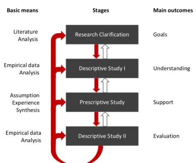
The Design Research Methodology (DRM) is a general research framework for conducting research with a prescriptive nature. Its main goal is to improve the current understanding of and develop support for design phenomena. Design describes “the process through which one identifies a need, and develops a solution—a product—to fulfil the need” (Blessing and Chakrabarti, 2009). DRM is comprised of four distinct phases, as illustrated in Fig. 2, and described in this thesis as a sequential process, but iterations among the different stages are possible. Staying flexible and “goal-driven” has proven to be positive in many cases (Blessing and Chakrabarti, 2009). It is also possible to focus on specific stages. This all depends on the intended outcome, as well as the time and funding available.
8
Fig. 2. DRM phases (middle), basic means for each stage (left), and main outcomes (right).
In stage one of DRM, called Research Clarification, the emphasis is primarily on understanding and describing the current situation and identifying the goal of the study. Necessary areas of investigation are also clarified, and preliminary success criteria are defined. This provides clarification upon which later stages can expound. The central outcome is a set of defined goals.
Stage two, called Descriptive Study I, is an elaboration of the first stage in which empirical studies are performed. It further improves the understanding of the current situation in clarifying which criteria are suitable. Suggestions are also made for the next stage, wherein the support is developed, specifically regarding which factors should be kept in mind. This stage’s outcomes are improved understanding and success criteria that can be useful when developing and evaluating the suggested support for the related design phenomena.
Stage three is called Prescriptive Study. This is where suggested support is developed with help from the first two stages. An evaluation of the actual support occurs as well to ensure that it consistently provides what it should. The main outcome is support.
The fourth and final stage, Descriptive Study II, is where the final evaluation takes place. This can be done by answering a series of essential questions regarding both the application evaluation (e.g., can the support be used, does it address the factors identified in the first descriptive study) and the success evaluation (e.g., does the support have the desired effects, does it lead to the desired situation). The primary outcome is an evaluation. Research Clarification Descriptive Study I Prescriptive Study Goals Understanding Support Evaluation Literature Analysis Empirical data Analysis Assumption Experience Synthesis Empirical data Analysis
Basic means Stages Main outcomes
9
Comprehensively performing all DRM stages is a tall order. However, this is not a necessity. Blessing and Chakrabarti (2009) described seven possible types of research depending on the preconditions and results sought (see Fig. 3). For instance, instead of performing a comprehensive study where literature research is supported with an empirical study, one can opt for the review-based approach. In a review-based approach, the time and resources available depict the completion of a stage. This can play a negative role in the study’s validation and verification, though.
Fig. 3. Possible DRM research types (iterations are omitted, and the backwards arrows point to continuations after each phase has finished).
2.2 Action research
Action research has grown out of a necessity to produce practical and applicable knowledge for social and organizational problems where rigorous positivistic science has limited applicability (Susman et al., 1978). A core reason for the limitations of positivistic science is that the subjects (social systems or organizations) are inhomogeneous with time, which affects replicability (an essential part of positivistic science; Checkland and Holwell, 2007). To understand the problems and corresponding solutions within these environments, action research proposes that the researcher takes an active role in drawing objective knowledge from the situation he/she observes. It resembles problem-solving activities as performed in day-to-day life, but when used as a research method, emphasis lies on systematism, clear definitions of the frameworks used, the method/model under investigation, and the area in which it is applied (Checkland and Holwell, 2007), as well as reflections supported by other researchers’ conclusions.
Research
Clarification DescriptiveStudy I PrescriptiveStudy DescriptiveStudy II
1. Review-based 2. Review-based 3. Review-based 4. Review-based 5. Review-based 6. Review-based 7. Review-based Comprehensive Comprehensive Comprehensive Comprehensive Comprehensive Comprehensive Comprehensive Comprehensive Comprehensive Review-based Review-based Initial Initial Initial Comprehensive Review-based Review-based Initial/Comprehensive Comprehensive
10
Within the Nordic countries, action research (as a form of research where researchers and practitioners work together) is also denoted as interactive research (Aagaard Nielsen and Svensson, 2006, p. 143). Svensson et al. (2002) described interactive research as a type of action research in which the researcher and practitioner work together in contrast to at, with, or for. It is also commonly defined as a way of enabling a mode of knowledge creation (Mode II; Gibbons et al., 1994) driven by usefulness in specific contexts, often relating to multiple academic disciplines and with elements of social responsibility.
2.3 Empirical data collection
Interviewing is a research technique often utilized to collect qualitative data. There are three types of interviews: structured, unstructured, and semi-structured. Depending on the level of structure in the interview, participants have a varied amount of freedom regarding which topics to discuss and in what order. Structured interviews have a set of questions defined prior to the interview, and these are asked in the same order in each interview. Unstructured interviews, on the other hand, allow the questions’ answers to influence where the interview goes. Unstructured interviews thus emphasize the perspective of the participant (Williams, 2002).
Questionnaires comprise a similar technique mainly used to collect quantitative but also qualitative data. They can be formed by questions of different types, such as factual, opinion, closed, and open (Williams, 2002).
2.4 Evaluation
To ensure that a study is of good quality, its results need to be evaluated. In design science, conducting scientifically acceptable evaluations is difficult because of their stochastic nature (they can increase the probability of improving something but do not guarantee it) and the sheer number of influencing variables (Buur, 1990), not to mention that design processes are inhomogeneous with time (i.e., they change over time). An experiment in which proposed design methods are tested in real-world settings often requires access to a company and its resources, as well as to its employees’ time and compliance to try new things, both of which most companies are not willing to share or accept on first contact. In addition, many design methods require initial investments, though profit might not come until several years later. All these aspects (and more) make evaluation that complies with natural science criteria implausible. Instead, other methods need to be employed.
Evaluations of design methods and research can be made, for instance, in accordance with the validation square (Pedersen et al., 2000), as in Raja (2019); the
11
DRM’s suggested questions (Blessing and Chakrabarti, 2009); Olesen’s (1992) five criteria, as in Poorkiany (2017) and André (2019); or Buur’s (1990) logical verification and validation through acceptance criteria. These methods overlap to a large degree, as they all separate verification and validation and focus on logical consistencies and acceptance in academia and industry. This thesis relies on Pedersen’s validation square (Pedersen et al., 2000) because it is the most elaborate evaluation tool and encompasses most of the others’ criteria, as detailed below.
2.4.1 Validation square
The validation square assesses verification and validation separately, which are defined in terms of internal consistency and the justification of knowledge claims, respectively (Barlas and Carpenter, 1990). This tool includes four aspects to consider and six criteria that should be supported (see Fig. 4).
Fig. 4. Validation square, adapted from Pedersen et al. (2000). The four aspects are:
• Theoretical structural validity – general structural soundness.
• Empirical structural validity – appropriateness of the example problems used to verify the method’s usefulness.
• Empirical performance validity – the example problems’ performance.
• Theoretical performance validity – performance beyond the example problems. Each of these aspects is associated with one or two criteria that are also indicated in Fig. 4. These criteria are:
Theoretical structural validity Theoretical performance validity Empirical structural validity Empirical performance validity (1, 2) (3) (4 ,5) (6) Supports Procedure
12
1. Acceptable construct validity – Are the constructs academically accepted? 2. Acceptable method consistency – Are the constructs logically put together? 3. Acceptable example problems – Are the example problems similar to what others
have reported for the constructs? Do the example problems represent what the method is meant to address? Can the example problems support a conclusion? 4. Accepting the method’s usefulness for the example problems – Does the method
achieve its intended purpose in the example problems?
5. Accepting that usefulness is linked to method application – Did the combination of the suggested constructs cause the outcome? Are there alternative explanations?
6. Accepting the method’s use beyond the example problems – Are criteria 1–5 admissible?
As Pedersen et al. (2000) described, case examples are not used as sampling points in a statistical experiment to support generalization. Instead, each case example is treated separately as an example supporting analytic generalization, as outlined by Yin (2018).
2.5 Applying the research approach
This research’s general approach was formed according to the DRM, which divides the necessary work into four distinct phases. Fig. 5 displays the basic means, publications, and research question(s) that each of this research’s phases concerned. The work is organized top to bottom and conforms best with research type 5 in Fig. 3, from its review-based Research Clarification phase to its comprehensive Descriptive I and Prescriptive phases and initial Descriptive II phase. As the work progressed, continuous refinements were made to previous phases. In particular, the necessary areas of concern from the Research Clarification phase expanded as new topics of interest were identified through literature reviews and interactions with industry actors and other researchers.
13
Fig. 5. Overview of DRM phases and their relationships with publications and research questions.
During the Research Clarification phase, a literature review was the basis upon which the research proposal was composed. In addition, the research project goals at the time were reviewed and the general focus defined per each research question.
In the Descriptive I phase, nine interviews were performed at three Swedish industrial companies. The results were presented and discussed in Paper I. Interviews were used to clarify the research topic from an industrial point of view and identify the challenges in an objective manner. In other words, three case examples were investigated through interviews to gain an initial understanding from an industrial point of view, not as a statistical experiment to garner a complete or general understanding of the industry state of practice. If the topics under investigation were well-known beforehand, a structured interview approach would have been applied, but a varying degree of flexibility was allowed instead. All interviews were recorded, transcribed, categorized, and summarized. A technical review was also performed to grasp the technical capabilities and restrictions with respect to the research in the Descriptive I phase. These results formed a list of criteria for improvement that guided the initial Prescriptive phase and provided a foundation for the evaluation in the Descriptive II phase. The results were also published in Paper I.
In the DRM’s Prescriptive phase, two studies of two separate action research characteristics were performed:
1. The first study assessed tool insert development automation and involved gathering and analyzing company-specific documentation, recording
Research Clarification Descriptive Study I Prescriptive Study Research questions Paper I & II
Paper III, V, & VI Paper IV & VII Literature review
Project goals review Interviews Technical review Action Research Conceptualization
Basic means Stages Main outcome
Descriptive Study II Questionnaire
Critical analysis Thesis
Research questions RQ 1 & 2 RQ 1, 2, & 3 RQ 3
-14
practitioners at work, collaborating with those practitioners, and collecting their reflections. This study’s results were presented in Paper III. A conceptualization was also completed to initiate the development of a framework meant to describe how product model extensions can be used to support the successful development, implementation, and maintenance of multidisciplinary DA. This was done by analyzing the results gathered at this point and formalize it in Paper IV.
2. The second action research study examined the integration of design for additive manufacture in a multidisciplinary DA system. It involved frequent visits to a company for access to company-specific software tools, models, and documentation, as well as collaborating with practitioners and gathering their reflections. These results were mainly expressed in Paper V. Following this study, an explorative study was performed that revealed how the prototype developed in the second action research study could be improved in terms of system transparency using visual programming. These results were presented in Paper VI. One final conceptualization study was performed in which the framework from Paper IV was further developed by analyzing the additional results that had been gathered. This was presented in Paper VII.
Finally, in the Descriptive II phase an evaluation was initiated and supported by empirical data from an open questionnaire in which the respondents were allowed to answer the questions in their own words (in contrast to choosing from a selection of answers) and their answers underwent a critical analysis using Pedersen’s criteria, as outlined in section 2.4.1. That evaluation appears in section 6.5.
15
3 Frame of Reference
This research strove to develop the DA field to support product development with more efficient and effective computer-based product modeling to enable customization. Below is a frame of reference within the relevant fields, ending with a summary including research opportunities (see Fig. 6 for an overview).
Fig. 6. Overview of the essential (dark blue) and related (light blue) concepts and research fields for the development of the main research field (green), together with
the central research topic (black).
3.1 Multidisciplinary design automation
DA can be considered a knowledge management approach for engineering design where knowledge is codified and stored to promote its utilization (McMahon et al., 2004). This knowledge can be represented explicitly in constraint networks, objected-oriented programming, CAx, procedural or declarative rules, among other
16
representation schemes (Rigger et al., 2018), or implicitly as induced knowledge from a larger data collection (McMahon et al., 2004). DA is primarily concerned with representing the general “how” and “what” of design tasks in design processes so that it can be reused (in contrast to, e.g., “why”). This includes simple information handling (e.g., moving information from one system to another) and knowledge processing (e.g., using information to make decisions and produce new information; Cederfeldt and Elgh, 2005). Multidisciplinary DA means that the processes within multiple disciplines, such as classical mechanics, fluid dynamics, thermodynamics, design, and manufacturing, are taken into consideration. This adds to the complexity because each discipline has its own objective, usually uses its own set of tools, and is commonly divided into its own organizational unit.
A system can be defined as “a regularly interacting or interdependent group of items forming a unified whole” (Merriam Webster, 2020). DA systems usually comprise computerized items that support engineers in a design process phase (Johansson, 2011). DA systems are developed by formalizing and systematizing design processes that result in a collection of pre-planned reusable assets. Most engineers encounter repetitive work and implement some level of automation (LoA), such as drawing templates and spreadsheet scripts, and DA systems can vary in the degree to which human interaction is required. However, to be considered an automation system, a system must perform an activity.
With this broad definition, it can be argued that any software system utilized by engineers is also a DA system. Looking at a word processor, such as the one in which this dissertation is written and that is widely used in engineering design processes, much of the work, especially in text-editing, would have required manual labor in the past (e.g., erasing and rewriting text). Thus, to some extent this argument might be true, and it might be more relevant to discuss the levels and types of automation. One study (Parasuraman et al., 2000) presented an LoA scale from 1 (no assistance given) to 10 (the system is completely autonomous and ignores the human agent), along with four types of automation: information acquisition, information analysis, decision selection, and action implementation. Fig. 7 shows how a system can vary in its LoA and type.
17 High Low High Low High Low High Low Information
Acquisition Information Analysis SelectionDecision ImplementationAction
Lev el o f Aut om at io n System A
Fig. 7. Types and levels of automation in a system (Parasuraman et al., 2000). Product configuration is one effective approach to enabling customization (see section 3.4.2). From a DA perspective, configuration systems have been developed and applied extensively for this purpose, but their requirements in the underlying product representation make them infeasible on their own to organizations that require some engineering for each customer order. Knowledge Based Engineering (KBE) and procedural systems are not restricted to the same limitations but lack the same level of flexibility and generality. KBE and procedural systems could be used in combination with configuration systems, where for instance the product representations are generated from a customer-oriented front-end configuration system; both are illuminated in more detail below, though the current research has completely concentrated on the latter.
3.1.1 Configuration systems
Configuration systems are usually modeled using constraint-programming languages (Hvam et al., 2008) in terms of constraint satisfaction problems (CSP; Rossi et al., 2006; Zhang, 2014). CSP represent a product as a constraint network that consists of variables, their respective domains, and constraints (Dechter, 2003). Variables are objects that can take on one or several values, a domain is a list of objects used to define possible variable values, and constraints impose limitations on the values that a variable or variables can be assigned. Constraints can be described explicitly using relations or implicitly using, for example, arithmetic expressions or logical operators. Modules are a central part of product configuration systems that can be defined as “a limited part of a product with a well-defined function and a well-defined interface to the remaining parts (modules) of the product” (Hvam et al., 2008). A module is also represented as a collection of variables that make sense to the product being
18
configured: for instance, a frame, wheels, seat, drivetrain, shift system, and steering wheel for a bicycle.
Configuration systems are often characterized as either customer-oriented or technical. Customer-oriented configuration systems are typically simplified and keep the number of variables and their domains low since customers are not expected to have deep technical knowledge. Technical configurators impose many challenges to classical CSP, such as dealing with an unknown number of components, user preferences when there are multiple solutions, explanation services when constraints are propagated (Rossi et al., 2006), active and non-active variables (dynamic CSP), and managing continuous variables (Aldanondo et al., 2003).
Configuration systems, in CSP terms, are appealing due to their flexibility and generality. However, solving large and complex CSP often requires detailed product knowledge to formulate heuristics or possible simplifications (Falkner et al., 2011) and rely on a pre-defined set of variables, domains, constraints, and functions that make them challenging for organizations following an engineer-to-order (ETO) approach to adopt (Zhang, 2014; Sylla et al., 2018). KBE systems, as discussed below, comprise another approach developed from a common background in knowledge-based systems (or expert systems) but with a different emphasis.
3.1.2 KBE and procedural systems
KBE systems and configuration systems both originated from artificial intelligence research. More precisely, they are special developments or applications of knowledge-based systems (or expert systems) derived for efficient product configuration (Hvam
et al., 2008; La Rocca, 2012). Whereas configuration systems focus on modeling
products in terms of modules and constraints, KBE concerns capturing and reusing product and process knowledge. For this reason, KBE systems do not require completely pre-defined modules. This fundamental difference makes them more applicable to organizations with an ETO-oriented business approach, but they are not without their own challenges.
KBE systems require geometry creation and manipulation, as well as data processing capabilities that are not available in conventional knowledge-based systems (La Rocca, 2012). In addition, KBE systems have a tendency to become “black boxes” of which only special system developers know the inner workings, which affects the reuse of the knowledge they contain (Verhagen et al., 2012). The definition of KBE has evolved from being centered around object-oriented programming, CAD, and artificial intelligence technologies (Chapman and Pinfold, 2001) to the “application of knowledge to automate or assist in the engineering task” (Baxter et al., 2007). Whether or not that includes systems in which knowledge is offered procedurally is not clear.
19
Methodology and software tools oriented to knowledge-based engineering applications (MOKA) are the result of a research project whose main aim was to reduce “the amount of up-front investment and risk associated with the development of KBE applications” (Stokes, 2001). MOKA provides two levels of knowledge representation: a general and easy-to-understand model called the Informal Model, and a second model that allows the represented knowledge to be plugged into a KBE package called the Formal Model. The Formal Model has two distinct elements. The first describes the “what” of a product, including aspects such as assembly, parts, materials, behavior, functions, how it is manufactured, and its shape and size. The second involves, in a general sense, what the design process does, how it does it, and why, but it does not itself evaluate, select, analyze, or facilitate any part of the design process. Verhagen (2013) analyzed MOKA and other KBE development methodologies and outlined a number of shortcomings, such as investigations of the nature and consequence of changes in knowledge, the adoption of methodologies within research publications, and quantitative evaluation capabilities. A new methodology then emerged called KNOMAD (knowledge capture and identification of knowledge change, normalization, organization, modeling and implementation, analysis, and delivery) to address these shortcomings.
Procedural systems embody knowledge in a sequence of pre-determined steps in contrast to conventional KBE languages (e.g., Knowledge Fusion in Siemens NX), where this is determined during runtime (La Rocca, 2012). In this research, the focus was mainly the implementation/realization phase of procedural DA systems as supported by object-oriented and visual programming, as well as some constraint- and rule-based representations within CAD models.
3.2 Computer-based product modeling
Modeling is the general process of producing a representation of “the construction and working of some system of interest” (Maria, 1997), that is, a model. Models can be used to, for instance, predict system performance under different scenarios that would otherwise be impossible or expensive to do with the system itself. Following the same reasoning, product modeling is about producing representations of products (i.e., product models) to predict its performance with respect to customer requirements, safety aspects, manufacturability, environmental impact, or other characteristics of interest. In addition, product models help create information and instructions for physical production, logistics, and disposal/recycling.
The introduction of computer-controlled machine tools, or computer numeric control (CNC), in the 1950s first identified a need for computer-based product design representation (Shah and Mäntylä, 1995). For this reason, computer-based product modeling was initially concerned with geometry models and has since evolved to
20
include other aspects of product realization, such as function, behavior, manufacturing, and disposal/recycle.
Today, product modeling research focuses on computer-based product modeling driven by the increased efficiency and effectiveness of product development. Among other things, researchers are seeking ways to associate and integrate information between product life cycle stages, capture and represent the rationale (why and how) behind solutions, and enable distributed modeling (Lyu et al., 2017). This thesis addresses DA, which examines how to construct models concerning the “how” behind solutions. Automation models are separated from specific product models because they include information about the process of producing, usually parts-of, product models.
Below are more detailed descriptions of modeling approaches and the content of geometry, product, and automation models.
3.2.1 Geometry model
Product geometry representation and processing was first developed in the late 1950s and early 1960s to, among other things, model numerical part models to drive numerically controlled machines (developed in the early 1950s) and, later on, other engineering disciplines such as pre- and post-processing with the finite element (FE) method (Shah and Mäntylä, 1995). There are several different types of geometric models (Shah and Mäntylä, 1995):
• graphical
o wireframe models.
o mainly for 2D drawings based on graphical primitives and their attributes, e.g., a line with thickness and style (dashed, solid, etc.). • surface
o used for more complex geometry in, e.g., turbine blades and car bodies. o usually parametric functions in terms of polynomials.
o usually a combination of curve segments where three continuity conditions are possible (point, tangential, and curvature).
o approximate curves for easier modeling, e.g., Bézier, B-Splines (generalized Bézier curves), rational parametric curves and non-uniform rational B-Splines (NURBS).
• solid
o developed to address problems with graphical models, e.g., lack of robustness, incompleteness (devil’s fork), and limited applicability. o three large classes: decomposition (primitive object types “glued”
together, e.g., meshes for finite element analysis), constructive (constructive solid geometry, primitive object types operated through set
21
theory, e.g., union, difference, intersection), and boundary (B-Rep, higher dimension objects given as boundaries of lower-level dimensions, e.g., faces with edge boundaries).
Current geometric models within mechanical engineering are commonly represented by using CAD systems as CAD models, which are commonly enhanced with parametric, feature-based, and rule-based modeling. Feature modeling can be thought of as extensions to solid modeling (began around 1970) in response to their inability to model non-geometric information, to propagate design changes on a part level (in contrast to geometry), and integrate with downstream applications. Knowledge-based product modeling further expanded CAD modeling capabilities by incorporating product knowledge in terms of rules, which enabled the use of technologies developed for artificial intelligence, such as knowledge-based systems. Integrated product modeling incorporates geometric, feature-based, and knowledge-based modeling methods in one product model to support integrated product development. More about features, rules, and integration appears in section 3.3.
3.2.2 Product model
The product model concept is ambiguous in academic discourse (Weidmann et al., 2017). Here, for instance, are three separate definitions of a product model:
1. A “formal specification defined by information modeling techniques” created to represent product data in a “complete and unambiguous way to facilitate the storage, sharing, and exchange of information, as well as searching for information” (Isaksson et al., 2000).
2. “Describes the ‘WHAT’ of an engineering product” and “contains all the knowledge that describes the product itself,” including geometry, product structure, behavior, function, constraints, and how it is manufactured (Stokes, 2001).
3. “The logical accumulation of all relevant information concerning a given product during the product life cycle. They store the information in forms of digital product model data, and are equipped with access and manipulation algorithms” (Krause et al., 1993)
In this thesis, a product model is a digital model of a product that includes everything that is modeled during the computer-based product modeling process. This means that anything from the product’s requirements, functions, behaviors, forms, constraints, and how it is designed and manufactured to how it is sold, used, disposed, or recycled can be included. This definition differentiates itself from the first one above because it does not necessarily have to be a complete, unambiguous, and
22
formally defined specification. These are instead seen as wanted characteristics, which are often challenging to adhere to. In contrast to the second definition, product models can contain the “how” and “why” of a product as well. A typical feature-based CAD model, for instance, contains the modeling operations describing “how” it came to be. The third definition makes a distinction between relevant and irrelevant information. Arguably, all information modeled during the process was relevant at some point for some reason, and if it is not removed, it is also included in the model (e.g., as a part of the design rationale).
Product models are developed incrementally and iteratively as part of a product modeling process that in turn is part of a product development process. From a practical perspective, this means that engineers create product models that are developed and used in and even after a process via different views of the information contained within the model. It is usually composed of many smaller models that can share information between themselves as well with external models, such as manufacturers or businesses (see Fig. 8). For instance, the manufacturing process model shares how the product will be manufactured and also both more generic and detailed models in the manufacturing system.
Fig. 8. An example of different model types in a digital product model. Standard product models, such as ISO 10303 (also known as the standard for the exchange of product model data, or STEP), concern the representation of product data to enable interoperability throughout the product life cycle and long-term storage and retrieval. These models were developed by studying design output representation in
Product model Requirement model Manufacturing model Geometric model Function model Behavior model Rationale model Design model 0..*
23
the form of geometric (Fenves et al., 2005) to non-geometric information, such as geometric dimensioning and tolerance. Core product model2 (CPM2), briefly described in Fenves et al. (2008), is another standardized product model that further expands the scope to support information such as function, behavior and material.
3.2.3 Automation model
Automation models can be considered part of an organizational database supporting knowledge representation and reuse, such as design repositories (Szykman et al., 2000) and design platforms (André et al., 2017). Automation models represent design knowledge, or information about the “how” and “what” of a product model, in a machine-interpretable manner (and preferably human-interpretable as well). Knowledge within product modeling is commonly divided into product and process knowledge (Chandrasegaran et al., 2013). Product knowledge refers to that which is already known about the product model, and the representation is therefore sometimes denoted as product meta-model. Process knowledge can then be categorized in many ways: for instance, considering levels of abstraction/granularity, product life cycle stages, or design, manufacturing, and business (Chandrasegaran et al., 2013). Within the DA context (specifically KBE), Stokes (2001) defined the design process model as a model that describes “the steps that realize a Product Model.”
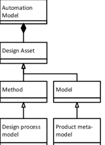
This thesis uses the construct design asset (see Fig. 9). Design process models are also denoted as methods and include descriptions of parts of product models, that is, representations of the steps that realize product models or parts of product models. Product meta-models are denoted as models and together with methods form design assets, or pre-defined computer-based reusable resources. Finally, automation models are collections of design assets.
Fig. 9. Automation model and the relations between the different constructs used.
Method Design Asset Automation Model Model Product meta-model Design process model
24
3.3 Extended product model
Product models are commonly constructed with various CAx tools, spreadsheet applications, word processors, text editors, among other software tools. These tools all use their own information models that handle different data types for different purposes. It is then up to the users to utilize the modeling techniques available to form a coherent product model. Extended Product Models (EPMs) as presented here are all about enabling an efficient and effective information flow within computer-based product modeling, where some activities are supported or completely operated by automation systems. They can be visualized as information “sockets” that enable different disciplines to connect or relate constituents of their automation model (see Fig. 10). Below in sections 3.3.1 and 3.3.2 are introduction to related work.
Fig. 10. The Extended Product Model (EPM) concept.
3.3.1 Features and annotations
The integration of DA and CAD models has a long history going back to feature-based CAD in the 1970s (Shah and Mäntylä, 1995) and annotations in 2006 (McMahon and Davies, 2006), both with the goal of creating more semantic geometric DA models, as well as capturing design rationale and product life cycle information. Annotations are also applicable to other types of models, such as spreadsheets and text files.
Features within computer-based product modeling are ambiguous. Implementations in commercial CAD software are mostly shape macros, such as
Production Reliability Performance Product model Extended Product model
25
extrusion, fillet, and rotation, and are limited in semantic, multi-view, and free-form feature modeling (Bronsvoort et al., 2006). Mandorli et al. (2020) recently discussed the lack of semantic feature support in commercial systems and presented semantic hole features. Within academia there are discussions about physical and information features (Sanfilippo and Borgo, 2016), geometry-bound and non-geometry-bound features (Li et al., 2020), and “commonalities and variabilities” modeling developed in product line software engineering (Gacek, 2002; Romero et al., 2019). Due to its general definition outside the field of product modeling as “a prominent part or characteristic” (Merriam-Webster, 2020), it is not surprising the feature construct is used within other fields as well for various purposes. Within this thesis, the original definition of features by Shah and Mäntylä (1995) is used where features are used to model more semantic geometric models:
“By features we mean the generic shapes or characteristics of a product with which engineers can associate certain attributes or knowledge useful for reasoning about that product. Features encapsulate the engineering significance of portions of the product geometry and, as such, are applicable in product design, product
definition, and reasoning about the product in a variety of application such as manufacturing planning.” (Shah and Mäntylä, 1995)
Feature properties can include generic shapes (topology and geometry), parameters (e.g., for independent dimensioning, constraint, location, orientation, and derived value), methods (e.g., location/attachment, orientation, geometric construction procedures, recognition algorithm, validation rules or procedures, and inheritance rules or procedures), constraints relating to dimensions, location, and orientation (possibly between several features), tolerances, and non-geometric attributes (auxiliary data such as text and scalar or vector formats, including material properties or complete procedures for cost estimation or process planning).
Annotation within product modeling is an approach inspired by document mark-up that serves as an extension to feature-based modeling to capture a design’s multiple feature-based representations (McMahon and Davies, 2006). Document mark-up is an approach that adds tags to document data to separate logical elements and specify the processing functions to be performed on those elements (Goldfarb, 1990). Similarly, in product modeling the idea is to separate logical elements (e.g., point, edge, face) and their processing functions from different views (e.g., machined face, drill hole, apply load, fixed boundary). One important distinction between annotations and features is that procedures are completely separated in the latter in contrast to the former. Several standardized languages used extensively for document mark-up: Hyper Text Mark-up Language (HTML; standard for documents displayed in web browsers), eXtensible Mark-up Language (XML), and Resource Description Framework (RDF). Standardized product models such as STEP also support
26
annotations, but their use varies (see section 3.3.2 for more information). Examples of annotations can be found within the model-based enterprise paradigm, which has adopted the model-based definition methodology (Miller et al., 2017). Instead of only replacing 2D drawings with 3D CAD models, model-based enterprise has been described as a way of supporting information consumption among organizational activities. Many of the examples found revolve around annotating 3D CAD models to make the geometry more comprehensive and, in this way, make the models more reusable (Trainer et al., 2016), as they are stored inside or outside the actual CAD model (Camba et al., 2014). Lightweight Model with Multi-layer Annotation (LIMMA) is another example that uses lightweight geometry representations to enable annotations inside or outside the CAD model (Ding et al., 2009).
Shah and Mäntylä (1995) introduced an important categorization of feature model creation that McMahon and Davies (2006) also used to discuss annotation: 1. Extracting features from solid models:
a. Interactively (interactive feature creation) – Originally developed for process planning, this is the simplest approach to implement. Interactive extraction requires manually grouping geometric elements and adding user-defined properties that can be supported by a pre-defined feature library with or without geometric element requirements.
b. Automatically (automatic feature recognition) – Involves the development of algorithms to identify pre-defined generic features, e.g., determining feature parameters (hole diameter, pocket depth) or extracting specific geometric entities, as in Stolt (2008).
2. Creating solid models with features (Design by feature):
a. Destructively (destructive solid geometry) – Starting with initial solid model representing raw material and using machining features, possibly simultaneously creating a manufacturing plan.
b. Synthesis (synthesis by design features) – Adding and removing material with or without a raw material model to start.
c. Procedurally – Pre-defining features with procedures to create, modify, copy, and remove geometry for one-way change propagation.
d. Declaratively – Modeling implicit constraints with general constraint propagation algorithms to enable two-way change propagation (e.g., a hole in a body can have its depth changed by changing the thickness of the body, and the thickness of the body can change if the hole’s depth is changed).
27
3.3.2 Interoperability
Interoperability between heterogeneous models is a major challenge and cause of much inconsistency and ambiguity in a product model. Interoperability can be defined as the “degree to which two or more systems, products or components can exchange information and use the information that has been exchanged” (ISO/IEC/IEEE, 2017), as well as addressed by developing standards and tool integration (Li et al., 2020).
Standardization is theoretically the most effective solution to interoperability since with a standard, the number of translators required is only as many as the number of tools. Analogously, it would be more efficient for everyone to learn one common language (e.g., English) instead of everyone learning each other’s. Even though elaborate standards do exist (e.g., STEP and CPM2), there are challenges to implementing them in practice, as that depends on the software vendor. Software vendors might find that implementing standards conflicts with their other objectives because completely standardized representation makes the transition from one tool to another easier (Szykman et al., 2001). However, as users demand more standardized representation over time, the software vendors also gradually implement them.
Integration is the other approach to enabling software interoperability. This requires either software vendors creating custom bridges between tools or merging multiple tools into one. It is an approach that solves individual interoperability issues more efficiently than the standardized approach, all with no risk to customer retention.
3.4 Product development
Product development is a decision-making process that produces a model of a product as opposed to a physical one as within production. On a general level, product development can be viewed from four main perspectives: marketing, organization, engineering design, and operations management (Krishnan and Ulrich, 2001). Each perspective involves different levels of product detail and utilizes various knowledge sources. These knowledge sources are what this thesis denotes as disciplines, which are also commonly referred to as fields of study. Examples from the engineering design perspective are classical mechanics, fluid and thermodynamics, and design.
Collaboration between disciplines is crucial, as they work with the same product model but follow different agendas, often resulting in conflicting aspirations. Digitalization is a trend that manifests itself in product development. For instance, to increase their competitive potential, manufacturing companies have introduced several different types of computer simulations to improve their engineering design process’s effectiveness and efficiency. As indicated in Petersson et al. (2015), where 77 people answered a survey, about 35% of them used computer-based design analysis and 28% expected to do so in the future. Simulations can, compared to physical tests,