IN
DEGREE PROJECT MATERIALS DESIGN AND ENGINEERING,
SECOND CYCLE, 30 CREDITS ,
STOCKHOLM SWEDEN 2019
Nitrogen Removal in a
Vacuum Tank Degasser
An Investigation on the Nitrogen Removal
Performance
BJÖRN T. I. AHLIN
KTH ROYAL INSTITUTE OF TECHNOLOGY
Abstract
The impending change of processes at SSAB Oxelösund due to the HYBRIT project, where the blast furnace and LD converter are to be replaced with an EAF will have a significant impact on the manufacturing of steel in Oxelösund. One issue that will arise is the nitrogen content in the steel. Sources claim that the nitrogen content in steel from an EAF route is substantially larger, 60-70 ppm, than in steel from a blast furnace and LD converter route, which have a nitrogen content of around 25 ppm. Therefore, the nitrogen removal capabilities of SSAB Oxelösund’s vacuum tank degasser were to be examined. Industrial trials were performed where the amount of slag during vacuum treatment was lowered. The intention was that half the amount of slag removed prior to vacuum treatment and later completely slag free. This was performed in an attempt to increase the effective reaction area, where nitrogen removal occurs. Due to some practical problems with the steel mill, the industrial trial were unfortunately cut short. Consequently, only trials with half the amount of slag were performed and compared to existing process data for standard praxis. Also, nitrogen removal calculations based on the industrial data were performed. A parameter representing the overall reaction rate, which is dependent on effective reaction area was obtained, validated and subsequently applied to a future case scenario. The results indicate that the reduction in slag amount does have the desired effect, increasing the said area and increasing the rate of nitrogen removal. However, the sample size is not nearly sufficient enough to determine this definitively. The conclusions reached were that the facility does have the possibility to decrease the increased nitrogen content down to reasonable levels, around 20-30 ppm. Albeit, an increase in vacuum treatment time is probably required. Another conclusion was that surface active elements, such as oxygen and sulphur greatly reduce the nitrogen removal. Therefore, efforts should be taken to remove these elements prior to vacuum treatment. In addition, it was established that the effective reaction area is of great importance for a successful nitrogen removal. Therefore, actions to maximise this area should be taken. Finally, it was stated that further research is necessary in order to fully understand nitrogen contamination prevention- and removal techniques.
Sammanfattning
Förändringar till följd av HYBRIT projektet kommer påverka SSAB Oxelösunds stålverk. Masugn och LD konverter skall ersättas med ljusbågsugns teknologi. Ett problem till följd av detta är kvävehalter i stålet. Enligt litteraturen är kvävehalterna betydligt högre i stål tappat från en ljusbågsugn. Med kvävehalter runt 60-70 ppm jämfört med stål tappat från en LD konverter som har kvävehalter kring 25 ppm. Därför krävdes en undersökning kring kvävereningpotentialen för SSAB Oxelösunds vakuum tank avgasare. Industriella experiment med minskad slaggmängd jämfört med standard praxis blev utförda. Detta utfördes med tanken att minskad slaggmängd skulle ge en större effektiv reaktionsarea. Intentionen var att utföra försök först med halverad slaggmängd följt av slaggfria försök. Dock, på grund av produktions praktiska problem vid verket blev försöken avbrutna. Som en följd av detta blev bara försök med halverad slaggmängd utförda och jämförda med processdata från standard praxis. Kvävereningsberäkningar på historisk processdata utfördes. En parameter som representerade genomsnittlig reaktionshastighet, vilken beror på den effektiva reaktionsarea blev erhållen, validerad och senare applicerad på ett hypotetiskt framtida scenario. Resultaten indikerar att minskad slaggmängd har en positiv inverkan på den effektiva reaktions arean och till följd av detta även en positiv inverkan på kväverening. Dock är för få försök utförda för att kunna fastställa detta. De slutsatser som dras är att vakuum anläggningen vid SSAB Oxelösund har möjligheten att, med förlängd vakuumbehandlingstid, rena de ökade kvävehalter till nivåer runt 20-30 ppm. Ytterligare slutsatser var att ytaktiva element, såsom syre och svavel, i stålet har en stor negativ påverkan för kväverening. Samt att den effektiva reaktionsarean är av stor betydelse för kväverening. Därför bör ansträngningar tas för att minska koncentrationen av ytaktiva element samt att försöka göra den effektiva reaktionsarean så stor som möjligt. Slutligen fastställdes det att ytterligare studier är nödvändiga för att öka kunskapen kring förebyggande tekniker och reningstekniker för kväveföroreningar i stål.
Table of Contents
1 Introduction ... 1
2 Background ... 4
2.1 Nitrogen’s role in steel ... 4
2.2 Sources of Nitrogen and Prevention Techniques ... 4
2.3 Elements Effect on Nitrogen in Steel... 5
2.4 Thermodynamics and Kinetics regarding Nitrogen Removal ... 7
2.4.1 Nitrogen Removal Rate and Removal Calculations ... 7
2.5 Practical Aspects on Nitrogen Removal ... 8
2.5.1 Carbon Boil ... 9
2.5.2 Vacuum Degassers ... 9
2.5.3 SSAB Oxelösund’s VTD, Layout and Process... 10
3 Method... 12
3.1 Industrial trials ... 12
3.2 Hypothetical future scenario ... 13
4 Results ... 15
4.1 Results- Industrial Trials ... 15
4.1.1 Solubility of Nitrogen ... 15
4.1.2 Heat 1 ... 17
4.1.3 Heat 2 ... 17
4.1.4 Standard praxis ... 17
4.1.5 Validation calculations of β values ... 18
4.2 Hypothetical case ... 19 5 Discussion ... 20 5.1 Industrial Trials ... 20 5.1.1 Solubility ... 20 5.1.2 Heat 1 ... 20 5.1.3 Heat 2 ... 21
5.1.4 Standard Praxis Discussion ... 22
5.1.5 Summary of Industrial Trials ... 24
5.2 Hypothetical Case ... 24
5.3 Error sources and Limitations ... 25
5.3 Environmental and Economic impact. ... 25
6 Conclusions and Recommendations ... 27
8. Acknowledgements ... 29 9. References ... 30
1
1 Introduction
In an effort to reduce their impact on the climate, SSAB in collaboration with LKAB and Vattenfall AB have introduced the HYBRIT project. The main objective of HYBRIT is to develop a fossile-free steel production by replacing carbon and coke with hydrogen and electricity from renewable sources [1]. As a result of the conversion, SSAB will reduce their massive carbon dioxide (CO2) emissions.
Consequently, replacing the emissions with, obviously, less harmful emissions of water.
HYBRIT will have a great impact on the process at SSAB’s plant in Oxelösund. As of today, the mill produces steel from iron ore via a blast furnace route. The obtained crude iron is processed in a torpedo, for sulphur removal. Furthermore, the iron is transported to a Linz-Donawitz (LD) converter, where the carbon content in the steel is reduced by oxygen blowing. Subsequently, resulting in an effective nitrogen removal through a carbon boiling. After decarburization, the process is followed by secondary metallurgical processes. At first, the liquid steel is homogenized in a stirring station. Especially, with regards to alloying elements that has not dissolved during the LD process. The homogenization is closely followed by treatment in two different routes, either a vacuum route in a Vacuum Tank Degasser (VTD) or in a Ladle Furnace (LF). Finally, the metallurgical process in the plant is finished with continuous casting in either billets or blooms. After casting, the produced steel is further processed both in house with diffusion furnaces and various metal forming processes as well as shipped to customers. The process route as of today is shown in figure 1.
Figure 1. Process flow chart of steel production at SSAB Special Steels, Oxelösund
As a result of the HYBRIT project, the idea is to replace the four processes, coke plant, blast furnace, torpedo treatment and LD converting with a hydrogen reduction furnace and an Electric Arc Furnace (EAF). The proposed changes in the process route is presented in figure 2.
2
Figure 2. Proposed changes on the process flow [2]
Following the melting process in the EAF, the process route is the same as in figure 1. The proposed changes will, according to HYBRIT, lower SSAB’s CO2 emissions in Sweden from 1,600 kg per tonne
of crude steel down to 25 kg per tonne. Additionally, they claim that there will be a reduction in the necessary energy of approximately 1,300 kWh, from 5,466 kWh for the blast furnace route in comparison to 4,090 kWh for the HYBRIT process [2]. Indeed, these reductions would be of great benefit environmentally, globally with regards to the climate change. Also, the removal of the coke plant will probably result in an improvement in air quality for the residents of the Oxelösund municipality.
However, change is often associated with exciting challenges. For instance, as the blast furnaces are replaced in Oxelösund the main raw material for the EAF will in the beginning be steel scrap. Later it will be replaced by direct reduced iron (DRI), probably in the form of Hot Briquetted Iron (HBI). One of the challenges is that the nitrogen content for scrap-based metallurgy is increased in comparison to blast furnace metallurgy [3]. Present day steelmaking at Oxelösund obtains a nitrogen content of around 25 ppm, which is considered as low. Whereas, the nitrogen content obtained for a scrap-based EAF process is in the region of 60-100 ppm [3]. Such an increase can pose a serious problem for a steel producer that manufactures plates, due to the deleterious effect of nitrogen that will be handled in later sections of the thesis. Therefore, efforts must be taken in order to counteract this increase.
3
The aim of this study was to determine if SSAB Oxelösund’s VTD process has the capacity to reduce the high nitrogen content that a scrap-based EAF process yields. Mainly, the theory was that reduced amount of slag during vacuum treatment should increase the metal/gas interface where nitrogen removal is possible [4]. Consequently, improving the nitrogen removal potential. The industrial trials were performed at SSAB’s plant in Oxelösund, more specifically at their vacuum tank degasser station. In addition, industrial trials were complimented with a hypothetical case.
The paper’s outline will be to present relevant background information regarding nitrogen removal. This is followed by a presentation of industrial trials with corresponding results. As well as, a presentation of the hypothetical case also with corresponding results. Furthermore, the obtained results are discussed with cross reference to the relevant background. Moreover, the discussion serves as a foundation for drawn conclusion and lastly interesting areas to delve deeper into is presented.
4
2 Background
As previously stated, this study is focused on studying the nitrogen removal in a VTD. In this section, the reader will be presented relevant background information necessary to understand the role of nitrogen in steelmaking. Is nitrogen only deleterious to the steel or can it serve a purpose? Sources of nitrogen and how to remove it from the steel. Also, considerations regarding different parameters that affect the removal of nitrogen has been made.
2.1 Nitrogen’s role in steel
Nitrogen in steel can be regarded as both an unwanted element that has a deteriorating effect on the material properties and as an alloying element. Negative aspects of nitrogen include, but are not limited to, a reduced plasticity and weldability. Nitrogen as an alloying element can be beneficial for many properties, such as the corrosion resistance, creep strength and toughness [5]. Examples of applications where nitrogen is used are Nitrogen Bearing TRIP duplex stainless steels, where expensive alloys such as nickel and molybdenum are substituted with nitrogen and manganese [6]. Also, nitrogen can be used as a replacement element for carbon in tool steels [7]. As for the steel produced at SSAB Oxelösund, nitrogen is considered as an unwanted element and efforts are taken to minimize the content in the steel.
2.2 Sources of Nitrogen and Prevention Techniques
The nitrogen content in steel is affected by numerous factors. One major contributing source is interaction with air. If steel interacts with air, nitrogen pick-up can take place. Therefore, slags are used as a protective agent, which shields the liquid steel. The amount of pick-up from air is influenced by so called surface active elements, such as oxygen and sulphur. If the content of these surface active elements are high the pick-up is low. Likewise, if the situation is turned around pick-up is greater [8].
The interaction with air is most likely to occur during metal transfer, e.g. tapping steel from one vessel to another. The liquid steel cannot be covered by a slag layer at these instances. Therefore, other measures must be taken in order to minimize nitrogen pick-up. For example, during continuous casting the steel is tapped using a submerged entry nozzle. However, this approach is not possible while tapping steel from a converter to ladle. Steels tapped from converters are usually deoxidized by additions of either silica or aluminium. Thus, reducing the amount of surface active elements in the steel. Consequently, this leads to an increase in nitrogen. Researchers have shown that if the steel is tapped without deoxidation the pick-up of nitrogen is reduced [9].
Anyhow, the steel has to be deoxidized at some point in the process chain, preferably prior to secondary metallurgical processes. Therefore, addition of deoxidizers are often placed inside the ladle prior to tapping. As a result, during tapping the molten stream is protected from nitrogen through the oxygen content and deoxidation is performed in the ladle.
Also, the tapping spout is of importance for nitrogen pick-up during tapping. If the spout produces a stream of liquid steel that is turbulent, it will result in a greater surface area where the steel encounters air compared to a spout that produced a laminar stream. The flow of the streams can be correlated to the condition of the spout, wear and tear on the spout will increase the turbulence in the stream [10].
One other source of nitrogen is contaminated gas used for stirring. Leaks in the system providing gas to the converters and ladles that allows air to infiltrate the gas piping, can result in nitrogen increases in the steel or retard the effects of nitrogen removal during vacuum treatment [11].
According to Allertz et al. [12] some authors claim that nitrogen pick-up is possible from the slag. They claim that the nitrogen content in slags are high enough to cause a reintroduction of the removed nitrogen. However, these studies have made experiments in graphite crucible. Therefore, a slag saturated with regards to carbon is obtained. Conversely, Allertz et al. has shown that the nitrogen capacity in slags with low carbon content, which often is the case in steelmaking, is too low in order to facilitate
5
nitrogen pick-up [12]. The mentioned study used crucibles of similar material as the ladles used in the industry. Consequently, their results reflect an industrial setting more than the earlier works.
Another factor influencing nitrogen content in steel is the raw material used. Different raw materials contain varying amounts of nitrogen.
2.3 Elements Effect on Nitrogen in Steel
It is widely known that dissolved elements in liquid steel affect the melts behaviour. Elements can affect, but are not limited to, the melting temperature, viscosity and, with most interest for this study, the solubility of various elements. Moreover, it is not only elements that affect nitrogen in steel. Indeed, factors such as temperature and pressure are also of importance for the nitrogen content.
The solubility of nitrogen in liquid iron at 1600 °C is shown as a function of pressure in figure 3.
As mentioned, elements dissolved in the steel has an effect on the nitrogen solubility. The elements effect can be described by an interaction parameter that affect nitrogen’s activity coefficient. In figure 4, the effect of some alloying elements on nitrogen solubility at 1600°C and at a pressure of 1 atm is presented. Also included in the figure is elements affect on nitrogens activity coefficient under similar conditions.
6
Elements such as oxygen and sulphur, which are dissolved in steel are called surface active elements. As the name suggest, they interact with the surface of the steel. Since, nitrogen removal is dependent on adsorption into gas bubbles, the presence of surface active elements hinders nitrogen from reaching the reaction area. Thus, limiting the purge of nitrogen [13]. A study by Turkdogan [14] calculated the retarding effect on nitrogen removal that different sulphur content has, which can be seen in figure 5.
Figure 5. Vacuum treatment times for different initial sulphur contents [14].
Figure 4-a) Elements effect on the nitrogen solubility in steel. b) Elements effect on nitrogen's activity coefficient. Both at 1600°C and a pressure of 1 atm [23]
7
According to Yu et.al [13], temperature have a great impact on how the surface active elements behave during vacuum treatment. At higher temperatures, the fraction of surface active elements present at the gas/metal interface is decreased. Thus, increasing the effective reaction area where nitrogen removal is thought to occur.
However, a high content of these surface active elements can be beneficial to steel manufacturing, if the concentration is high at the right time. For example during tapping from a converter to a ladle. High concentrations of these elements during tapping reduces the nitrogen pick-up from surrounding atmosphere. Therefore, it is of great interest to investigate deoxidization routines to control the nitrogen content in the steel.
Temperature is also of importance for nitrogen solubility in steel. A study by Sheng et.al. [5] showed that the nitrogen solubility in liquid steel is decreased with increased temperature. Furthermore, they also showed the pressure dependency of nitrogen solubility. Their results for a Fe-Cr-Mn-V-N alloy, with 4.0 wt% Chromium content is shown in figure 6.
2.4 Thermodynamics and Kinetics regarding Nitrogen Removal
Nitrogen is a gaseous element, which has a diatomic molecular structure. Moreover, it is a proven fact that nitrogen, similarly to hydrogen and sulphur obeys Sievert’s law for solubility in molten steel. Removal of nitrogen requires that dissolved nitrogen in the steel is precipitated as gas. A reaction highly dependent on pressure. The reaction is shown in equation 1.
𝑁𝐹𝑒 = 1 2⁄ 𝑁2(𝑔) (1)
The precipitated gas is absorbed by other gaseous elements, such as carbon monoxide and argon and subsequently flushed out of the steel, an in-depth description of this phenomena can be found in later sections.
2.4.1 Nitrogen Removal Rate and Removal Calculations
Removal rate of nitrogen in a gas stirred vacuum facility is dependent on three factors, namely i) the mass transfer of nitrogen in steel to gas-metal interface, ii) chemical reaction of nitrogen at the interface and iii) mass transfer of nitrogen gas from the interface to gas phase. Although, the latter is not
Figure 6. Nitrogen solubility as a function of temperature at different nitrogen partial pressures
8
considered as a controlling step, due to the belief that the transfer is fast. Therefore, the removal rate is controlled either by mass transfer and chemical reaction of nitrogen or both combined. The determining factor is the content of surface active elements. Mass transfer rate in liquid steel if the content is high, chemical reaction at interface if the content is low [13].
The removal rate of nitrogen can either be describe by a first order differential equation, as seen in equation 2.
𝑑[%𝑁]
𝑑𝑡 = −
𝑘𝜌𝐴
𝑀 ([%𝑁] − [%𝑁]𝑒𝑞) (2)
where [%N] is concentration of nitrogen in the steel, k is the mass transfer coefficient, ρ is the density of the steel, A is effective reaction area and [%𝑁]𝑒𝑞 is the theoretical equilibrium content of nitrogen.
Or by a second order differential shown in equation 3.
𝑑[%𝑁] 𝑑𝑡 = − 𝑘′𝜌𝐴 𝑀 ([%𝑁] 2− [%𝑁] 𝑒𝑞 2 ) (3)
where 𝑘′ is the second order mass transfer coefficient.
In order to calculate the removal rate one must decide which of the two differentials that is valid. According to Steneholm et al. [15] the factor determining is the concentration of the surface active elements oxygen and sulphur. For a combined concentration under 80 ppm equation 2 is valid, conversely, over 80 ppm equation 3 is valid [15]. Furthermore, the author’s used an overall rate constant defined as β, since the effective reaction rate area was not possible to determine. See equation 4.
𝛽 =𝑘𝜌𝐴
𝑀 (4)
Since, Sievert’s law is applicable the theoretical equilibrium content can be determined through equation 5.
[%𝑁] =𝐾𝑁
𝑓𝑁(𝑝𝑁2)
1/2 (5)
where 𝐾𝑁 is the equilibrium constant for the reaction, 𝑓𝑁 is the activity coefficient, and 𝑝𝑁2 is the
partial pressure of nitrogen. The assumption that partial pressure of nitrogen is equal to total pressure is made in order to make the calculations.
By the use of well-known thermodynamic relations equation 5 can now be written as follows:
[%𝑁] =(𝑝𝑁2)1/2
𝑓𝑁 𝑒𝑥𝑝 ( −∆𝐺𝑁0
𝑅𝑇 ) (6)
Additionally, Wagner’s equation is used to determine the activity coefficient and by solving equation 2 the following relation is obtained
−𝑙𝑛 (%𝑁𝑡−%𝑁𝑒𝑞
%𝑁0−%𝑁𝑒𝑞) = 𝛽𝑡 (7)
where %𝑁𝑡 is nitrogen content after time t, %𝑁0 is the intitial concentration of nitrogen. The author’s
showed in their study that nitrogen removal calculations with this expression, applied for their given steel grade, yielded results comparable to industrial experiments [15].
2.5 Practical Aspects on Nitrogen Removal
The practical aspects of nitrogen removal can, however, be rather simplified divided in to two areas, namely atmospheric pressure and low-pressure treatments (vacuum). Both treatments depend on gaseous elements that transport nitrogen through the melt up to the interface metal-atmosphere/slag. The two approaches are described in the following sections.
9
2.5.1 Carbon Boil
Steel must per definition contain some amount of carbon. Mostly, the carbon content during steelmaking is rather high during earlier stages in the process chain. These high levels of carbon are reduced by decarburization, often in converters. Decarburization is performed by oxygen blowing, usually by lance, in to the melt. The oxygen encounters dissolved carbon and a reaction resulting in carbon monoxide (CO) is obtained. As CO is formed, the local equilibrium is changed. The partial pressure of nitrogen is lowered in these local regions, promoting equation 1. The formed nitrogen gas adsorbs into the CO gas bubbles. The obtained gas bubbles is transferred to the metal-slag interface, with the aid of buoyance and stirring, and subsequently removed from the melt. This phenomena is called a carbon boil.
However, as with all processes everything is a compromise. The oxygen blown into the melt is not restricted to only carbon, also valuable alloying elements, such as Cr will be oxidized. As a result decarburization for stainless steels are more complex than for regular carbon steel. Hence, the development of Argon Oxygen Decarburizing (AOD) converters. Where, the oxygen is blown in combination with argon (or nitrogen) at different ratios depending on process time in order to minimize oxidation of valuable alloying elements and maximize the oxidation of carbon.
Decarburization processes will increase the temperature of the melt. Consequently, additions of coolants are required, often in the form of scrap. Besides its cooling effect scrap can also increase the nitrogen content for the final product. Especially, if the scrap melts in latter stages of the process. In order to produce low nitrogen steels, one must avoid heavy scrap and instead use light scrap or other sources such as DRI for cooling purposes [16].
2.5.2 Vacuum Degassers
The theory behind vacuum treatment of steel is that the solubility of nitrogen is lowered due to decreased pressure. Thus, promoting the reaction shown in equation 1, dissolved nitrogen forms nitrogen gas bubbles. However, decrease in pressure is not enough to facilitate nitrogen removal. Therefore, inert argon gas stirring is applied. As vacuum is applied and argon gas is injected, the atmosphere in the chamber is changed from air at atmospheric pressure to an argon atmosphere at low pressures. Nitrogen dissolved in the steel that encounters the gas bubbles will adsorb into the bubbles and subsequently be flushed from the melt. Removal of hydrogen is performed in the same manner. Also, sulphur removal is linked to this process. However, sulphur demands a slag layer that has the capacity to collect the sulphur.
As mentioned earlier, the nitrogen removal is affected by pressure. As shown in figure 4 elements have great impact on the solubility of nitrogen, hence, different steel grades have different nitrogen solubilities. Therefore, depending on what content of nitrogen that is acceptable for the steel grade, the vacuum pressure required to obtain acceptable concentrations differ from steel grade to steel grade. At SSAB Oxelösund a vacuum pressure just under 2 mbar is often considered as sufficient. However, as low pressure as possible should be desired. For instance, Wu et al. states that pressures as low as 0.3 mbar at 1600 °C for 50 minutes is needed in order to reach a nitrogen content of 10 ppm, with an initial nitrogen content of 18 ppm [3] for their investigated steel grade.
One of the controlling steps of nitrogen removal is the chemical reaction at the interface between steel and gas phase. It is clear that a bigger interface surface leads to a faster nitrogen removal. There are several factor that can affect the size of the interface area. For instance, the injected gas flow rate. A higher flow rate results in more bubbles in the steel, where nitrogen can adsorb into the bubbles. In addition, a high enough flow rate will disturb the slag layer and cause the formation of an open eye, where the steel is exposed to the atmosphere in the chamber. This will result in a great interface area where nitrogen removal is possible. However, too high gas flow may cause skulling. Also, pressure has a great impact on the interface area. As the bubbles in the plume moves upward in the melt, the bubbles will increase in size due to ferrostatic pressure. In combination with the low pressure of vacuum treatment the bubbles will rupture, thus greatly increasing the interface area [17].
10
Time is also an important factor for nitrogen removal. Similar to other reactions, nitrogen removal is not an instantaneous process. The vacuum treatment at SSAB Oxelösund aims for a process time at around 20 minutes. However, depending on the requirements for the produced steel the time can vary a lot. For instance, Steneholm et al. showed that for their specific steel grade a vacuum treatment time of 10 minutes was sufficient [15]. Conversely, for ultra-low nitrogen content treatment times up to 50 minutes might be needed [3].
There exist several different vacuum treatment facilities that can be used. Basically, they are developed after the same theory, namely a decreased pressure and stirring with inert gas. The variations of these facilities are developed with regards to different theories on factors that can improve vacuum treatment processes. These include Tank Degassers (detailed information in a later section), RH-degassers, ladle furnaces equipped with vacuum lid and stream degassers. The difference in configuration of the various degassers are shown in figure 7.
Figure 7. Different designs of vacuum treatment facilities [18].
There are several factors determining whether the equipment will suffice. Especially, the facility’s ability to seal tight is of great importance. Leakage of surrounding atmosphere into the chamber or into the argon gas pipe are major issues that must be avoided. If the there is a leakage into the argon gas, the available sites for dissolved nitrogen to adsorb into are already filled. If there is a leakage into the chamber, from the lid or other openings, the ability to achieve a sufficiently low pressure is basically impossible. Therefore, the facilities require consistent maintenance and leakage searches.
2.5.3
SSAB Oxelösund’s VTD, Layout and Process
SSAB Oxelösund previously had the possibility to use vacuum on their ladle furnace station. However, in an attempt to improve their vacuum treatment an investment on a dual VTD station were made in 2009. It is an equipment consisting of three stations with different lids, two vacuum lids and one ladle refining furnace (LRF) lid. Despite having two vacuum lids, there is only one steam driven vacuum pump. As a result, there is only possible to perform vacuum treatment on one ladle at the time. Adjacent to the tank degasser, a mechanical rake for slag skimming is positioned. The LRF lid is basically a standard ladle furnace, equipped with electrodes. The ladle’s have two porous plugs in the bottom, which facilitates bottom stirring with argon gas. The ladles are connected to the tank and the gas is provided by pipes via the tank to the ladle. The argon flow rate is often set at around 200 l/min and with a possibility of boosting these values in the beginning of the treatment. This to obtain spout eye, once the spout eye is obtained the operators, with visual aid, lowers the flow and try to maintain a stirring operation that has an spout eye but is not to violently stirred so that skulling may appear.
As can been seen in figure 1, the molten steel is transferred from the LD converter to secondary treatment stations. The first stop is the TN station, where the steel is homogenized by a stirring action. The stirring
11
allows undissolved alloying elements from the LD converter to dissolve. After the stirring the liquid steel is transferred to the VTD station. Firstly, a slag skimming is performed. This because of detrimental elements, such as vanadium, in the slag might be reintroduced to the steel during vacuum treatment. Secondly, the molten steel is transferred to the tank and put into the LRF. In the LRF, slag additions, alloying and heating procedure is carried out. The amount of necessary alloying and heating is evaluated with aid from sample analysis from the T-N station. When the slag is fully liquid and the desired temperature is reached samples are taken and the tank is moved into the vacuum position, where a subsequent vacuum treatment of around 20 minutes is performed. After vacuum treatment, the tank is moved into the LRF station again and final adjustments regarding alloying and heating are performed. Also, another series of sampling of temperature and steel composition are performed. Lastly, the ladle is transferred from the tank and taken to the continuous caster. The plant aims for a total treatment time at the VTD station at approximately ninety minutes.
12
3 Method
This section describes the method used in this study. At first, the industrial trials that were carried out is described. The industrial trials are then followed by theoretical calculations that depict a plausible future scenario for the steel mill.
3.1 Industrial trials
As stated earlier, the industrial trials were conducted at SSAB Special Steels Oxelösund. Specifically, at their VTD station. The trials were greatly assisted by the practical knowledge of the skilled operators working at the station. The intention was to perform multiple heats, minimum 20, where half were supposed to be with 50 % slag and the other half slag free. In addition, the later trials, the slag free trials were supposed to have increased nitrogen content up towards 60 ppm prior to vacuum treatment. The results obtained were compared with data from standard praxis at the steel plant.
First and foremost, a specific steel grade was chosen for the trials. There was one major factor taken into account for the choice of steel grade, namely, its tolerance for a high nitrogen content. Therefore, the chosen steel grade was a SSAB DOCOL PHS 2000, which is a boric press hardening steel for the automotive industry. The composition of the steel grade is shown in table 1.
Table 1. Composition of DOCOL (siffror)
Grade C [wt%] Si[wt%] Mn[wt%] P[wt%] S[wt%] Cr[wt%] B[wt%] Nb+Ti[wt%] DOCOL 0.38 0.35 1.50 0.025 0.005 0.35 0.005 0.2
Moreover, one aim for the company was that the trials had as small impact on the daily production as possible. In order to minimize the impact, the production planning team at SSAB was consulted and a reasonable time slot in the production schedule was chosen.
As described in section 2.5.3, the VTD station has two vacuum tanks. In order to maintain consistent conditions, it was decided to only use one tank for the trials, namely tank 1. In addition, tank 1’s shorter distance to the slag removal machine was also preferable.
The steps taken for the trials differed somewhat from the standard VTD treatment at the plant. Altogether, two changes were made to the process. Consequently, more samples were needed to see the effect of the changes, a total of three extra sampling occasions were needed. To begin with, the liquid steel was transferred to the VTD station and the standard procedure of slag-removal and addition as well as alloying was performed. At this point, the first alteration was made, namely, heating to a temperature of about 10-15 degrees higher than normal. The operators experience determined when the wanted temperature probably was obtained. The heating process was closely followed by a sampling sequence consisting of temperature, oxygen and steel samples, denoted A. In the case of temperature measurements, the bath height is also registered in order to facilitate steel sampling. The oxygen activity measurement were performed with CELOX. However, the CELOX equipment cannot measure oxygen activities if the content is below 2 ppm.The temperature and oxygen results were noted. In the case of steel samples, the samples were collected and marked with heat number and a letter denoting the order of sampling.
In the next step, the ladle was transferred to the slag removal station and approximately 50 % of the slag was removed. The slag amount removed was determined by the expertise of the operators. Directly following the slag removal another sampling sequence took place, with the same procedure as previously stated, denoted B. After the sampling the ladle was transferred to vacuum tank 1 and a standard vacuum procedure commenced.
13
The vacuum treatment was closely followed by another sampling sequence, denoted C. During the trials, process data was monitored and logged. The process data included vacuum pressure, time under vacuum and argon flow rate.
The three collected steel samples were later sent for analysis at the chemistry lab at SSAB Oxelösund. Subsequently, the samples were analysed with regards to composition. The composition was determined through a combined analysis with optic emission spectroscopy (OES) and combustion analysis. These analysis are performed according to standards ASTM E415-17 [19] and ASTM E1019-11 [20] respectively. The combustion analysis were performed on carbon and nitrogen, whereas, all other elements were analysed by the aid of OES. The obtained compositions were analysed.
Moreover, the composition of the steel prior to vacuum treatment was used for nitrogen removal calculations based on the equations listed in section 2.4.1. The composition used was from a chemical analysis, analysing a whole range of elements. However, due to corporate confidentiality, the full composition of the steel cannot be disclosed. Also, the process parameters pressure, vacuum time and temperature were needed. Furthermore, the activity coefficient calculations required interaction parameters. The used interaction parameters were for a conidition at 1600°C and were obtained from the book ‘Treatise on Process Metallurgy’ [21]. Also, values for the standard Gibbs free energy calculations that were needed was taken from Steneholm et al. [15]. Some assumptions regarding the process parameters were necessary. The partial pressure of nitrogen was assumed equal to total pressure and the pressure was set to 1.5 mbar for all calculations. Additionally, calculations at a lower pressure were also made, namely 0.3 mbar. Also, the assumption that no heat was lost during vacuum treatment was used. By using all these parameters, the β parameter, the overall rate constant from equation 4 was derived.
The industrial trials also comprised of an investigation on how the vacuum treatment as of today, with the praxis mentioned in section 2.5.3 and how it affects nitrogen content in the steel. The compositional analysis results and temperature measurements were retrieved from SSAB’s logged data for sampling closest before and after vacuum treatment. The results obtained are presented in the results section and are used for comparison with regards to relevant background information and for heats 1 and 2. In addition, investigations on a different steel grade were also performed. By applying the same reasoning regarding nitrogen removal calculations as for heats 1 and 2, a β-value for standard praxis was derived.
The solubility of nitrogen in the steel was calculated with Thermo-Calc. The thermodynamic database TCFE9 was chosen. Furthermore, the calculations required input data regarding the composition of the steel. The thermo-calc simulations were performed in such a way that it represented a vacuum tank degasser. Meaning, that the steel is put in a chamber and the surrounding pressure is lowered. Therefore, the composition input was specified with regards to compositional analysis taken before vacuum treatment. This in order to represent the solubility of nitrogen in the ingoing steel.
All the relevant result from the trials as well as calculations are presented in the results section.
3.2 Hypothetical future scenario
As stated in the introduction the nitrogen content in the steel is increased for scrap-based metallurgy in comparison with blast furnace metallurgy. In this section a theoretical case is presented with corresponding calculations.
First and foremost a steel grade to investigate had to be chosen. For comparison the same steel grad as in the industrial trials were chosen. Moreover, a steel grade that has higher alloying contents was also of interest. Two different steel grades were used for the hypothetical case. The same steel grade as for the industrial trials, a low alloyed SSAB steel grade, and a high alloyed steel grade. In table 2, the maximum concentration, in weight-percent, of elements for the two steel grades are presented. The presented compositions are for finished products. The compositions applied to calculations differs
14
somewhat from the presented maximum concentrations. For instance, sulphur content is substantially larger, around 0.030 wt%.
Table 2. Maximum concentrations of elements for the investigated steel grades all values in wt%
Grade C[wt%] Si[wt%] Mn[wt%] P[wt%] S[wt%] Cr[wt%] Ni[wt%] Mo[wt%] B[wt%] DOCOL 0.38 0.35 1.50 0.025 0.005 0.35 nn nn 0.005 Hardox 0.26 0.70 1.60 0.025 0.010 4.50 1.50 0.60 0.005
The time required for nitrogen removal for the future case were calculated with the obtained β values from the industrial trials in combination with equation 7. In addition, an initial and final nitrogen content in the steel had to be specified. Nitrogen contents of 60 and 20 ppm respectively was chosen after discussions with representatives at SSAB Oxelösund. Also, the temperature was set to 1600 °C and the pressure to 1.5 mbar. Calculations with a pressure of 0.3 mbar was also made. There was two mean β values obtained from the industrial trials, one for half slag practice and one for standard praxis. Also, calculations with maximum and minimum β values were performed. Lastly, a calculation that determined the necessary β value for removal of nitrogen from 60 ppm to 20 ppm was calculated. This gives an indication on how large the effective reaction area has to be. The results were compared.
15
4 Results
At first this section presents results from the industrial trials. Following, the results regarding the hypothetical case are presented.
4.1 Results- Industrial Trials
The industrial trials consisted of two heats, heats 1 and 2, and an investigation on the standard praxis for vacuum treatment. Results from the chemical analysis only shows the nitrogen concentration and concentration of surface active elements. The results will be shown in the following order: Solubility of nitrogen in the steel followed by heat 1 and 2 and lastly standard praxis.
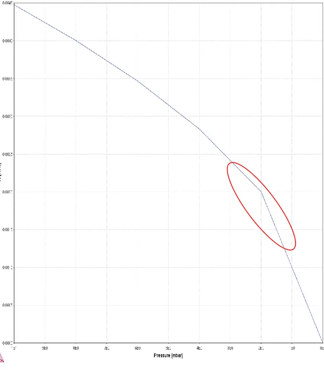
4.1.1 Solubility of Nitrogen
The nitrogen solubility in liquid steel at 1600°C for the steel grade investigated in the industrial trials is shown as a function of pressure in figure 8. The pressure interval is from 10 mbar down to 0 mbar.
Figure 8. Nitrogen solubility as a function of pressure for the steel grade used in the industrial trials, from 10 mbar and decreasing
16
The red ellipse highlights the interesting area between 3 mbar to 1.5 mbar. Noteworthy, is that the nitrogen solubility at 2 mbar, from where process time is logged, is around 0.0020 wt% (20 ppm). The subsequent calculations were performed at 1.5 mbar, where it can be seen that the solubility is around 0.0015 wt% (15 ppm). Still, at higher pressures, around 3 mbar, the nitrogen solubility of the Docol steel grade is sufficiently low (25 ppm) to facilitate nitrogen removal in the extent desired.
The nitrogen solubility in the hypothetical future scenario steel grade, is shown in figure 9. The solubility is for 1600 °C and as a function of pressure.
Figure 9. The nitrogen solubility for the hypothetical future steel grade as a function of pressure. From 10 mbar and decreasing
Similarily to the Docol steel grade, the hardox steel grade also show a decreasing solubility of nitrogen with decreasing pressure. However, as the red ellipse highlights, the nitrogen solubility is larger for the Hardox grade. As can be seen at around 2 mbar the nitrogen solubility is around 0.003wt% (30 ppm). Interesting to note is that to reach a solubility of 20 ppm nitrogen the pressure would have to be decreased to under 1 mbar.
17
4.1.2 Heat 1
Compositional analysis and temperature measurements for heat 2 are shown in table 3. In which, A denotes before slag skimming, B after slag skimming and C after vacuum treatment.
Table 3. Results from heat 1, A is before slag skimming, B is after slag skimming and C is after vacuum treatment
Sample T [℃] N [ppm] S [ppm] O [ppm]
A 1581 40.6 33 2.0
B 1562 36.1 32 2.4
C 1537 34.6 23 -
The vacuum time under 2 mbar was logged at 20 minutes and the mean pressure achieved was 1.4 mbar. The lowest achieved pressure was 1.2 mbar.
The mean gas flow rate of argon was logged at 30 l/min and 29 l/min from the two porous plugs respectively during the vacuum treatment under 2 mbar. Resulting in a total use of argon gas used at 1200 l.
Calculations with equations 2-7 stated in section 2.4.1 and data from heat 1 gave the following β value 7.86E-05 for 1.5 mbar and 5.33E-05 for 0.3 mbar.
4.1.3 Heat 2
Compositional analysis and temperature measurements for heat 2 are shown in table 4. In which, A denotes before slag skimming, B after slag skimming and C after vacuum treatment.
Table 4. Results from heat 2, A is before slag skimming, B is after slag skimming and C is after vacuum treatment
Sample T [℃] N [ppm] S [ppm] O [ppm]
A 1590 22.6 16 -
B 1587 22.1 14 -
C 1550 19.4 4 -
The vacuum time under 2 mbar for heat 2 was 19 minutes. The mean pressure under 2 mbar was logged at 1.7 mbar, with the lowest point at 1.5 mbar.
The mean gas flow rate of argon during the vacuum treatment under 2mbar was 132 l/min and 167 l/min for the two porous plugs respectively. Resulting in a total use of 5,681 l.
Calculations with equations 2-7 stated in section 2.4.1 and data from heat 2 gave the following β value, 2.15E-03 for 1.5 mbar and 1.95E-04 for 0.3 mbar.
The mean β value for heat 1 and 2 was calculated to 1.12E-03 and 1.24E-04 for 1.5 mbar and 0.3 mbar respectively.
4.1.4 Standard praxis
Process data, vacuum time, temperature, analysis results and temperature for the same steel grade as heats 1 and 2 from normal practice at SSAB Oxelösund are shown in table 5. The values are in weight percent in ppm, vacuum time under 2 mbar in minutes, temperature in Celsius and pressure in mbar.
18
Table 5. Process data from standard vacuum treatment
Charge no Nbefore vacuum [ppm] Nafter vacuum [ppm] Sbefore vacuum [ppm] Safter vacuum[ppm]
tvacuum,2mbar[min] Tbefore vacuum [°C] Plowest [mbar] 31889 27 25 17 13 18 1566 1.24 31890 21 19 20 5 20 1598 0.83 31906 24 23 18 5 19 1585 1.12 31907 26 25 34 6 19 1564 0.97 32798 27 22 21 5 19 1573 0.90 32799 24 19 21 5 18 1597 0.90 32800 27 21 19 5 19 1584 0.90
The equations stated, eq. 2-7, in section 2.4.1 gave the calculated β values shown in table 6.
Table 6. Calculated β values for 1.5 mbar and 0.3 mbar for standard praxis
Charge no 31889 31890 31906 31907 32798 32799 32800 β1.5 mbar 1.96E-04 6.17E-04 1.25E-04 1.05E-04 6.27E-04 1.23E-03 8.27E-04
β0.3 mbar 9.96E-05 1.36E-04 5.44E-05 4.92E-05 2.63E-04 3.39E-04 3.26E-04
The obtained mean value of β was calculated to 5.33E-04 for 1.5 mbar and 1.81E-04 for 0.3 mbar.
The relevant process data for the Hardox steel grade is presented in table 7. The values are in weight percent in ppm, vacuum time under 2 mbar in minutes, temperature in Celsius and pressure is given in mbar.
Table 7. Process data for the Hardox steel grade
Charge no Nbefore vacuum [ppm] Nafter vacuum [ppm] Sbefore vacuum [ppm] Safter vacuum [ppm]
tvacuum,2mbar[min] Tbefore vacuum [°C] Plowest [mbar] 30457 98 63 27 7 28 1603 - 37892 49 36 19 5 28 1612 1.05 27407 63 54 24 12 24 1601 1.03 37445 48 43 30 6 18 1595 1.09
The obtained β values for the Hardox grade are presented in table 8.
Table 8. Calculated β values for the Hardox steel grade
Charge 30457 37892 27407 37445 β1.5 mbar 3.90E-04 4.77E-04 1.89E-04 2.24E-04
β0.3mbar 3.08E-04 2.52E-04 1.33E-04 1.35E-04
Where a mean β value for 1.5 mbar was calculated to 3.20E-04 and 2.07E-04 for 0.3 mbar.
4.1.5 Validation calculations of β values
The nitrogen and sulphur contents in the steel, before and after vacuum treatment are presented in table 9. In addition, the known times for vacuum treatment are also presented. Lastly, the calculated time using the mean β value from the standard praxis are shown.
Table 9. Results from validation calculations
Charge no Nbefore NAfter Sbefore Safter tvacuum, under 2 mbar[min]
19 36947 0,0027 0,0022 0,0021 0,0006 18 22 4 37916 0,0024 0,0022 0,0018 0,0005 6 10 4 37917 0,0021 0,002 0,0019 0,0005 6 8 2 38357 0,0041 0,0031 0,0007 0,0005 19 17 -2
4.2 Hypothetical case
The calculated times required for nitrogen removal at a pressure of 1.5 mbar are presented in table10.
Table 10. Results from nitrogen removal calculations at 1.5 mbar for the hypothetical case
Grade tβ-half slag [s] tβ-full slag [s]
Docol 2392 (40 min) 5009 (83 min) Hardox 1769 (29 min) 6163 (103 min)
In table 11 calculated nitrogen removal time at a pressure of 0.3 mbar is presented.
Table 11. Results from nitrogen removal calculations at 0.3 mbar for the hypothetical case
Grade tβ-half slag [s] tβ-full slag [s]
Docol 11609 (193 min) 7967 (133 min) Hardox 7693 (128 min) 4619 (77)
20
5 Discussion
In this section the results presented are discussed with reference to the relevant background information.
5.1 Industrial Trials
First and foremost, the number of trials consisted of only two completed heats, while the target was to reach around 20 heats. Unfortunately, due to undisclosed problems with the required equipment, the vacuum tank degasser, there was no possibility of fulfilling the wanted number of heats.
5.1.1 Solubility
The nitrogen solubility shown in figures 8 and 9 shows, not surprisingly, that the solubility is lowered significantly with a decrease in pressure. For the Docol steel grade shown inf figure 8, the nitrogen solubility decreases from around 45 ppm at 10 mbar down to 15 ppm at 1.5 mbar. Similiarily, the hardox steel grade exhibits the same behaviour, decreasing the solubility from around 65 ppm at 10 mbar down to around 25 ppm at 1.5 mbar. The solubility was also calculated for the nitrogen removal calculations with the use of sieverts law. The calculated nitrogen solubilities were consisten with the thermo-calc simulations.
Interesting is to look at the solubility at 2 mbar, which is the value SSAB Oxelösund uses as starting point for logging of deep vacuum treatment. For the industrial trials steel grade, it can be seen that the solubility is around 20 ppm, which is sufficiently low for most of the steels produced in Oxelösund. Conversely, for the future case steel grade the solubility is higher. At 2 mbar the solubility of nitrogen is around 30 ppm. As shown in figure 4, the nitrogen content increases with increased chromium content. Therefore, it is most likely that the high chromium contents is the reason for the high solubility value. Such a high solubility makes it problematic to reach a nitrogen content of 20 ppm, well impossible at a pressure of 2 mbar. As seen in figure 9, the pressure has to be in the region of 0.9 mbar in order to lower the solubility to wanted levels. Therefore, after consultation with representatives from SSAB, the calculations regarding the future scenario had a different end-value for nitrogen content, namely 30 ppm. As shown from the solubility graphs one might assume that the problem is solved. However, thermodynamics does not show the whole picture, kinetics play a big role as well.
5.1.2 Heat 1
As can be seen from results regarding heat 1 presented in table 3, the nitrogen removal during vacuum treatment is next to nothing, from 36.1 ppm to 34.6 ppm (4.16% decrease in nitrogen content). The low decrease in nitrogen content during vacuum treatment might be explained by several factors.
For instance, a level of sulphur of 32 ppm prior to vacuum treatment, is considered as a fairly high value. As stated in section 2.3, sulphur and oxygen are what is called surface active elements. The combined value of these elements prior to vacuum treatment amounted to 34.4 ppm, with sulphur as the dominant factor with 32 ppm. In order to facilitate a proper nitrogen purge, the surface active elements has to be reduced. The oxygen content after treatment was too low to register using CELOX measurements. Therefore, one can assume that the vacuum treatment has removed a sufficient amount of oxygen. Conversely, the sulphur content after treatment was still rather high, namely 23 ppm. Indeed, this indicates that the sulphur content in the liquid steel has not decreased enough during the allotted treatment time in order to facilitate an environment that facilitates nitrogen removal.
Previous studies have claimed that an increased temperature prior to vacuum treatment is beneficial for an improved nitrogen removal. Also, according to thermodynamics the solubility of nitrogen in molten steel is lowered at higher temperatures and should consequently be beneficial for nitrogen removal. For heat 1, maintaining a high temperature was difficult. As can be seen in table 3, the temperature decreased by a massive 19°C during the slag skimming step. In comparison, the temperature for heat 2 only dropped 3°C for the corresponding step and time. As a result, the low temperature might be a reason for the poor nitrogen removal. The following investigation regarding the temperature drop showed that the
21
ladle used during heat 1 was a new ladle. As a consequence, the ladle did not contain any latent heat from previous charges and was not sufficiently warm. Therefore, the temperature gradient between molten steel and ladle was too high and consequently the ladle stole heat from the molten steel.
As mentioned, air infiltration might cause problems. One can see from the achieved vacuum pressure that leakage into the tank chamber should not be a factor influencing the process. However, air infiltration into the argon gas system might be the cause of the poor removal of the nitrogen. This might also explain the poor sulphur refining.
Also of interest, is the decrease in nitrogen content during the slag skimming from 40.6 ppm to 36.1 ppm. This result is very peculiar, since there is no reason for this decrease. The decrease is most likely due to a measurement error. Since, the only other explanation would be that the steel was not homogenized properly and an accumulation of nitrogen near the surface of the steel bath had occurred, and during the slag skimming, liquid steel just under the slag layer was removed. This is highly unlikely, because of the stirring performed in the TN-station. For this specific heat, the process time at the stirring station was twice as long compared to ordinary praxis. This because of a problematic charge that required additional process time at the VTD prior to heat 1.
Based on these considerations, the one might be inclined to think that a combination of a high sulphur content (23 ppm after vacuum treatment) and low ingoing temperature (1562℃) that is the reason for such a bad nitrogen removal for heat 1. However, a closer examination on the argon stirring shows interesting results. The argon flow rate is very low, around 30 l/min for each porous plug. Since the flow rate of gas is adjusted by the operators, based on visual examination of the obtained slag eye, the results are quite interesting when compared to heat two, that had a flow rate surpassing 130 l/min for each plug. As the refining of both sulphur and nitrogen was rather low, and the flow rate is very low, gives one reason to believe that the flow rate applied has not maintained a spout eye. Resulting in a very small effective reaction area, which is indicated by the β value obtained.
5.1.3 Heat 2
As for the nitrogen removal during heat 2, the nitrogen content had already reached very low value prior to vacuum treatment, namely 22.1 ppm. According to the study mentioned regarding nitrogen removal for ultra-low content of nitrogen [3], removal of nitrogen is more difficult the lower the content. Despite this, the vacuum treatment resulted in a decrease of 2.7 ppm, from 22.1 down to 19.4 ppm (12.2 % decrease in nitrogen content).
As can be seen from the results in table 4, the surface active elements, sulphur and oxygen are quit low. Sulphur levels both before and after are considered as low, 14 ppm and 4 ppm respectively. The oxygen levels were too low in order to give readings from the Celox measurements. These results indicate that the oxygen content is lower than 2 ppm during the whole process. Although, it might also be that the equipment used for measurements have malfunctioned. However, due to the good results with refining of both sulphur and nitrogen and the deoxidation praxis applied it is not unlikely that the oxygen concentration is below 2 ppm. The low concentrations of surface active elements, should according to the studies mentioned in section 2.3, elements effect on nitrogen in steel be very beneficial for nitrogen removal.
The achieved time under vacuum was sufficient for the produced product. However, based on the study by Wu et al. one might wonder what nitrogen content could have been reached with longer treatment time. The solubility diagram for the steel grade presented in figure 8, shows that at these small concentrations, under 20 ppm, the vacuum pressure applied is crucial in order to lower the concentrations.
As for problems with leakage, air infiltration, it is a factor that can be disregarded. Because, the results on nitrogen and sulphur removal indicates that there was sufficient number of available sites for adsorption.
22
The temperature during heat 2, did not decrease drastically during the slag skimming as for heat 1. A decrease of 3°C during the slag skimming is not, in any way, out of the ordinary. Also, a temperature of 1587°C at the start of vacuum treatment should be sufficient for nitrogen removal.
The argon flow rate during heat 2 was very high, almost 300 l/min. Such an argon flow rate will most likely sustain stirring conditions that results in the formation of spout eyes. As indicated by the β calculations, the flow rate combined with low contents of surface active elements results in an large effective reaction area
5.1.4 Standard Praxis Discussion
As mentioned earlier, the compositional analysis and temperature measurements on the industrial data are samples that are taken closest before and after vacuum treatment. This does not necessarily mean just before or after vacuum treatment. Also, there might also have been additional process steps taken, such as heating and alloying in between. This is slightly problematic, since the results obtained can be misinterpreted. It might be so that the nitrogen removal has been very successful, but further treatments have added nitrogen content.
As can be seen from the results, there are no oxygen values presented. This because under normal circumstances at the steel mill, there are no oxygen measurements during the VTD process. However, since the liquid steel is deoxidised, with either aluminium or silicon, one can assume that the dissolved oxygen content is very low and consequently has no effect on nitrogen removal.
The nitrogen content in the steels, were lowered for all cases. However, some experienced a lower rate of removal. The decrease in nitrogen content ranged from the poorest removal with an 3.8% decrease (26 to 25 ppm) for charge 31907 to an 22.2 % decrease (27 ppm to 21 ppm) for charge 32800. This can be correlated to several different sources.
As for surface active elements, sulphur and oxygen might have had an effect on the results. As mentioned earlier the oxygen content should not pose a problem, due to the deoxidisation praxis. However, the sulphur content might be an issue. Even though, the sulphur content is not that high (17 ppm) before vacuum for charge 31889, the content after is significantly higher (13 ppm) compared to the other cases (5-6 ppm). There is almost no sulphur refining at all. This in combination with a poor nitrogen removal, indicates that there is a possibility of contaminated argon gas. If the argon gas piping has any leakages, the available sites for refining is occupied thus retarding the nitrogen and sulphur refining. The other cases had similar ingoing sulphur content (around 20 ppm), with the exception of 31907 that had a sulphur content of 34 ppm. However, the sulphur refining of the other cases was good, giving similar final sulphur content of about 5 ppm. These low levels of sulphur should indicate good conditions for nitrogen removal. As seen from the results, a low outgoing sulphur content is no guarantee for a good nitrogen removal.
Vacuum pressure is of great importance for nitrogen removal as stated in section 2.5.2. The pressures presented in table 5, shows that the charges with the lowest achieved pressures had the best refining. The change in nitrogen content ranged from an 14 % decrease to an 22 % decrease for the charges that achieved pressures at or below 0.9 mbar. Three of the charges had slightly higher pressures than the others and had almost no nitrogen removal, where the change in nitrogen content ranged from 3.8% decrease to an 7.4 % decrease. This indicates that it is of great importance to achieve low pressures. However, one cannot say that pressure is the only reason for good nitrogen removal. Even though, the steel plant should do whatever they can to minimize pressure, the measure taken should be to maintain as low pressure as possible over a period of time. For example, reaching as low pressures as 0.3 mbar for 10 seconds will not be more beneficial than maintaining a pressure of 1.3mbar for 18 minutes. The steel mill has to make sure that the lid closes properly, there are no holes in the chamber and that there are no leakages into the argon gas piping. This can be controlled by leakage investigations by operators that should be done immediately after a treatment that has yielded a poor vacuum pressure. Also, the
23
performance of the vacuum pumps is, obviously, crucial when decreasing pressure. If the pumps are not dimensioned for the vessel, then the possibility of achieving low pressures are impossible.
The temperature before vacuum treatment is also of interest. The two charges with the lowest ingoing temperature, 31889 and 31907, had temperatures of 1566℃ and 1564℃ respectively. These two charges had very poor nitrogen removal. 31889 had an 7.4 % decrease in nitrogen content and 31907 had an 3.8% decrease. In comparison, the charges that had the highest ingoing temperature, 1598℃ for charge 31890 and 1597℃ for charge 32799. These charges had a change in nitrogen of an 14.2 % decrease and 20.8 % respectively. This shows an indication of the temperature dependence that nitrogen removal has. Higher temperature results in better nitrogen removal which is consistent with the literature.
The most likely reason for somewhat poor nitrogen removal is the low nitrogen content prior to vacuum treatment. According to Wu et al. [3] a low ingoing nitrogen content requires a long treatment time and low pressure in order to achieve ultra-low nitrogen content. 50 minutes and pressures of 0.3 mbar respectively. As seen the pressure is not in the region of 0.3 mbar and the treatment time does not exceed 20 minutes.
The calculated mean values for β are approximately in the same region for the Docol and Hardox steel grade at 5.33E-04 and 3.20E-04 respectively. However, individual values do differ, especially for the Docol steel grade that ranges from 1.25E-04 to 1.23E-03, a tenfold increase. The industrial trials exhibits similar behaviour, with a much larger β for heat 2 at 2.15E-03 compared to 7.86E-05 for heat 2. Even so, a mean value of the obtained β values should give a reasonable indication on how the reaction area is affected by the slag amount. This can be seen by comparing the mean β values. The industrial data obtained shows similar mean values for the two steel grades with full slag praxis. Whereas, the mean β value for the industrial trials, with half slag praxis have a larger value at 1.12E-03. However, the sample size for industrial trials are unfortunately not extensive enough in order to properly determine this. It provides an indication but requires more trials. In addition, the slag skimming step can also have a significant effect on the reaction area. The amount of slag removed is controlled by the operators, with the aid of their experience and visual inspection, the amount of slag remaining in the ladle might differ substantially from ladle to ladle. Therefore, it is difficult to determine precisely the amount of slag present during vacuum treatment. Also, the flow rate of argon gas has an effect on the reaction area. Unfortunately, the process data regarding argon flow rate are not logged properly, rendering further discussion on this problematic.
As for the influence of pressure, the calculations yielded somewhat interesting results. According to the results, decreased pressure lowers the β parameter, indicating a decreased reaction area. This is in contrast to the literature [17], which states that decreased pressure causes bubble rupture thus increasing the reaction area. However, a lower pressure results in a lower solubility of nitrogen, both in the calculations with equation 6 and the result shown in figures 8 and 9. Consequently, if one looks closely at equation 7, it can be seen that a lower equilibrium value for nitrogen results in a lower quota. Hence, the decreased β values when pressure is decreased.
The validation calculation used the obtained mean β value from the standard praxis. The calculated times differs somewhat from the actual times. The biggest time difference was 4 minutes, from 6 to 10 minutes. A 66.6 % increase for one individual case. The other exhibited smaller differences, a time increase of around 20-30%. The differing times can probably be related to the various assumptions made, such as isothermal and isobaric conditions. Also, the fact that the logged vacuum times are only for under 2 mbar, could indicate that some refining and time has taken place at higher pressures. Based on the validation calculations, it is clear that the model is not an infallible tool. One has to use caution when drawing conclusions regarding the time required for nitrogen removal. Indeed, the sample size is not enough in order to draw definitive conclusions.
24
5.1.5 Summary of Industrial Trials
As shown in the solubility simulations, the pressure is sufficiently low for the Docol steel grade in order to enable a sufficient nitrogen removal. Conversely, for the Hardox grade the nitrogen solubility is too high, 30 ppm at 2 mbar, to be able to reach levels around 20 ppm. Therefore, for the Hardox the steel plant has to either aim for a slightly higher nitrogen content, around 30-40 ppm or invest a lot of time and money on optimisation of the vacuum facility. 30- 40 ppm is still within the specification for said steel grade. Therefore, the recommendation is to settle for a higher nitrogen content.
The argon gas flow rate differed a lot between heat 1 and 2. The low flow rate for heat 1 is probably the major cause for the poor refining achieved. Unfortunately, the argon flow rate is not logged to such an extent for standard praxis and the fact that the sample size for the trials is too small to sufficiently validate this. Therefore, the recommendation is that either more trials has to be performed or that the data is logged continuously and analysed. Also, the flow rate is controlled visually by the operators and value may differ a lot between different operators. Therefore, it would be of interest to investigate other means of controlling the flow rate, such as vibration measurements.
The validation calculations indicate that the model is not that far off. However, more data is necessary in order to confirm the model properly.
As the results show, nitrogen removal is a combination of both thermodynamics and kinetics aspects, with emphasis on kinetics. It is without doubt that the effective reaction area is of utmost importance for nitrogen removal. Clearly, in combination with the concentration of surface active elements. Therefore, efforts should be taken to maximize reaction area and prior to vacuum treatment minimize surface active elements.
As for the trials with half slag praxis, no regard was taken as to how other aspects of the steel produced was affected. For instance, how would the inclusion situation develop by using a half slag praxis. In the end, a half slag praxis may have great impact, both negative and positive, on the properties and performance of the final product. This would also require further studies in order to determine such an impact.
One side note on the industrial trials. It is a bit peculiar to have two vacuum lids with the ability to only have vacuum on one at a time. Personally, I do not see the purpose or benefit of this set-up. According to the operators, as of today the heating station is the bottleneck of the production and they would rather have had two heating stations and one vacuum lid. However, if the possibility to have vacuum on both chambers at the same time was possible, they might be of a different opinion.
5.2 Hypothetical Case
The calculated times in order to decrease nitrogen content from 60 ppm to 20 ppm for the Docol steel grade indicates that a lower slag amount is beneficial with regards to time. The necessary time is more than double, 83 minutes for standard praxis and 40 min for half slag. However, the sample size for the industrial trials, as previously mentioned, is not nearly enough to properly determine this. Although, it provides an indication. A vacuum treatment of 40 minutes is, however, probably too long for SSAB Oxelösund. An increase in vacuum process time, would probably lead to several issues that cost time and money both direct and indirect. As for the vacuum treatment, it would consume more argon gas, the steam driven vacuum pumps would be under more strain also the wear on the ladle would probably be increased. Indirectly, it would require more heating, since the vacuum treatment removes heat from the steel. This would increase the energy and electrode consumption. Also, increased wear and tear on the ladle lining would be problematic. In addition, a doubling of process time would lower the productivity of the steel plant. Although, the productivity loss could be counteracted by a upgrading of the vacuum facility. However, this would be rather costly.

![Figure 2. Proposed changes on the process flow [2]](https://thumb-eu.123doks.com/thumbv2/5dokorg/5388659.137472/6.892.181.695.147.731/figure-proposed-changes-process-flow.webp)
![Figure 3. Nitrogen solubility as a function of pressure in liquid iron at 1600°C [23]](https://thumb-eu.123doks.com/thumbv2/5dokorg/5388659.137472/9.892.237.657.397.794/figure-nitrogen-solubility-function-pressure-liquid-iron-c.webp)
![Figure 5. Vacuum treatment times for different initial sulphur contents [14].](https://thumb-eu.123doks.com/thumbv2/5dokorg/5388659.137472/10.892.111.785.102.559/figure-vacuum-treatment-times-different-initial-sulphur-contents.webp)

![Figure 7. Different designs of vacuum treatment facilities [18].](https://thumb-eu.123doks.com/thumbv2/5dokorg/5388659.137472/14.892.217.683.391.653/figure-different-designs-of-vacuum-treatment-facilities.webp)