Quality of Service in IP Networks
Karl Ahlin
LiTH-ISY-EX-3323-2003 Linköping 2003
Quality of Service i IP-nätverk
Examensarbete utfört i reglerteknik och kommunikationssystem vid Linköpings tekniska högskola
av Karl Ahlin
LiTH-ISY-EX-3323-2003
Examinator: Fredrik Gunnarsson Handledare: Måns Östring Företagshandledare: Niclas Johansson
Examensarbetet utfördes vid Ericsson Center for Wireless Internet Integration.
Avdelning, Institution Division, Department Institutionen för Systemteknik 581 83 LINKÖPING Datum Date 2003-04-04 Språk Language Rapporttyp Report category ISBN Svenska/Swedish X Engelska/English Licentiatavhandling
X Examensarbete ISRN LITH-ISY-EX-3323-2003
C-uppsats
D-uppsats Serietitel och serienummer
Title of series, numbering
ISSN
Övrig rapport
____
URL för elektronisk version
http://www.ep.liu.se/exjobb/isy/2003/3323/
Titel
Title
Quality of Service i IP-nätverk Quality of Service in IP Networks
Författare
Author
Karl Ahlin
Sammanfattning
Abstract
The original promise behind the Internet Protocol was to deliver data from a sender to the receiver using a best-effort approach. This means that the protocol makes no guarantees except that it will try to deliver the data to the destination. If some problem occurs the packet may be discarded by the network without any notice. No guarantees are made regarding the time it takes to deliver the data, the rate at which data will be delivered or if data is delivered in the same order it was sent. The best-effort approach is arguably the reason behind the success of the Internet Protocol and is what makes IP scalable to networks the size of the Internet. However, this approach is also a problem for network operators who want to offer better quality of service to some of their customers. This master thesis will discuss some of the theories behind the implementation of quality of service schemes in an IP network and also provide an example of how to implement it in an existing network.
Nyckelord
Keyword
Table of Contents
1. Introduction ...1 1.1. BACKGROUND...1 1.2. PROBLEM DESCRIPTION...1 1.3. LIMITATIONS...2 1.4. METHODOLOGY...2 1.5. OUTLINE...2 1.6. TARGET AUDIENCE...3 2. IP Networks...5 2.1. BACKGROUND...5 2.2. PACKET SWITCHING...52.2.1. Routers, Switches and Bridges ... 6
2.3. THE INTERNET PROTOCOL...8
2.3.1. IP Packet Switching... 9
2.4. THE IPSERVICE MODEL...10
2.4.1. Pros and Cons of the IP Service Model ... 10
2.4.2. The IP Type of Service Field ... 11
3. Quality of Service...13
3.1. THE BENEFITS OF IMPLEMENTING QOS ...13
3.2. NETWORK COMPONENTS THAT IMPLEMENT QOS ...13
3.2.1. Communication Protocols... 13
3.2.2. Routers and Switches ... 14
3.3. GOALS OF IMPLEMENTING QUALITY OF SERVICE...14
3.3.1. Predictable Latency ... 14
3.3.2. Predictable Jitter ... 15
3.3.3. Predictable Packet Loss... 15
3.4. QOSMECHANISMS...16
3.4.1. QoS Requirements ... 16
3.4.2. Classification... 16
3.4.3. Queuing and Scheduling ... 16
3.5. EXAMPLES OF APPLICATIONS THAT BENEFIT FROM QUALITY OF SERVICE...19
3.5.1. Streaming Video ... 19
3.5.2. Video Conferencing ... 19
3.6. BUSINESS ADVANTAGES...20
3.7. BILLING MODELS...20
4. Quality of Service Models ...23
4.1. INTEGRATED SERVICES...23
4.1.1. The Resource Reservation Protocol... 24
4.2. DIFFERENTIATED SERVICES...24
5.3.1. Deciding What to Monitor... 32
5.3.2. Methods of Collecting Samples ... 32
5.3.3. Tools for Measuring Network Performance ... 33
5.3.4. Deriving Meaningful Results from Measurements... 34
6. Testing...35
6.1. REAL-WORLD TESTING...35
6.2. SOFTWARE SIMULATIONS...37
6.2.1. Introduction... 37
6.2.2. Network Simulator 2 ... 37
6.2.3. Ns-2 Limitations and Requirements... 37
6.2.4. Simulation Scenario... 38
6.2.5. Relevance of the Software Simulations ... 40
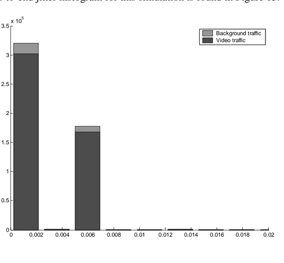
7. Simulation Results...41
7.1. BEST-EFFORT SIMULATION...41
7.2. ITERATION 1 ...44
7.3. ITERATION 2 ...46
7.4. CONCLUSIONS...48
8. Hardware Support for QoS ...49
8.1. CISCO...49
8.2. NORTEL NETWORKS...49
8.3. FOUNDRY NETWORKS...50
8.4. EXTREME NETWORKS...50
9. Conclusions and Future Work...51
9.1. CONCLUSIONS...51
9.2. FUTURE WORK...51
9.2.1. IPv6 ... 51
9.2.2. Aggregated RSVP ... 52
9.2.3. Integrated Services over Diffserv Networks ... 52
10. References ...53
A. The IP Header ...55
B. The Open Systems Interconnection Network Architecture...57
Table of Figures
Figure 1 - Routers and switches. ... 6
Figure 2 – Illustration of the functionality of a switch... 9
Figure 3 - The IP Type Of Service (TOS) field according to RFC 791... 11
Figure 4 - The IP Type of Service field according to RFC 1349... 11
Figure 5 - RED drop probability. [Davie et al.] ... 18
Figure 6 - A Diffserv domain ... 26
Figure 7 - Flow diagram for verifying QoS ... 31
Figure 8 - SmartBits testing of a device ... 34
Figure 9 - Test setup. ... 36
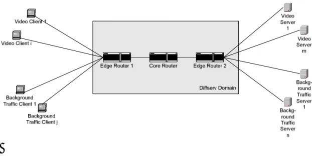
Figure 10 - Simulation scenario using ns-2. ... 38
Figure 11 - Queing and scheduling for the simulation scenario. ... 39
Figure 12 – End-to-end latency histogram for best-effort simulation. .... 42
Figure 13 – End-to-end jitter histogram for best-effort simulation. ... 43
Figure 14 - Latency histogram for iteration 1. ... 44
Figure 15 - Jitter histogram for iteration 1... 45
Figure 16 - Latency histogram for iteration 2 ... 46
Figure 17 - Jitter histogram for iteration 2... 47
Figure 18 - The Internet Protocol header... 55
Terminology
• AF – Assured Forwarding. A Diffserv PHB group that divides the PHB into a number of classes where each class has a number of drop precedence priorities. AF is defined in [RFC2597].
• Connection-based – A protocol that requires a connection to be set up before transmitting any data.
• Connection-less – A protocol that does not have a notion of a connection that needs to be set up at the beginning of a session and torn down at the end of the session.
• Datagram – The basic carrier of data in a connection-less network. A datagram contains data as well as address information.
• Diffserv – Differentiated Services. An architecture for implementing Quality of Service for aggregated network flows.
• DS Field – Differentiated Services Field. A field in the IP packet header that defines which service class a packet belongs to in the Diffserv architecture.
• DSCP – Differentiated Services CodePoint. Part of the IP header TOS field that is used to select the PHB a packet experiences at each node.
• EF – Expedited Forwarding. A Diffserv PHB defined in [RFC3246] used for building a low loss, low latency, low jitter, assured bandwidth and end-to-end service through Diffserv domains.
• ESDP – Ericsson Service Delivery Platform.
• Forwarding – The process of sending a packet to the next-hop node.
• Goodput – The rate at which packets are received at an endpoint.
• ICMP – Internet Control Message Protocol. A protocol that allows a router or destination host to communicate with the sender of an IP packet.
• IETF – The Internet Engineering Task Force. The organization responsible for creating and maintaining RFCs.
• IGMP – The Internet Group Management Protocol. A protocol that is used to support allocation and deallocation of temporary group IP addresses.
• IP – The Internet Protocol. The network protocol in use on the Internet.
• ISP – Internet Service Provider, the owner of a network that provides network services for customers.
• Jitter – Variation in latency between two consecutive packets.
• Latency – The time it takes a packet to reach its destination.
• ns-2 – A software package for simulating computer networks.
• PHB – Per-Hop Behavior. The externally observable behavior of a network node.
• Playback point – In multimedia applications, the playback point is the time offset between receiving a data sample and presenting it to the user
• RED – Random Early Detection. For more information, see section 3.4.3.
• RFC – Request For Comments. Internet reports that often contain specifications for network protocols.
• Routing – The process of building routing tables (tables of where to send packets destined for a specific IP address.
• RSVP – The Resource Reservation Protocol. Used by hosts to communicate their network requirements to intermittent network nodes.
• SLA – Service-Level Agreement. A contract between a customer and a service provider that specifies the forwarding service a customer should receive.
• Starvation – Occurs when a data flow is not able to deliver any
packets to the receiver, probably due to buffer overflow at some node.
• Throughput – The rate at which packets can be sent from a network node.
• Type of Service (TOS) Field – A field in the IP header that indicates which service level a packet should receive.
• UMTS – Universal Mobile Telecommunications System. An integral part in third generation mobile telecommunications.
• WFQ – Weighted Fair Queuing.
1.
Introduction
This chapter discusses the background to this master thesis and provides an overview of the contents.
1.1.
Background
Ericsson Center for Wireless Internet Integration manufactures a system called Ericsson Service Delivery Platform (ESDP). It is a bridge between computer services, such as e-mail, and networks for mobile units such as mobile phones. At the core of ESDP is an IP-Infrastructure (IP-Infra) that consists of network equipment such as switches, firewalls and proxies. New technology for mobile networks, such as UMTS, allows much faster transfer speeds than previously. This makes it feasible to deliver new services that were previously not possible. For example, it may be
possible to view full-motion video in real-time on mobile units. Demand for this new class of applications adds new requirements to the network, such as the ability to guarantee a certain bandwidth to a specific user in order to ensure that the user can watch the movie without interruptions. No such features are implemented in IP-Infra at present.
1.2.
Problem Description
Computer network traffic using the Internet Protocol is based on a “best effort” service model. This model states that each node in the network will make an attempt to deliver each packet of data to its destination within a reasonable time, but it makes no guarantees at all. Packets may be delivered late (where “late” is a relative term depending on the
application requirements) or not at all. Packets may also be reordered, that is, there is no guarantee that packets are received in the order they were sent. This service model is relatively simple to implement, and it is arguably one of the reasons why the Internet has been able to scale to the size it is today.
However, the best effort service model is inadequate if a service provider wants to guarantee a certain level of service for its customers. For
example, the service provider might want to guarantee that packets are delivered within a certain time or that a sustained bandwidth is delivered to the client. When using the current IP service model, it is not possible to make such guarantees.
IP-Infra serves as a platform for a multitude of services, and it is desirable to be able to implement a different service model than the currently
deployed best effort model. This master thesis will examine two QoS models that might be suitable to implement in IP-Infra and test these
models in the lab using a combination of software and hardware to determine how these models perform in IP-Infra. Pure software simulations will also be used.
1.3.
Limitations
The scope of this master thesis will be limited to concentrate on a few models/solutions for providing QoS and only one application, streaming video. Streaming video is an application that is very sensitive to the provided quality of service since dropped packets and jitter (variation in latency between consecutive packets, see section 3.3.2) will affect the quality of the video in a negative way.
Also, this report is limited to the problem of providing QoS in IP-Infra and not necessarily computer networks in general. However, since IP-Infra is an IP-based solution, most of this thesis will be applicable for most IP-based computer networks.
Since IPv4 is still the dominating version of the Internet Protocol in use today, this thesis is limited to IPv4.
A network simulation package called ns-2 has been used. Ns-2 is very resource-intensive and the simulations have therefore been scaled down in order to run at all. Also, some very simple modifications was made to the ns-2 source code (see section 6.2.3).
1.4.
Methodology
The work that has been done for this thesis can be divided into two parts, theoretical and practical. The theoretical part consists of reviewing how IP networks function and what parts of the basic best-effort service provided by the Internet Protocol that needs to be improved in order to implement an improved service quality. A number of QoS technologies was researched. During the theoretical work the architecture of IP-Infra was examined and a plan for implementing QoS in IP-Infra was
developed.
During the practical work some initial work was made to implement QoS in IP-Infra according to the plan that was developed during the theoretical phase. It became apparent that the plan would not work due to hardware
• Chapters 3-5 covers theory related to Quality of Service, available QoS models and how to implement and verify QoS in an IP
network.
• Chapters 6-7 describe the practical work that has been done for this thesis and the results of this work.
• Chapter 8 is a brief overview of hardware that is currently
available on the market and that is capable of implementing large-scale QoS.
• Chapter 9 contains the conclusions of this thesis and discusses what needs to be done in the future in order to implement QoS in IP-Infra and which technologies that may be worth examining further.
1.6.
Target Audience
This thesis is of interest to anyone who wants to know more about the theories behind quality of service in IP networks. It also covers practical information about how to implement and test QoS in a network.
For more detailed information about any topic covered here, please refer to the list of original material listed in the references.
2.
IP Networks
2.1.
Background
This chapter will describe computer networks using the Internet Protocol as their network protocol. The Internet Protocol (IP) is the most widely used protocol for computer networks today. The protocol is a relatively simple solution to the extremely complex problem of providing millions of hosts with network connectivity simultaneously. It was designed to be extremely scalable, which is proven by the fact that it is the protocol the Internet is built on. Robustness was also a key factor in the design of the Internet Protocol. Even if several nodes break down for some reason, the protocol is able to use another path and still deliver packets to the
destination.
2.2.
Packet Switching
Packet switching deals with the transmission of data in the form of packets (or datagrams). Traditionally, transmissions were connection-based, which means that a fixed amount of bandwidth is reserved for a transmission when it begins and deallocated when the transmission ends, making the bandwidth available for new connections. This means that in connection-based networks, a connection occupies bandwidth even when no data is sent. This is an inefficient use of the bandwidth, and packet switching was developed to use bandwidth more efficiently. The major advantage of a packet switched network is that data is only transmitted when there is available data to send. When there is no data to send, the bandwidth is available for the other users of the network. [Minoli et al., p.12]
Packet switching introduces problems that do not occur in connection-based networks. For example, the network runs a greater risk of becoming congested with data since computer network traffic usually occurs in bursts [Armitage, p. 28]. If several traffic bursts occur at the same time, the network becomes congested and will have to do something to remedy the situation. In packet switched networks, packets are simply dropped (i.e., forced off the network) when the load on a switch becomes too high and its buffers become full.
Packet switched networks are inherently connection-less, which means there is no dedicated physical link between sender and receiver. This means that even though two packets are delivered from the same source to the same destination, they might not take the same route to get there. In connection-based networks, a link is set up when the connection is
initiated and torn down when the connection is closed. The fact that packet switched networks are connection-less presents another problem: each node that each packet passes through must be able to determine which path to send the packet. Since network topology changes, there is no fixed path to send packets. The problem of finding a suitable path is very complex and does not always result in an optimal path (where the meaning of optimal depends on the application requirements). The process of finding this path is called routing.
2.2.1.
Routers, Switches and Bridges
Extended LAN LAN Ethernet Bridge LAN Ethernet Router Extended LAN LAN Ethernet Bridge LAN Ethernet Router Internet
also known as LAN switches, are layer 2 switches that are used to
implement an extended LAN (a collection of LANs connected by one or more bridges). Routers are layer 3 switches that move data between networks. [Perlman, p.493]
Routers perform two tasks: forwarding and routing. During routing, the router communicates with other routers to build routing tables that contain information about the routers it is connected to. These tables are used during forwarding to determine the next-hop for a packet to a certain destination. Routing is the most computationally expensive operation among the two. Forwarding simply looks up information in the routing tables.
A relatively new invention is switches that operate at the application layer (layer 7) of the OSI model (see appendix B). Layer 7 switches look at the context and the contents of the data being sent and forward packets based on this information. For example, a web switch (which would be an example of a layer 7 switch) has the ability to look at which webpage is being requested by a client and also information about which cookies the client holds (see below for a more detailed explanation). This information can then be used to forward packets belonging to that flow to the correct destination (see section 2.2 for more information about how packets are delivered). Typical features that layer 7 switches add to the “normal” switching functions are:
• Application grouping – Make sure that requests from a specific client are always handled by the same server. For example, during HTTP sessions it may be desirable to make sure that requests from the client are always handled by the same web server since all state information may not be synchronized between the servers. So even if a user is logged in to an account on one server, the other servers may not know about this even if they are supposed to handle the same web site. Application grouping solves this problem.
• URL switching – The ability to direct HTTP requests to the same group of servers based on the requested URL. For example, all HTTP requests which requests a page in the “/home” directory of a website are directed to a specific group of servers, while all
requests for pages in the “/cgi-bin” directory are handled by another group of servers.
• Cookie switching – This function is related to URL switching, but it directs requests to a specific group of servers based on
The features enumerated above all relate to a web application switch, which is the most common type of layer 7 switches today.
2.3.
The Internet Protocol
The Internet Protocol is the protocol used on the Internet and in most computer networks today. It is designed to impose as few requirements as possible on the underlying link technology, which is one of the key
factors to its success. It is used to implement a packet switched network, regardless of which type of network the lower layers of the network protocol hierarchy implements. [Davie, p.251]
Using IP, each node on the network receives a unique address, called the IP address. This address is used by all nodes that wish to communicate with the node. Because of the enormous growth of the Internet in recent years, the address space (the set of all available addresses) provided by the Internet Protocol is becoming depleted. Theoretically, the protocol can accomodate 232 hosts, but in reality the number of hosts that the addressing scheme can support is substantially smaller because of the complexities it would impose on routers to keep track of every single node’s address. Addresses are grouped together in order to keep this complexity within reasonable limits, but in the process addresses are wasted.
Problems such as the address space becoming depleted have caused the development of version 6 of IP (IPv6). The version of IP that dominates today is version 4 (IPv4). Besides dramatically increasing the number of available addresses (the IPv6 address space can theoretically accomodate 2128 hosts, but as in IPv4 the practical limit is smaller), IPv6 adds
improvements to IPv4 in areas of routing and autoconfiguration. IPv6 is already an accepted standard defined in [RFC2460], but it is not nearly as widespread as IPv4 which is still the dominating version of the Internet Protocol in use. [http://www.ipv6.org/]
2.3.1.
IP Packet Switching
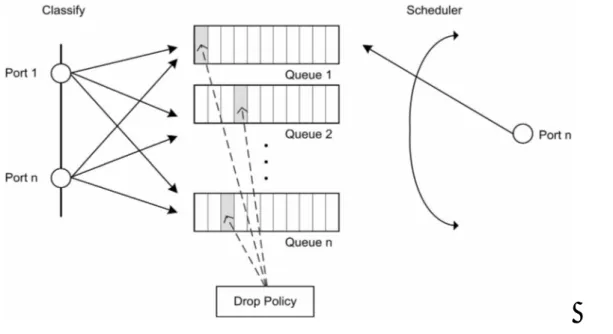
Figure 2 – Illustration of the functionality of a switch.
Figure 2 is a modification of an image found in [Armitage]. The original image is missing the “Drop Policy” box. The figure is discussed in the following paragraphs.
Packet switching (or packet forwarding) is the act of receiving a packet on a network interface and transmitting it to another network link. This is the central role of switches. Switching can occur at different levels in the OSI architecture, but the kind of switching we are interested in is IP packet switching. IP packet switching occurs at a router when a network node receives an IP packet, looks at its header and forwards the packet to the next hop network node, which may either be the destination of the packet or another router. Each node that the packet passes through must decide what to do with the packet.
When a packet is received by a router, it is either dropped or put in one of the router’s queues (many routers have only one queue). The drop policy determines which packets are dropped by the device (see section 3.4.3). Network traffic is generally bursty and bandwidth limited, and a router may not be able to cope with the network load during these bursts. The queue is a memory that acts as a buffer during these bursts. It allows the router to store the packet temporarily and send it as soon as possible. As soon as the router has sent a packet, it looks at its queues and selects the next packet to send (unless all queues are empty). Which packet to send next is decided by the router’s scheduler. The router then forwards the packet to the next hop according to the packet’s IP header and the router’s configuration. The scheduling algorithm is vital to QoS, since it makes it possible to expedite prioritized packets faster than normal
packets. See section 3.4.2 for more information about queuing disciplines and schedulers.
2.4.
The IP Service Model
The IP service model consists of two parts: an addressing scheme and a delivery model [Davie et al., p. 250]. The addressing scheme is not important for this work, but the delivery model is the part of IP that we wish to improve by implementing QoS.
The delivery model used in IP is called best effort because it makes no guarantees other than that it will try its best to deliver each packet to its destination. If critical conditions occur (such as a heavy load on the network) the packet may be delayed significantly or dropped altogether by any node on the network without notifying the sender. Dropped packets and packets delivered in another order than they were sent must be dealt with on a higher layer in the network architecture. Typically this is handled by the Transmission Control Protocol, TCP.
2.4.1.
Pros and Cons of the IP Service Model
One advantage of the IP service model is that it imposes very few
hardware requirements and allows a relatively simple implementation in the switches that forward IP traffic. Best effort service can be seen as the lowest common denominator of all network technologies, and therefore IP can be implemented on most network hardware. If the link technology provides a “better” service model than IP, such as guaranteed delivery of packets, IP automatically inherits those characteristics when running on top of that link technology, but still does not guarantee anything besides best effort service. [Davie, p.251]
For many applications, the best effort service model is adequate.
However, real-time applications and many multimedia applications can benefit from a guaranteed quality of service. For example, in order for a streaming video application to play video without loss of frames or degraded image quality, it is necessary for the application to know parameters such as packet delay and bandwidth or in some way reserve the bandwidth it requires.
2.4.2.
The IP Type of Service Field
Figure 3 - The IP Type Of Service (TOS) field according to RFC 791.
[RFC791] also defines a type of service (TOS) field in the IP header. The TOS field should serve as a marker for the type of service a client wants, and the network nodes should handle the packet differently according to the value of the TOS field. The specification defines four different service levels: precedence, delay, throughput and reliability (see Figure 3).
Routers can use the value of this field to choose a path for each packet based on different metrics – if a client wants short delays, a packet could take a specific route and if the client wishes high throughput another route could be chosen.
The precedence field determines how the packet should be treated as it traverses the network. The value (between 0 and 7) of these three bits determines the priority of the packet as it traverses intermediate network nodes. The Delay, Throughput and Reliability bits are set to minimize or maximize the indicated metric, with possible additional cost for the sender.
Figure 4 - The IP Type of Service field according to RFC 1349.
[RFC1349] redefines both the format and the semantics of the IP TOS field. Bits 3-7 now define the type of service, as opposed to three bits previously. The service levels defined by this document are: minimize delay, maximize throughput, maximize reliability, minimize monetary cost and normal service (the default TOS). These four bits are interpreted as integers rather than bit combinations as in RFC 791. The semantics of the TOS field as defined in [RFC1349] specifies a specific, limited model of traffic differentiation. The service marking model used in this RFC does not easily allow for customization and extension of the provided service level [RFC2475], although it does allow the addition of new values of the TOS field besides the four predefined values. Also, according to the specification, the packets are marked by the host that
sends the packet. This may not always be desirable, since nothing prevents clients from always choosing to label their packets with the highest priority.
The TOS field has not been widely deployed with neither its original semantics as defined in [RFC791] nor the definitions in [RFC1349]. With more recent terminology, the TOS field is often called the Diffserv field (see section 4.2).
3.
Quality of Service
This chapter discusses the theory behind Quality of Service in computer networks, as well as the possible benefits and problems associated with implementing QoS. It serves as a theoretical background for later
chapters.
3.1.
The Benefits of Implementing QoS
By implementing quality of service in a network, the service provider is able to give its customers certain guarantees regarding the service quality. The statements that can be made regarding the quality depend on which QoS model is implemented as well as inherent network parameters and network equipment.
Simply increasing the capacity of the network can solve many problems that are related to QoS. For example, in order to decrease the probability of packet loss, faster routers may be purchased and the bandwidth of the network increased. However, this solution only works up to a point (it’s impossible to buy arbitrarily fast routers and there are limits to the amount of bandwidth that may be purchased), and it is economically unfeasible. It is more economically sound to improve the service model of the existing network, possibly in combination with increasing the capacity, and then charge extra for users who want improved network performance. QoS focuses on using the network in a more efficient manner rather than increasing the resources.
3.2.
Network Components That Implement QoS
3.2.1.
Communication Protocols
As we have seen in section 2.4, the Internet Protocol does not implement any kind of QoS, which is the very problem that we are trying to solve. There are at least two ways to implement QoS using protocols – either let the protocol itself implement QoS or use a signaling protocol (which does not carry application data) in conjunction with an already existing
protocol such as IP. RSVP (see section 4.1.1) is an example of a signaling protocol that is used to implement QoS in conjunction with another
protocol, in this case IP.
If the communication protocol itself supports QoS, it is enough for applications to state their requirements and then the protocol will either deny access to the requested resources or reserve them for the
application’s use. That would be ideal from a QoS point of view, but QoS was not a priority when IP was developed. IP-Infra, as its name suggests,
needs to be based purely on IP which makes it impractical to use another protocol.
One example of a protocol that is capable of QoS is Asynchronous Transfer Mode (ATM), which is a link layer protocol (see appendix B).
3.2.2.
Routers and Switches
Since routers and switches are the devices that forward packets, they are also candidates for implementing QoS. They can do this using a non-standard technique, but this is usually accomplished by implementing a standard QoS scheme such as Integrated Services (see section 4.1) or Differentiated Services (see section 4.2). The rules defined by the standard determine the order in which the switch should send packets, which packets to discard and so on. In order for a router or switch to implement QoS, it must implement mechanisms for classifying, queuing and scheduling of packets (see section 3.4.1).
Any device capable of performing packet forwarding will be considered a switch in this thesis, so a firewall that performs switching functions will be regarded as a switch even though that is not the primary purpose of a firewall.
3.3.
Goals of Implementing Quality of Service
3.3.1.
Predictable Latency
Latency is the time that it takes for a packet to travel from its source to its destination. When implementing QoS, latency may be reduced by letting packets belonging to premium clients receive priority in the router’s buffers, so that as soon as a prioritized packet arrives at the router, it will be placed first in the router’s queue to be sent as soon as possible. This procedure forces packets with lower priority to have to wait longer in the router’s queue, thus receiving worse latency than they would if a best-effort service model was used. If there is a heavy load of premium
packets, the probability of dropping packets belonging to normal streams will increase, as the priority scheme will force the packets with lower priority to be dropped first.
applications are usually able to adjust their playback point to compensate for network latency.
3.3.2.
Predictable Jitter
Jitter is defined asJitter= Latency(Pn)−Latency(Pn−1) [Quynh et. al], where
Latency(Pi) is the latency of packet number i at the receiver. In other
words, jitter is the difference in latency between consecutive packets at the receiver.
For example, if a source sends packets with 30ms intervals and they are received at the destination with 30ms intervals, the jitter is 0. If the interval between two packets is something other than 30ms, the network has introduced jitter.
For many applications a high amount of jitter is worse than a high amount of latency because it introduces some degree of unpredictability into the data stream. As mentioned in the previous section, it is often possible to compensate for the delays caused by network latency, but latency by itself is constant. Jitter represents the variation in latency, which is not constant and usually not predictable.
3.3.3.
Predictable Packet Loss
Packet loss forces many applications and protocols to resend packets that have already been sent. This causes delays for the transmissions, since it takes time to notice that packets have been dropped and because it takes time to resend them (and make sure that the packet isn’t dropped once again). So packet loss is something that nobody wants but that is a reality due to limited buffers in network nodes. During transmission peaks, nodes are forced to drop packets if their buffers are full and new packets arrive.
One way to avoid packet loss would be to make sure that a network node has the capacity to send data faster than it receives data. However, that is usually not an option since it would be too expensive.
Packet loss can be dealt with in different ways by applications and/or network protocols. When using TCP, dropped packets are always resent by the protocol until it is acknowledged by the receiver that the packet was indeed received. Using this method, the same packet may traverse parts of the network several times. Another option is to use UDP instead of TCP and implement some other method of dealing with lost packets in the application. A third alternative is to simply ignore dropped packets, which may be feasible for some applications and protocols. For example,
a video conference application may prefer to play video with lower quality rather than resending packets in order to keep the delay low.
3.4.
QoS Mechanisms
3.4.1.
QoS Requirements
Implementation of QoS in a computer network can be divided into three distinct activities: classification, queuing and scheduling. In order to implement QoS, mechanisms to handle these activities must be present. [Armitage, p.41]
3.4.2.
Classification
Classification is performed when packets arrive at a router. It uses a set of rules to determine which class each packet belongs to. The classification of the packet then determines in which queue and where in that queue the packet should be inserted.
Classification must be based on a set of rules. There are a number of possible ways to classify packets and determine which queue they belong to. For example, if Differentiated Services is used (see section 4.2),
packets are classified according to the DS field of the IP header (see appendix A). Other possible ways to classify packets include looking at the destination IP address and/or port, source IP address or a combination.
3.4.3.
Queuing and Scheduling
As previously mentioned (in section 2.3.1), a queue is a buffer for packets. A router may have one or more queues. The scheduler
determines which packet to send from the available queues. Queuing and scheduling are sometimes dependent on each other, so they are treated side-by-side in this section.
Queuing can be divided into four basic activities according to [Armitage, p. 80]:
• Adding a packet to the correct queue. The queue to add the packet to is determined during the classification stage.
• FIFO – Packets are sent on a first-in first-out basis, that is, the first packet to arrive at the switch is the first packet to be sent. Packets are placed last in the queue when they arrive.
• Priority queuing - Packets are placed in different queues depending on their priority (how to select the priority of each packet is a policy decision). As long as a higher priority queue contains packets, these are sent. Queues with lower priorities won’t get served until all queues with higher priorities are empty. This increases the risk of starvation for lower-priority queues.
• Weighted Fair Queuing (WFQ) – This is a variation of priority queuing that decreases the risk of starvation of lower-priority packets. When using WFQ, each queue is given a weight. During a specified time interval known as the “time quantum”, the amount of data sent from each queue is proportional to its weight. This allows higher-priority data to receive better service while avoiding starvation for low priority data. The length of the time quantum is dependent on several parameters and it can be hard to determine an appropriate value. Starvation is something that should be avoided as far as possible because it may cause packets to be resent that shouldn’t have to be. Resending packets further increases the network load, since the same packets are sent several times.
The drop policy determines which packets to drop from the queue. It is vital to implementing a QoS scheme, as it makes it possible to discard specific packets from the network flow while leaving others. Discarding packets is necessary when the queue is full and new packets arrive, but some drop policies drop packets even when the queue is not full. The rationale for this is that when packets are dropped, the TCP algorithm will detect this and cut back on the rate with which it is sending packets. Some common drop policies are discussed in the following paragraphs.
Tail drop – When the buffers are full, packets are always dropped. If there is still room in the buffer, the packets is queued. The main strength of this drop policy is that it is very simple to implement and works well for best-effort networks.
Figure 5 - RED drop probability. [Davie et al.]
Random Early Detection (RED) – This drop policy discards packets randomly with a specified probability that is determined by the average queue size. No packets are dropped if the average queue occupancy is smaller than a specified number tmin, but when the average queue size is
between tmin and tmax, packets are dropped with a probability that is
linearly proportional to the queue length (see Figure 5). Of course, when the buffers are full packets are always dropped. RED helps prevent network congestion, but only when a transport protocol that is able to react to packet drops is used. TCP is an example of such a protocol, whereas UDP is not. One problem with RED is that it may cause packets to be received out of order at the receiver. Also, it may be difficult to determine the appropriate values for tmin and tmax.
Weighted Random Early Detection (WRED) – WRED is RED with the ability to use different drop probabilities and thresholds depending on which class of traffic a flow belongs to. WRED also prevents network
3.5.
Examples of Applications That Benefit From Quality of
Service
3.5.1.
Streaming Video
Streaming video applications benefit from a guaranteed minimum bandwidth as well as knowing the degree of jitter on the network. A minimum amount of bandwidth is always required to be able to play the video at a certain quality without interruptions. Knowing the jitter allows the client application to adjust its receiving buffer size so that it is able to play the video without interruptions even if some packets are delayed for a significant amount of time. The latency is not very important for
streaming video. Usually, users don’t care if the video clip they’re watching is delayed for a few hundred milliseconds after it is sent from the server. Streaming video benefits from implementing QoS in the network where these parameters can be guaranteed to be within specified limits. [Armitage, p. 108]
3.5.2.
Video Conferencing
Video conferencing imposes same constraints as streaming video with the addition of low latency requirements. During video conferencing, several participants communicate with each other using audio and video
simultaneously. However, humans are very sensitive to delays in speech (in general, for a conversation to occur between humans without
problems the delay needs to be less than 250 ms [Houser]), so latency is an issue during video conferencing. Most people find it frustrating to talk to someone if it takes seconds to get a response.
It is also important to be able to synchronize video and speech, so that people’s mouth movements are synchronized with the words they are saying. In order to synchronize video and speech it is important that the two streams are delivered simultaneously, so that both video and sound data have arrived when it is time to present them.
H.323 is a standard that solves many problems related to video
conferencing. It is a collection of components and protocols that can be used over packet based networks that do not provide a guaranteed Quality of Service, such as the Internet Protocol. H.323 is commonly used for voice over IP (VoIP) applications (support for audio is mandatory in H.323, data and video support is optional) and it solves many problems related to any kind of multimedia application such as specifying
3.6.
Business Advantages
Since QoS allows an operator to utilize the infrastructure of the network in a more controlled manner, it allows the Internet Service Provider (ISP) to differentiate between service levels. This, in turn, allows the ISP to provide different services to customers. A simple example of this would be an ISP that has two service levels: “normal” service level is the standard, best-effort service model of IP and “premium” service is a higher service level with guaranteed bandwidth, guaranteed latency etc. The agreement regarding network performance parameters is a part of the service level agreement (SLA) between the ISP and the customer.
The positive results for the ISP of this service differentiation are obvious:
• It makes it possible for the ISP to focus its resources on its most important customers.
• It gives the ISP a hint about the actual network needs of its customers, since those that require a lot of bandwidth are likely to subscribe to the premium service.
• The customers who are subscribing to the normal service are more likely to receive poor performance during hours when the network is under heavy load, but during times when the network is under light load the normal service customers will also receive acceptable performance. This makes those customers more inclined to use the network during those hours. This leads to more efficient usage of the network infrastructure, since the load is distributed more evenly during the day.
• It allows the ISP to deliver services to its customers that would
otherwise not be possible at all or would not get an acceptable level of quality. For example, the ISP could offer its customers streaming video on demand and guarantee that it has an acceptable quality. Of course, the ISP could also add several service levels with different service options. That would provide the same advantages as above but with different pricing schemes for different service levels.
How a customer is billed for network service is a very complex issue. The service provider wants to provide fair pricing for its customers, but will also want to minimize the cost for measuring the usage of the network for each client. Indeed, the largest cost of providing telephone service is the cost of measuring how many calls are made by whom each month.
There are several factors to take into consideration when deciding on how to bill your customers:
• The cost of measuring the factors that are the basis for billing clients.
• The factors that are the basis for billing should be understood by the customers. Telephone companies most often use either a flat-rate model of billing (where the customer pay a fixed sum each month) or a model based on how many minutes the phone has been used (or a combination of the two). Both of these approaches are easy to grasp for customers.
• In order to bill the correct customer, each customer must be identified in some way. This identification can be based on IP addresses of the client or some kind of logon/logoff scheme. The key characteristics of the identification should be that it is hard to forge someone’s identity as well as correctness of the identification method.
• Billing should be fair, so that customers get what they pay for.
Customers with premium service should be charged more. Otherwise, all customers would want the better service, which would either
increase the costs (since upgrading the network would be inevitable at some point in order to fill everyone’s needs) or decrease the level of the premium service.
• Determine if billing should be flat-rate or based on actual usage. The former is a simpler model to use but it may be unfair in the sense that some customers still use a disproportional amount of bandwidth. Billing based on actual usage is the most accurate model, but it may not always be the best model because of the costs associated with keeping track of how much data each customer uses.
For streaming video, there is also the possibility of charging per event (or movie) or per stream or a combination of the two. The combination would charge a fixed cost for making a movie available and then a fixed cost per user that accesses the video clip.
There are other possible billing models, but it is outside the scope of this report to go into detail about each possible model.
4.
Quality of Service Models
This chapter presents the two major architectures for IP QoS presented by the Internet Engineering Task Force (IETF). These two architectures have similar goals, but have focused on different aspects of implementing QoS. The first model is called Integrated Services. It uses a reservation-based model where each application will signal its requirements to all nodes along the network path to the destination node. When the requirements have been accepted by each node, the application begins the transmission of application data. The second architecture, Differentiated Services, uses packet marking (in other words, each packet is marked with a code in the IP header) to indicate which traffic class the packet belongs to. The intermittent network nodes handles network packets differently depending on which class they belong to and which relative priority within the class they have.
4.1.
Integrated Services
Integrated Services (Intserv), defined in [RFC1633], approaches quality of service by extending the best-effort service model to support real-time traffic requirements in addition to the current non-real-time requirements. The Intserv approach is an “Internet service model that includes best-effort service, real-time service and controlled link sharing” [RFC1633]. The service model has two kinds of real-time traffic: guaranteed and predictive.
Integrated Services requires routers to be able to reserve resources (such as a fixed amount of bandwidth) for different flows of network traffic. A flow would require state information about the flow to be kept at the router. That fundamentally changes the Internet model, which does not keep such information. However, the reservation of resources also makes it possible for Intserv to make “hard” claims about the service quality. Clients either get exactly what they ask for or their request for resources fails.
The Integrated Services approach is often criticized for not scaling well because of the state information that must be kept at the routers as well as the additional cost of processing that information [RFC2998, p.4]. Each router must keep information about each flow and use this state
information to determine how to handle packets within that flow. This is much more computationally expensive than just forwarding packets and limits the number of flows a router can handle.
4.1.1.
The Resource Reservation Protocol
The Resource Reservation Protocol (RSVP) is an Internet control protocol (like ICMP, IGMP or routing protocols) that is designed to
implement QoS in IP-based networks. The fact that it is a control protocol indicates that it is not intended to carry application data but rather used to send some form of control messages between network nodes. RSVP operates on top of IP in the network hierarchy and belongs to the transport protocol layer in the OSI model. [RFC2205, p.4] It works by sending messages in the background to nodes along a path. While RSVP is not strictly tied to Intserv, it is the most widely used setup protocol to communicate the needs of an application within Intserv. [RFC2998] When RSVP is used, each network node along the path from server to client must make sure that it is able to fulfill the requirements of the client. For example, the routers may reserve a certain amount of bandwidth for a stream or give packets belonging to that stream precedence over packets belonging to non-prioritized streams.
An implication of using RSVP with Intserv is the scalability issues that were discussed in section 4.1. While these issues are not strictly tied to RSVP, the Intserv architecture has these results. RSVP can theoretically be used to signal application requirements for classes of network traffic rather than individual flows. Also, the control messages sent by RSVP require additional bandwidth. When the number of clients reaches thousands or hundreds of thousands and each of those streams must be taken care of, these control messages may have a negative effect on the rest of the network.
Because the hardware requirements to implement RSVP in IP-Infra are currently not fulfilled (no hardware in IP-Infra supports RSVP) and because of apparent scalability problems, RSVP and Integrated services will not be examined further in this report.
4.2.
Differentiated Services
Differentiated Services (Diffserv) came about partially as a reaction to the overly complicated and resource-intensive Integrated Services approach. This approach is different from Intserv by aggregating flows into classes.
According to [Kilkki], the goals of Differentiated Services are:
• To solve the scalability problems of RSVP.
• To provide highly reliable IP service.
• To use several drop priority levels as the main tool.
• To provide low-delay service.
• To allow the implementation of any imaginable service through the core network mechanism.
The goals are achieved by constructing services as a combination of the following techniques according to [RFC2474]:
• Setting bits in an IP header field at network boundaries (autonomous system boundaries, internal administrative boundaries, or hosts),
• Using those bits to determine how packets are forwarded by the nodes inside the network, and
• Conditioning the marked packets at network boundaries in accordance with the requirements or rules of each service.
In other words, a network node marks packets, and the marking determines how nodes inside the network will handle the packet.
Conditioning of the network traffic is primarily done by using different drop policies for different classes. The externally observable behavior of a network node is called the per-hop behavior (PHB). PHBs “include the differential treatment an individual packet receives, as implemented by queue service disciplines and/or queue management disciplines”
[RFC2474]. The format of the Diffserv field (which replaces the IP TOS field) is described in [RFC2474].
The value of the DS field is called the Diffserv codepoint. A codepoint associates the packet with a desired per-hop behavior. The codepoints and PHBs are not standardized in the Diffserv specifications, but suggested PHBs and recommended codepoints are defined in [RFC2597] and [RFC3246]. [RFC2597] defines Assured Forwarding (AF) and
recommended codepoints for that PHB. Assured Forwarding is used to decrease the possibility of a network node dropping a packet. Expedited Forwarding (EF), defined in [RFC3246], is used to deliver data at a minimum transfer rate.
4.2.1.
Edge and Core Routers
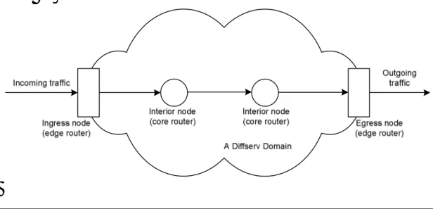
Figure 6 - A Diffserv domain
Diffserv makes a distinction between edge and core routers. An edge router deals with incoming or outgoing traffic to or from a Diffserv domain. The Diffserv domain may also contain one or more interior nodes, often called “core routers”. (see Figure 6). A boundary node that deals with incoming traffic is called an ingress node and a boundary node that deals with outgoing traffic is an egress node.
The ingress node usually acts as a traffic conditioner. According to [Diffserv, p.82], traffic conditioners perform the following functions:
• Marking packets by modifying their DS field.
• Shape the network traffic in order to smooth the traffic process of particular aggregate streams. (Smoothing means that bursts of data are queued at a node and sent with a more consistent bitrate.)
• Drop packets if necessary.
All these functions are performed in order to ensure that Service Level Agreements (SLAs) are fulfilled. For more information about SLAs, refer to section 4.2.2.
Packet dropping usually takes place in interior nodes, where the drop policy in combination with the packet marking determines the probability that the packet is dropped. In a Diffserv architecture, the interior nodes
using a Diffserv implementation are not as “hard” as those using Intserv. Diffserv is often called “soft” QoS. [Vegesna]
4.2.2.
Separating Policy and Implementation
Diffserv makes a clear distinction between policy and implementation. The policy building block in Diffserv is the definition of which service is to be provided, and is usually formally stated in a Service Level
Agreement (SLA), which is a contract between the service provider and the customer that defines, among other things, which service quality that should be delivered.
The implementation usually consists of a number of per-hop behaviors in order to make sure that the SLA is fulfilled. Each per-hop behavior is dependent on the capabilities and the configuration of the network node. Policy and implementation are dependant on each other. The
implementation of policies may be determined by which SLAs that the service provider wants to provide, but the available SLAs are also limited by the available implementation options. When formulating a SLA,
several factors must be taken into consideration:
• Under what conditions can the offered service level be delivered? Can the agreement be fulfilled even during peak hours, for example?
• How can this service level be continuously verified? (See section 5.3 for more information about this.)
• Does the service level agreement actually offer the customer something that they are willing to pay for?
According to [Kilkki], there are four primary approaches to define the services in a SLA:
• Guaranteed connections (dynamic bandwidth) – Using this model, the service provider sells network services based on individual
connections. Each connection receives variable bandwidth.
• Leased-line service (permanent bandwidth) – This model allows a customer to lease a fixed amount bandwidth for a fixed price. The bandwidth is reserved for the customer, and cannot be used by other customers even when it is unused. This approach does not require that a Diffserv scheme is implemented by the ISP but it does require that the hardware is able to statically reserve a fixed amount of bandwidth for a specific customer.
• Dynamic importance (dynamic precedence) – This model uses packet marking to reserve network resources and end-users buy a share of network resources permanently. The difference between this
model and leased-line service is that no “hard” reservations of network resources is made. This model allows the network owner to use
network resources in a more efficient manner, but the available
bandwidth for each individual customer may vary over time depending on the network load.
• Resource sharing (permanent share) – This model is similar to the previous one with the exception that it can also accommodate for applications that have special requirements such as low delay or high bandwidth. Using the previous model, there is no way for a customer to request special treatment and the point of the resource sharing model is to make it possible to do so.
Constructing SLAs is outside the scope of this thesis. For more information about how to design SLAs, please refer to [Kilkki].
5.
Verifying Quality of Service
The purpose of verifying QoS is to make sure that the network is behaving as expected, especially with regard to the QoS parameters specified in the SLA. Doing this in a production network is a tricky business and there does not seem to exist any standard benchmarks or methods for doing so. Most of the ideas in this chapter are the author’s own.
5.1.
Verification Models
There are three types of behaviors that are interesting: the end-to-end behavior, the per-hop behavior and the edge-to-edge behavior. This report will only briefly discuss edge-to-edge behavior since IP-Infra only
consists of one network and the edge-to-edge behavior and end-to-end behavior will be the same.
5.1.1.
End-to-End Behavior
The end-to-end performance of network traffic for the end-user is what we ultimately want to improve. The end-to-end behavior is the network behavior as measured from the sender (the server) to the receiver (the client).
We are interested in the following factors when verifying QoS for the end-to-end behavior of network transmissions:
• What is the end-to-end latency?
• What is the end-to-end jitter?
• What is the end-to-end throughput and goodput?
• What is the probability that a packet is dropped by the network and has to be resent?
• How many flows can the network handle at different data rates?
• How does priority-based network data affect normal data?
The end-to-end behavior is ultimately determined by the edge-to-edge behavior of each network that data passes through. The only way to improve the end-to-end behavior is by improving edge-to-edge behavior. The edge-to-edge behavior is, in turn, dependent on the per-hop behavior.
5.1.2.
Per-Hop Behavior
The externally observable behavior of each network node is called the per-hop behavior (PHB) [Armitage, p.36].
As the load on a network node increases, the node introduces larger delays to the network as the queue length increases at the node, provided that the node cannot send data as fast as it receives data. When data arrives fast enough at a node, the node is forced to drop packets because the queue buffer is limited by the available memory.
In order to verify the PHB of a network node, it is necessary to
characterize the network node in terms of latency, jitter and packet loss probabilities, both during normal and heavy load and for both prioritized and non-prioritized network traffic. [Armitage, p.36]
5.1.3.
Edge-to-Edge Behavior
The edge-to-edge behavior is the behavior of each network (or, in Diffserv terms, a Diffserv domain) that a packet traverses on its path to the destination. The edge-to-edge behavior can be characterized in the same terms as the PHB, and is largely dependent on the behavior of each node inside a network.
5.2.
Verification Strategy
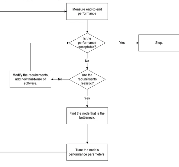
In order to ensure QoS, each node needs to be characterized in terms of latency, transfer rate, drop probability and jitter. The total performance can never be better than the weakest link, so the service quality needs to be improved at bottlenecks first. It is also important to remember that modifications to the behavior of one node may cause another node in a packet’s path to behave differently or become a new bottleneck. This fact calls for an iterative approach to verifying QoS (see Figure 7).
In order to verify QoS, the first thing to do is to determine the total end-to-end behavior of the network. If the end-end-to-end behavior is
unsatisfactory, it is necessary to find the weakest link in the network. This is done by measuring the per-hop performance for each node. When the per-hop performance is known, tune the bottleneck node’s configuration and perform the measurements again.
If a network is supposed to support several service level agreements, it is also important to measure the impact of the policy for one service level on the other service levels. For example, a policy that is supposed to
since it takes some time for the node to process each packet. This must be taken into account when deciding on a specific SLA.
When the end-to-end performance is acceptable, there is no need to further modify the network behavior. If this is the case, it is time to stop tuning the network nodes and instead continuously monitor the network so that it continues to behave as expected.
This process is illustrated in Figure 7.
Figure 7 - Flow diagram for verifying QoS
5.3.
Performance Monitoring
The purpose of performance monitoring is to ensure that customers continuously get the kind of service that they pay for. This requires continuous monitoring of the network in order to ensure that the requirements specified in the SLA are fulfilled by the provider.
There are no standardized methods for monitoring quality of service in computer networks. The measurements should be compared to the SLAs in order to ensure that the agreement is upheld. The measurements should
be made at the administrative endpoint of the network, where the SLA comes into effect. Analyzing log files produced inside the network is usually not very meaningful since nodes inside the network usually aren’t affected by the same factors as the network as a whole.
[RFC2330] specifies a general framework for performance monitoring. It discusses what characteristics the measurement and the metrics should have in order to be meaningful and relevant. The RFC introduces three distinct notions of metrics:
• Singleton metrics are atomic in some sense. For example, one
instance of a end-to-end delay measurement is a singleton metric, but also a end-to-end throughput measurement even if the latter would consist of measuring a number of IP packets.
• Sample metrics are a collection of related singleton metrics. In the case of measuring end-to-end delay, a sample metric would be one hour of measurements.
• Statistical metrics are derived from sample metrics by applying some statistical method to sample metrics. For example, the mean of end-to-end delays in the sample metric example above.
5.3.1.
Deciding What to Monitor
In order to ensure that customers actually receive the service quality that the SLA specifies, it is necessary for the service provider to continuously monitor the network and verify that the required metrics are within the limits specified by the SLA. In other words, the basis for performance monitoring should be the SLA.
The effects of the measurements on the network should be kept to a minimum. The less effect the actual monitoring has on the normal network flow, the more accurate the measurements are.
Typical metrics to use are latency, bandwidth and jitter.
5.3.2.
Methods of Collecting Samples
It is important to have a method for collecting the samples. One intuitive method is to collect samples periodically (with a fixed time delay
actually synchronize with them, affecting the precision of the samples. [RFC2330]
[RFC2330] suggests collecting samples using random additive sampling instead. This is a method where the time delay between each sample is independent and randomly generated with some statistical
distributionG(t). This makes it harder to manipulate the samplings and it also prevents the network from synchronizing with the measurements even if they affect the network. The RFC recommends that Poisson
sampling ( t
e t
G( )= 1− −λ ) is used.
The RFC also suggests using Geometric sampling if the situation allows it. When this method is used a number of events are monitored, but they are only recorded if a randomly generated number nis less than a given thresholdp. An example of an event could be the arrival of a packet at a specific node.
5.3.3.
Tools for Measuring Network Performance
There are a wide variety of software packages specifically aimed at monitoring the performance of networks. These packages fall into two categories: software-based (no extra hardware is required) and a
combination of software and designated hardware for performing performance testing.
Software-based tools are cheaper than those who require specific hardware to run but they may have scalability problems for very fast networks. Since they run on non-specialized hardware their performance may suffer. There are both free and commercial tools available. Some of the free tools that can be used for performance measurements are:
• Ping can be used to determine the round-trip time (RTT) of packets. In general, packet delay is half of the RTT.
• Pchar is a tool that gives more information than ping but is based on the same principles. Pchar returns information about each intermediate node between the source and the destination nodes. For each node, information about RTT as well as bandwidth and delay introduced by the node is presented. Ping only displays end-to-end RTT as result.
• Netperf is another free tool that consists of server and client software that must be installed to measure network performance. This is in contrast to ping and pchar, which relies on the operating system to respond to ping requests. This may make netperf more suitable for measuring network performance than the tools
mentioned above since it provides more control over the measurements.
The list above is in no way complete, there are many more software
packages available. It is outside the scope of this thesis to give a complete overview of this software.
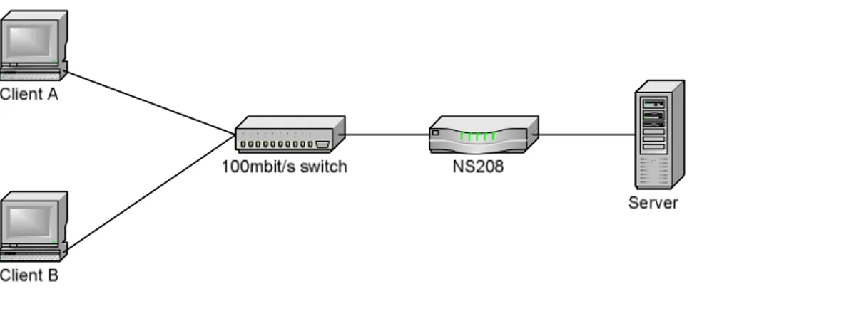
Figure 8 - SmartBits testing of a device
An example of a software/hardware-based solution is the SmartBits product line developed by Spirent Communications. SmartBits contains hardware that generates an enormous amount of packets and sends them through a network (see Figure 7). At the receiver another SmartBits device receives the packets and records information about the packet. When the test is done, the SmartBits software (running on Microsoft Windows) analyzes the packet data and presents the results. The main advantage over purely software-based systems is that the SmartBits packet generators manages to put a very high load on the device under test (the DUT) and the generated traffic is easily customized using the SmartBits software. The software also generates meaningful information based on the available data and assists the user in finding problem areas of the network.
5.3.4.
Deriving Meaningful Results from Measurements
In order to use the measurements, they need to be collected and analyzed. How they are collected was discussed in the previous section. Analyzing the results is usually done using mathematical tools such as statistical analysis.
An example of how to perform statistical analysis on measurement data can be found in chapter 7. Here, the primary mathematical tool for

![Figure 5 - RED drop probability. [Davie et al.]](https://thumb-eu.123doks.com/thumbv2/5dokorg/5390536.137599/28.892.142.760.113.571/figure-red-drop-probability-davie-et-al.webp)