J-PARC Neutrino Beamline Upgrade Technical Design Report
T2K Collaboration and J-PARC Neutrino Facility group
August 15, 2019
Abstract
In this document, technical details of the upgrade plan of the J-PARC neutrino beamline for the extension of the T2K experiment are described [1]. T2K has proposed to accumulate data corresponding to 2 × 10²² protons-on-target in the next decade, aiming at an initial
observation of CP violation with 3σ or higher significance in the case of maximal CP viola-tion. Methods to increase the neutrino beam intensity, which are necessary to achieve the proposed data increase, are described.
The T2K Collaboration
K. Abe52, H. Aihara51,26, A. Ajmi29, C. Alt9, C. Andreopoulos50,31, M. Antonova24, S. Aoki28,
Y. Asada65, Y. Ashida29, A. Atherton50, E. Atkin18, S. Ban29, F.C.T. Barbato21, M. Barbi43,
G.J. Barker61, G. Barr39, M. Batkiewicz13, A. Beloshapkin24, V. Berardi20, L. Berns54, S. Bhadra66,
J. Bian3, S. Bienstock40, A. Blondel11, S. Bolognesi4, J. Borg18, B. Bourguille 15, S.B. Boyd61, D. Brailsford30, A. Bravar11, S. Bron11, C. Bronner52, M. Buizza Avanzini8, N.F. Calabria20,
J. Calcutt33, R.G. Calland26, D. Calvet4, T. Campbell6, S. Cao14, S.L. Cartwright48, M.G. Catanesi20, A. Cervera16, A. Chappell61, D. Cherdack6, N. Chikuma51, G. Christodoulou10, M. Cicerchia19, A. Clifton6, G. Cogo22, J. Coleman31, G. Collazuol22, D. Coplowe39, A. Cudd33, A. Dabrowska13, A. Delbart4, A. De Roeck10, G. De Rosa21, T. Dealtry30, A. Dell’acqua10, P.F. Denner61,
S.R. Dennis31, C. Densham50, D. Dewhurst39, F. Di Lodovico42, S. Dolan39, N. Dokania36,
D. Doqua11, O. Drapier8, K.E. Duffy39, J. Dumarchez40, P.J. Dunne18, M. Dziewiecki60,
L. Eklund12, S. Emery-Schrenk4, S. Fedotov24, P. Fernandez47, T. Feusels2, A.J. Finch30,
G.A. Fiorentini66, G. Fiorillo21, M. Fitton50, M. Friend14,a, Y. Fujii14,a, R. Fujita51, D. Fukuda37,
R. Fukuda56, Y. Fukuda34, K. Fusshoeller9, A. Gendotti9, C. Giganti40, F. Gizzarelli4, M. Gonin8,
A. Gorin24, F. Gramegna19, M. Guigue40, D.R. Hadley61, J.T. Haigh61, S.-P. Hallsj¨o12, P.
Hamacher-Baumann46, D. Hansen41, J. Harada38, M. Hartz26,58, T. Hasegawa14,a, N.C. Hastings43,
Y. Hayato52,26, A. Hiramoto29, M. Hogan6, J. Holeczek49, F. Iacob22, A.K. Ichikawa29, M. Ikeda52,
J. Imber8, T. Ishida14,a, T. Ishii14,a, T. Ishii51, M. Ishitsuka56, E. Iwai14, K. Iwamoto51,
A. Izmaylov16,24, B. Jamieson63, M. Jiang29, S. Johnson5, P. Jonsson18, C.K. Jung36,b, M. Kabirnezhad35, A.C. Kaboth45,50, T. Kajita53,b, H. Kakuno55, J. Kameda52, S. Kasetti32, Y. Kataoka52,
T. Katori42, E. Kearns1,26,b, M. Khabibullin24, A. Khotjantsev24, T. Kikawa29, H. Kim38, S. King42, J. Kisiel49, A. Knight61, A. Knox30, T. Kobayashi14,a, L. Koch50, A. Konaka58, L.L. Kormos30, A. Korzenev11, Y. Koshio37,b, K. Kowalik35, W. Kropp3, Y. Kudenko24,c, S. Kuribayashi29, R. Kurjata60, T. Kutter32, M. Kuze54, L. Labarga47, J. Lagoda35, I. Lamont30,
M. Lamoureux4,22, D. Last36, M. Laveder22, M. Lawe30, T. Lindner58, Z.J. Liptak5, R.P. Litchfield12,
S. Liu36, K.R. Long18, A. Longhin22, J.P. Lopez5, L. Ludovici23, X. Lu39, T. Lux15, L. Magaletti20,
L. Magro52, K. Mahn33, M. Malek48, S. Manly44, T. Marchi19, L. Maret11, A.D. Marino5,
J.F. Martin57, S. Martynenko36, T. Maruyama14,a, T. Matsubara14, K. Matsushita51, V. Matveev24,
C. Mauger36, K. Mavrokoridis31, E. Mazzucato4, M. McCarthy66, N. McCauley31, K.S. McFarland44,
C. McGrew36, A. Mefodiev24, C. Metelko31, M. Mezzetto22, P. Mijakowski35, J. Mijakowski13,
A. Minamino65, O. Mineev24, S. Mine3, A. Missert5, M. Miura52,b, L. Molina Bueno9, S. Moriyama52,b,
J. Morrison33, Th.A. Mueller8, S. Murphy9, Y. Nagai5, T. Nakadaira14,a, M. Nakahata52,26,
Y. Nakajima52, A. Nakamura37, K.G. Nakamura29, K. Nakamura26,14,a, S. Nakayama52,26,
T. Nakaya29,26, K. Nakayoshi14,a, C. Nantais57, T.V. Ngoc17, K. Nishikawa14,a, Y. Nishimura27, T. Nonnenmacher18, F. Nova50, P. Novella16, J. Nowak30, J.C. Nugent12, H.M. O’Keeffe30, T. Odagawa29, R. Ohta14,a, K. Okamoto65, K. Okumura53,26, T. Okusawa38, T. Ovsyannikova24, R.A. Owen42, Y. Oyama14,a, V. Palladino21, V. Paolone41, M. Pari22, W. Parker45, S. Parsa11, J. Pasternak18, C. Pastore20, M. Pavin58, D. Payne31, J.D. Perkin48, L. Pickard48, L. Pickering33, E.S. Pinzon Guerra66, B. Popov40,d, M. Posiadala-Zezula59, J.-M. Poutissou58, R. Poutissou58,
J. Pozimski18, P. Przewlocki35, H. Przybilsk13, B. Quilain14, T. Radermacher46, E. Radicioni20,
B. Radics9, P.N. Ratoff30, E. Reinherz-Aronis6, C. Riccio21, P. Rojas6, E. Rondio35, B. Rossi21,
S. Roth46, A. Rubbia9, A.C. Ruggeri21, C.A. Ruggles12, A. Rychter60, K. Sakashita14,a, F. S´anchez11,
C.M. Schloesser9, K. Scholberg7,b, J. Schwehr6, M. Scott18, Y. Seiya38, T. Sekiguchi14,a, H. Sekiya52,26,b,
D. Sgalaberna10, A. Shaikina24, R. Shah50,39, A. Shaikhiev24, F. Shaker63, D. Shaw30, M. Shiozawa52,26,
T. Shirahige37, W. Shorrock18, A. Smirnov24, M. Smy3, J.T. Sobczyk64, H. Sobel3,26, F.J.P. Soler12,
L. Southwell30, R. Spina20, J. Steinmann46, T. Stewart50, P. Stowell48, S. Suvorov24, A. Suzuki28,
S.Y. Suzuki14,a, Y. Suzuki26, J. Swierblewski13, M. Szeptycka35, S. Szoldos42, A. Sztuc18,
R. Tacik43,58, M. Tada14,a, M. Tajima29, A. Takeda52, Y. Takeuchi28,26, H.K. Tanaka52,b,
H.A. Tanaka57,58,e, L.F. Thompson48, W. Toki6, T. Tomura52, C. Touramanis31, K. Tsui31, T. Tsukamoto14,a, M. Tzanov32, M.A. Uchida18, Y. Uchida18, M. Vagins26,3, N.H. Van17,25, G. Vasseur4, T. Viant9, C. Vilela36, T. Wachala13, C.W. Walter7,b, Y. Wang36, D. Wark50,39, M.O. Wascko18, A. Weber50,39, R. Wendell29,b, R.J. Wilkes62, M.J. Wilking36, J.R. Wilson42, R.J. Wilson6, K. Wood36, C. Wret44, Y. Yamada14,a, K. Yamamoto38, C. Yanagisawa36,f, G. Yang36, T. Yano52, K. Yasutome29, S. Yen58, N. Yershov24, M. Yokoyama51,b, T. Yoshida54,
T. Yuan5, M. Yu66, A. Zalewska13, J. Zalipska35, L. Zambelli14,a, K. Zaremba60, M. Ziembicki60,
E.D. Zimmerman5, M. Zito4,
The J-PARC Neutrino Facility group
E. Hamada11,a, N. Higashi11,a, E. Hirose11,a, Y. Igarashi11,a, M. Iida11,a, M. Iio11,a, M. Ikeno11, N. Kimura11,a, N. Kurosawa11,a, Y. Makida11,a, T. Nakamoto11,a, T. Ogitsu11,a, H. Ohhata11,a, R. Okada11,a, T. Okamura11,a, M. Onaka11,a, K. Sasaki11,a, S. Shimazaki11,a, M. Shoji11,a, M. Sugano11,a, K. Tanaka11,a, M. Tanaka11,a, A. Terashima11,a, T. Tomaru11,a, T. Uchida11,a,
M. Yoshida11,a
1 Boston University, Department of Physics, Boston, Massachusetts, U.S.A.
2University of British Columbia, Department of Physics and Astronomy, Vancouver, British
Columbia, Canada
3University of California, Irvine, Department of Physics and Astronomy, Irvine, California,
U.S.A.
4 IRFU, CEA Saclay, Gif-sur-Yvette, France
5 University of Colorado at Boulder, Department of Physics, Boulder, Colorado, U.S.A. 6 Colorado State University, Department of Physics, Fort Collins, Colorado, U.S.A. 7 Duke University, Department of Physics, Durham, North Carolina, U.S.A.
8 Ecole Polytechnique, IN2P3-CNRS, Laboratoire Leprince-Ringuet, Palaiseau, France 9 ETH Zurich, Institute for Particle Physics, Zurich, Switzerland
10 CERN European Organization for Nuclear Research, CH-1211 Geneva 23, Switzerland 11 University of Geneva, Section de Physique, DPNC, Geneva, Switzerland
12 University of Glasgow, School of Physics and Astronomy, Glasgow, United Kingdom 13 H. Niewodniczanski Institute of Nuclear Physics PAN, Cracow, Poland
14 High Energy Accelerator Research Organization (KEK), Tsukuba, Ibaraki, Japan 15Institut de Fisica d’Altes Energies (IFAE), The Barcelona Institute of Science and
Tech-nology, Campus UAB, Bellaterra (Barcelona) Spain
16 IFIC (CSIC & University of Valencia), Valencia, Spain
17Institute For Interdisciplinary Research in Science and Education (IFIRSE), ICISE, Quy
Nhon, Vietnam
18 Imperial College London, Department of Physics, London, United Kingdom 19 INFN Laboratori Nazionali di Legnaro LNL, Padova, Italy
20 INFN Sezione di Bari and Universit`a e Politecnico di Bari, Dipartimento
Interuniversi-tario di Fisica, Bari, Italy
21 INFN Sezione di Napoli and Universit`a di Napoli, Dipartimento di Fisica, Napoli, Italy 22INFN Sezione di Padova and Universit`a di Padova, Dipartimento di Fisica, Padova, Italy 23 INFN Sezione di Roma and Universit`a di Roma “La Sapienza”, Roma, Italy
24 Institute for Nuclear Research of the Russian Academy of Sciences, Moscow, Russia 25Institute of Physics (IOP), Vietnam Academy of Science and Technology (VAST), Hanoi,
Vietnam
26 Kavli Institute for the Physics and Mathematics of the Universe (WPI), The University
of Tokyo Institutes for Advanced Study, University of Tokyo, Kashiwa, Chiba, Japan
27 Keio University, Department of Physics, Kanagawa, Japan 28 Kobe University, Kobe, Japan
29 Kyoto University, Department of Physics, Kyoto, Japan
30 Lancaster University, Physics Department, Lancaster, United Kingdom 31 University of Liverpool, Department of Physics, Liverpool, United Kingdom
32Louisiana State University, Department of Physics and Astronomy, Baton Rouge, Louisiana,
U.S.A.
33 Michigan State University, Department of Physics and Astronomy, East Lansing,
Michi-gan, U.S.A.
35 National Centre for Nuclear Research, Warsaw, Poland
36 State University of New York at Stony Brook, Department of Physics and Astronomy,
Stony Brook, New York, U.S.A.
37 Okayama University, Department of Physics, Okayama, Japan 38 Osaka City University, Department of Physics, Osaka, Japan 39 Oxford University, Department of Physics, Oxford, United Kingdom
40 UPMC, Universit´e Paris Diderot, CNRS/IN2P3, Laboratoire de Physique Nucl´eaire et
de Hautes Energies (LPNHE), Paris, France
41University of Pittsburgh, Department of Physics and Astronomy, Pittsburgh,
Pennsylva-nia, U.S.A.
42 Queen Mary University of London, School of Physics and Astronomy, London, United
Kingdom
43 University of Regina, Department of Physics, Regina, Saskatchewan, Canada
44 University of Rochester, Department of Physics and Astronomy, Rochester, New York,
U.S.A.
45 Royal Holloway University of London, Department of Physics, Egham, Surrey, United
Kingdom
46 RWTH Aachen University, III. Physikalisches Institut, Aachen, Germany
47 University Autonoma Madrid, Department of Theoretical Physics, Madrid, Spain 48University of Sheffield, Department of Physics and Astronomy, Sheffield, United Kingdom 49 University of Silesia, Institute of Physics, Katowice, Poland
50 STFC, Rutherford Appleton Laboratory, Harwell Oxford, and Daresbury Laboratory,
Warrington, United Kingdom
51 University of Tokyo, Department of Physics, Tokyo, Japan
52University of Tokyo, Institute for Cosmic Ray Research, Kamioka Observatory, Kamioka,
Japan
53 University of Tokyo, Institute for Cosmic Ray Research, Research Center for Cosmic
Neutrinos, Kashiwa, Japan
54 Tokyo Institute of Technology, Department of Physics, Tokyo, Japan 55 Tokyo Metropolitan University, Department of Physics, Tokyo, Japan 56 Tokyo University of Science, Department of Physics, Tokyo, Japan 57 University of Toronto, Department of Physics, Toronto, Ontario, Canada 58 TRIUMF, Vancouver, British Columbia, Canada
59 University of Warsaw, Faculty of Physics, Warsaw, Poland
60 Warsaw University of Technology, Institute of Radioelectronics, Warsaw, Poland 61 University of Warwick, Department of Physics, Coventry, United Kingdom 62 University of Washington, Department of Physics, Seattle, Washington, U.S.A. 63 University of Winnipeg, Department of Physics, Winnipeg, Manitoba, Canada 64 Wroclaw University, Faculty of Physics and Astronomy, Wroclaw, Poland 65 Yokohama National University, Faculty of Engineering, Yokohama, Japan
66 York University, Department of Physics and Astronomy, Toronto, Ontario, Canada a also at J-PARC, Tokai, Japan
b affiliated member at Kavli IPMU (WPI), the University of Tokyo, Japan
c also at National Research Nuclear University ”MEPhI” and Moscow Institute of Physics
and Technology, Moscow, Russia
d also at JINR, Dubna, Russia
ealso at Institute of Particle Physics, Canada
Contents
1 Introduction 8
1.1 Overview . . . 8
1.2 The requirement for the neutrino beam for extended running of T2K . . . 8
1.3 The upgrade plan of J-PARC accelerator and the prospects of proton beam intensity of J-PARC MR . . . 10
1.4 Beamline upgrade toward >1.3 MW operation . . . 11
2 Primary Beamline and Beam Monitors 13 2.1 Introduction . . . 13 2.2 Primary beamline . . . 14 2.2.1 Optics . . . 14 2.2.2 Beam loss . . . 15 2.2.3 Normal-conducting magnets . . . 16 2.2.4 Super-conducting magnets . . . 16 2.2.5 Vacuum system . . . 17 2.2.6 Collimator . . . 17 2.2.7 Beam Plug . . . 18
2.3 Upgrade plan of the primary beamline . . . 19
2.3.1 Beam optics and larger aperture magnets . . . 19
2.3.2 Collimator . . . 20
2.3.3 Beam plug . . . 21
2.4 Proton beam monitors . . . 21
2.4.1 Segmented Secondary Emission Monitor (SSEM) . . . 22
2.4.2 Wire Secondary Emission Monitor (WSEM) . . . 24
2.4.3 Optical Transition Radiation Monitor (OTR) . . . 27
2.4.4 Proton Beam Monitor Upgrade Summary . . . 30
2.5 Maintenance senario of the primary beamline . . . 30
2.5.1 Normal-conducting magnets . . . 31
2.5.2 Vacuum flange operation . . . 32
2.5.3 Maintenance scheme of the most-downstream part of the final focus section . . . 32
2.5.4 Summary . . . 34
2.6 Muon monitor (MUMON) . . . 34
2.6.1 Muon Monitor Upgrades . . . 37
3 Secondary Beamline 39 3.1 Introduction . . . 39
3.1.1 Overview . . . 39
3.1.2 Operation status . . . 44
3.1.3 Current acceptable beam power and upgrade plan . . . 46
3.2 Target . . . 47
3.2.1 Target Design Overview and Current Operation Status . . . 47
3.2.2 Target helium pipes and isolators . . . 49
3.2.3 Target Design changes . . . 51
3.2.4 Upgrade to 1.3 MW . . . 51
3.3 Beam window . . . 54
3.3.1 Window Design Overview . . . 55
3.3.2 Stress and Cooling Analyses for 1.3 MW Operation . . . 55
3.3.3 Operation / Spare Production Status . . . 58
3.3.4 Upgrade for 1.3 MW Operation . . . 60
3.4 Horn . . . 61
3.4.1 Overview . . . 61
3.4.2 Operation status . . . 68
3.4.4 Upgrade plan . . . 74
3.4.5 Schedule . . . 84
3.5 Remote maintenance of secondary beamline equipment . . . 85
3.5.1 Overview . . . 85
3.5.2 Target . . . 87
3.5.3 Beam window . . . 89
3.5.4 Horn . . . 92
3.5.5 Beam monitors . . . 96
3.5.6 Disposal scenario of the irradiated equipment . . . 96
3.6 Cooling capacity upgrade . . . 97
3.7 Radiation shielding . . . 104
3.8 Disposal of radioactive water . . . 106
3.8.1 Overview . . . 106
3.8.2 Operation status . . . 107
3.8.3 Prospect and issues for the operation beyond 750kW beam power . . . 108
3.8.4 Upgrade plan and schedule . . . 109
3.9 Secondary beamline alignment . . . 109
4 Beamline DAQ and control 112 4.1 Introduction . . . 112
4.2 Beamline DAQ upgrade . . . 112
4.3 GPS upgrade plan . . . 114
4.4 Beam interlock improvement . . . 115
4.5 Radiation effects on the electronics . . . 117
5 Neutrino Flux Prediction 118 6 Summary 119 A Possible further neutrino beam-line upgrade 120 A.1 Beam Induced Fluorescence Monitor (BIF) . . . 120
Executive summary
T2K, Tokai to Kamioka long-baseline neutrino oscillation experiment, is an accelerator-based neutrino experiment using high intense muon neutrino beam from J-PARC accelerator and Super-Kamiokande as a far detector, located 295 km away from J-PARC. T2K revealed the existence of νµ → νe oscillation phenomenon in 2013 [2]. After the discovery, CP
violation in neutrino sector has been explored, increasing the statistics o both νµ→ νeand
¯
νµ→ ¯νeoscillations. In 2017, T2K reported the results of 2σ significance to exclude the CP
conservation with data up to 2.2×10²¹protons on target. T2K has proposed to extend the
run from 7.8×10²¹POT to 20×1021POT to improve the sensitivity of neutrino CP violation
with significantly improved statistics. To increase the statistics, J-PARC accelerator and T2K neutrino beamline groups proposed beam power improvement toward 1.3 MW and neutrino beamline upgrades to be achieved by 2026. In this document, technical details of the neutrino beamline upgrades are described.
1
Introduction
1.1
Overview
The Tokai to Kamioka Long Baseline Neutrino Oscillation Experiment (T2K) uses the νµ
(muon neutrino) beam produced by the J-PARC neutrino beamline to measure νµ to νe
(electron neutrino) and νµ to νµ neutrino oscillations after the neutrinos propagate 295 km
to the Super-Kamiokande far detector. Since the neutrino cross section is small, the neutrino flux should be as large as possible to maximize the number of interactions in the far detector. Various upgrades to the J-PARC accelerator are under way in order to increase the J-PARC neutrino flux for T2K and subsequent experiments, as discussed in this document.
The J-PARC complex is shown in Fig. 1. The neutrino beam for the T2K experiment is produced using 30 GeV protons from the J-PARC Main Ring accelerator (MR). Protons extracted from the MR are bent towards the Super-Kamiokande direction and focused onto the neutrino production target in the neutrino primary beamline, which is described in Sec. 2. Neutrino parent hadrons outgoing from the target are focused and allowed to decay, producing a neutrino beam, in the neutrino secondary beamline, which is described in Sec. 3.
Figure 1:
The J-PARC accelerator complex.1.2
The requirement for the neutrino beam for extended running
of T2K
After the discovery of νµ→ νeoscillation by T2K, neutrino CP violation is being explored
increasing the statistics of both νµ→ νeand ¯νµ→ ¯νeoscillations. In 2017, T2K has shown
the results of 2σ significance to exclude the CP conservation with data up to 22.3 × 10²⁰
protons on the target (POT), which is 30% of the original T2K target POT. The next generation projects such as Hyper-Kamiokande [3] and DUNE [4] aim to achieve greater than 3σ sensitivity to CPV across a wide range of δCP on the time scale of 2026 and
beyond.
The T2K collaboration proposes to extend the run from 7.8 × 10²¹ POT to 20 × 1021
POT in a five or six year period after the currently approved running to explore CP violation with sensitivity greater than 3σ if δCP ∼ −π2 and the mass hierarchy is normal. We can also
improve a precision of neutrino oscillation parameters, θ23 and ∆m232, to 1.7◦ or better and
1%, respectively, with the proposed POT. We refer to this extended running as “T2K-II” [1]. In this proposal, T2K requires the increase of the MR beam power up to 1.3 MW. After the T2K-II proposal was submitted, the schedule of the MR beam power improvement was
revised based on the funding situation and then the installation of the MR main power supply, which is one of major upgrade items described in Sec. 1.3, will be performed in 2021 instead of 2019[5, 6]. Figure 2 shows our target data accumulation scenario where six months of the MR operation with the fast-extraction mode each year and the running time efficiency of 90% are assumed. In this plot, it is also assumed that the MR beam power upgrade is performed earlier than the schedule shown in IAC2018[5] based on the discussion with the MR group, where it is considered that half a year ahead schedule of the MR main power supply and one year ahead schedule of the MR RF upgrade assuming allocation of the supplemental budget. The CPV sensitivity greater than 3σ is expected to achieve around 2026 in the case of δCP = −π2 and the sin2θ23 = 0.5 where these values are close to the
T2K 2018 summer results[7]. The 20 × 1021 POT required in the T2K-II proposal is also
expected to achieve by the end of the Japanese fiscal year of 2027.
Figure 2:
Our target MR beam power and accumulated POT as a function of Japanese Fiscal Year (JFY). The solid lines are the our target MR beam power (red) and accumulated POT (blue) where six months of the MR operation with the fast-extraction mode each year and the running time efficiency of 90% are assumed. It is also assumed that the MR beam power upgrade is performed earlier than the schedule shown in IAC2018[5] as described in the text. In this case, the MR main power supply installation is assumed to be performed from July 2020 to September 2021. The dashed lines are the target MR beam power (red) and accumulated POT (blue) shown in T2K-II proposal[1] where the MR main power supply installation was scheduled in 2019.Moreover, further improvements are planned to increase the effective statistics and the sensitivity. Increasing the electromagnetic horn current from the present 250 kA to the designed 320 kA will result in 10% greater neutrino flux while reducing the wrong sign components. Improvement of neutrino flux prediction uncertainty can make benefits on better understanding of the neutrino interaction models and neutrino oscillation analysis.
In the following sections, the detailed plan how to realize those requirements on the neutrino beam for T2K-II will be discussed. Those requirements are also common for the future projects, Hyper-Kamiokande, since the same beamline is utilized.
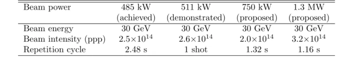
Table 1:
Summary of the MR operation parameters for the current and proposed beam power.Beam power 485 kW 511 kW 750 kW 1.3 MW
(achieved) (demonstrated) (proposed) (proposed)
Beam energy 30 GeV 30 GeV 30 GeV 30 GeV
Beam intensity (ppp) 2.5×10¹⁴ 2.6×10¹⁴ 2.0×10¹⁴ 3.2×10¹⁴
Repetition cycle 2.48 s 1 shot 1.32 s 1.16 s
1.3
The upgrade plan of J-PARC accelerator and the prospects of
proton beam intensity of J-PARC MR
The J-PARC accelerator consists of a normal-conducting LINAC as an injection system, a Rapid Cycling Synchrotron (RCS), and a Main Ring synchrotron (MR). H− ion beams are accelerated to 400 MeV by the LINAC and then injected to the RCS ring, where conversion into a proton beam is achieved by charge-stripping foils. The RCS accumulates and acceler-ates two proton beam bunches up to 3 GeV at a repetition rate of 25 Hz. Four beam pulses are injected from the RCS to the MR at 40 ms intervals to form eight bunches in a cycle, and accelerated up to 30 GeV. The circulating proton beam bunches are extracted within a single turn into the neutrino primary beamline by a kicker/septum magnet system in fast extraction (FX) mode operation.
The MR beam power has been increased gradually since the start of the user operation in 2010. The 485 kW proton beam with 2.5×10¹⁴ protons per pulse (ppp) at 2.48 s cycle
was successfully provided to the neutrino beamline as of April 2018. The current plan to achieve the design beam power of 750 kW is to reduce the repetition cycle to 1.3 s. With the currently achieved beam intensity, the MR beam power can be increased to 900 kW at 1.3 s cycle. In a high intensity trial, a single-shot beam with 2.6×10¹⁴ ppp was successfully extracted to the neutrino beamline. Diligent studies to increase the beam intensity have been performed continuously in these years. Thanks to the recent progress in the high intensity studies, the long-term MR power upgrade plan was revised to aim for 1.3 MW with 3.2×10¹⁴ppp at 1.16 s cycle by 2026. Beam operation parameters for the achieved and
proposed beam power are summarized in Tab. 1.
There are five upgrade items to be planned for reducing the repetition cycle for 750 kW as following.
• Upgrade of all the power supplies for the MR magnets.
• Upgrade of MR RF cavities to achieve a higher gradient acceleration. • Upgrade of injection and extraction devices for the MR.
• Increase of MR ring collimator capacity from 2 to 3.5 kW.
• Upgrade of one family of the MR quadrupole magnet to enlarge its aperture.
In the MR power supply upgrade all the power supplies for the MR magnets are replaced with new ones where energy storage capacitors and symmetric circuit are adopted to satisfy both faster repetition rate and low current ripple. One of the new power supplies, which is a middle-scale one used for a quadrupole magnet in straight section, has already been produced and operated stably since 2016. It has successfully reduced the output current ripple by an order of magnitude. One of the large-scale power supplies has also been produced in 2017 and is now under commissioning. Three new buildings for the new power supplies have already been constructed in FY2016 and FY2017. Production of the rest of the new power supplies are currently planned to be done in 2∼3 years and their installation to be done with one-year-long shutdown. After the power supply installation, the commissioning of the MR operation with the new power supplies is supposed to be started and then user operation with 1.3 s cycle is expected soon after the commissioning.
Regarding the RF cavity upgrade, higher acceleration gradient is required to satisfy the 1.3 s cycle. To meet the requirement, a newly developed core material, FINEMET R core
Table 2:
Summary of MR RF configuration for the current and proposed beam power.Beam power 485 kW 511 kW 750 kW 1.3 MW
(achieved) (demonstrated) (proposed) (proposed)
# of fundamental RF 7 (FT3L) 7 (FT3L) 9 (FT3L) 11 (FT3L)
# of second RF 2 (FT3L) 2 (FT3L) 2 (FT3M) 2 (FT3M)
Fundamental RF voltage 300∼390 kV 300∼390 kV 510 kV 600 kV
Second RF voltage 110 kV 110 kV 120 kV 120 kV
RF anode power supply 15 inverter units 15 inverter units 15 inverter units 19 inverter units
RF cavity. The old FT3M cavities have been already replaced with the new FT3L ones by FY2016. In the current operation, seven cavities are used as fundamental harmonic RF cavities with nominal RF voltage of 300∼390 kV. The rest of two cavities are used as second harmonic cavities in order to stretch the beam bunch structure longitudinally and to reduce the peak beam intensity to avoid beam instability. Higher RF voltage of 510 kV is required for the 1.3 s operation, and all the nine cavities must be used as the fundamental ones. Two additional cavities should be installed for the second RF ones, and the old FT3M ones are planned to be refurbished.
For the upgrade toward 1.3 MW, the following upgrade items are being planned. • Upgrade of the MR RF anode power supply.
• Installation of two additional fundamental RF cavities.
• Upgrade of the MR beam position monitors for higher precision measurement. • Upgrade of the MR FX kicker magnet to lower impedance one.
The beam intensity and repetition cycle are further improved to 3.2×10¹⁴ppp and 1.16 s,
respectively. To satisfy the requirements further upgrade of the MR RF system is planned. For the higher beam intensity RF voltage of 600 kV is required for the fundamental RF cavities. Two additional FT3L cavities will be installed for the fundamental RF ones (i.e., 11 cavities in total). In addition, it is also necessary to increase peak anode current in the RF cavities. The anode power supply for the RF system will also be upgraded by adding four more inverter units (i.e., 15 → 19 inverter units in total). Configuration of the MR RF system is summarized in Tab. 2.
In addition to the hardware upgrades, it is really important to understand beam proper-ties and to reduce beam loss by intensive beam studies in order to achieve safe and reliable operation even with such a high intensity beam.
The MR upgrade plan is reviewed at the J-PARC Accelerator Technical Advisory Com-mittee (A-TAC)[8]. The detailed information of these MR upgrade items are described in the technical design report of the MR upgrade which will be released in February 2019.
1.4
Beamline upgrade toward >1.3 MW operation
Toward the operation with 1.3MW and beyond beam power, the neutrino beamline will be upgraded. In order to operation the beam safely and stably at the new higher beam power, the following subjects are necessary.
• Tolerable beam loss in the primary beamline • Reliable beam parameter measurements
• Protection of the beamline equipments against any unexpected beam injections (colli-mator, interlock)
• Robustness against the direct proton beam exposure (target, beam window and profile monitors)
• Cooling of the heat generated by beam
• Handling of produced radioactive wastes
In the following sections, Sec. 2 for the primary beamline and beam monitor, Sec. 3 for the secondary beamline, Sec. 4 for beamline DAQ and control, a summary of the beam operation up to now and necessary improvements toward the high power beam operation will be discussed. As discussed above, the improvement of systematic uncertainties is also necessary to achieve higher sensitivity of neutrino CPV. The plan of improvement of neutrino flux prediction will be discussed in Sec. 5.
2
Primary Beamline and Beam Monitors
2.1
Introduction
The role of the primary beamline is to stably deliver protons extracted from the main ring to the neutrino production target with proper beam position, size and injection angle. The extracted proton beam is transported toward the T2K far detector, Super-Kamiokande, with a off-axis angle of 2.5◦. The beam transport has to be done with tolerable beam loss through the beamline from the view point of both the maintenance of the beamline equipment and the radiation level at the boundary of the radiation controlled area.
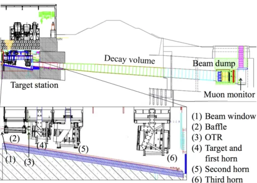
Figure 3: Overview of the neutrino beamline.
There are three sections of the primary beamline: preparation section, arc section and final focusing section (Fig. 3). The 30 GeV accelerated proton beam is extracted into the preparation section. The extracted beam is tuned the position and width with normal-conducting magnets in order to match the beam optics at the arc section. The beam is then bent toward the direction of the Super-Kamiokande by 80.7◦ using super-conducting combined function magnets at the arc section. After the arc section, the beam is tuned the position and size and focused on the center of the target with normal-conducting magnets while directing the beam downward by 3.647◦ at the final focusing section. These sections consist of the following equipment:
• normal-conducting magnets and their power supplies,
• super-conducting magnets and their power supply and cryogenic system, • beam monitors,
• beam plugs, • collimators, • vacuum system.
The beam optics and the present design of the equipment except for the beam monitor is briefly described in Sec. 2.2 to clarify which parts need modification toward higher beam power. The upgrade plan of the primary beamline is then discussed in Sec. 2.3. The present
design, operation status and upgrade plan of the proton beam monitors is then discussed in Sec. 2.4. Sec. 2.5 discusses the maintenance scenario of the primary beamline. The upgrade plan of muon monitor, which is one of important beam monitors in T2K, is described in Sec. 2.6.
2.2
Primary beamline
2.2.1
Optics
The primary beamline has been stably operated so far. Stable operation with 485 kW beam power was achieved. The beam emittance is expected to be 6∼7π mm mrad (three sigma emittance) based on the beam width measurement and the calculation of β and momentum dispersion value. The beam envelop of the present optics at 30 GeV is shown in Fig. 4.
An emittance of 10π mm mrad was assumed for the extracted beam from the MR in the design of primary beamline. Normal-conducting magnets, installed in the preparation section and in the final-focus section, and their beam ducts were designed to accept an 81π mm mrad beam envelope both in horizontal and in vertical individually with no momentum spread, and to have momentum acceptance of 2% for 10π mm mrad emittance beam. On the other hand, super-conducting magnets installed in the arc section have an acceptance of 206π mm mrad.
Figure 4: Beam envelop of the present optics at 30 GeV. The beam size is measured by beam
profile monitors (SSEM and OTR). Top (bottom) figure shows the horizontal (vertical) envelop.
∆p/p = 0.001 is assumed to calculate the beam size.
However, due to a last-minute optics re-calculation and magnet swap, the aperture of some of the magnets may be too small for the desired increase in beam power. The beam size is the largest at PQ1, the first quad after extraction, and at FQ2 and FQ3 for targeting.
Beam sizes at FQ2 and FQ3 are sensitive to the beam emittance, and if the incoming beam emittance increases for higher beam power, a larger aperture is required.
Beam optics tuning is regularly performed when the MR beam power or the beam param-eters is changed. It is important to keep the neutrino beam direction stable within 1 mrad because the neutrino energy peak can be shifted. In order to keep the beam direction stable, the beam position on the target is carefully tuned at the center with checking the measured beam position at the muon monitor. The beam direction is also confirmed by INGRID beam profile measurements. Beam size at the target surface is also tuned to keep 4mm of a gaussian standard deviation for both horizontal and vertical by adjusting the magnetic force of the four quadrupole magnets at the final-focusing section in oder to keep the targeting efficiency high enough while minimizing the thermal stress in the target. Understanding of the momentum dispersion is important. At the recent high power operation, ∼ 0.1% of the momentum spreading is observed at the MR. On the other hand, there is a finite dispersion on the horizontal direction. In order to keep fluctuation of the horizontal beam position and size small, the horizontal momentum dispersion is required to keep less than 1m during the beam optics tuning based on the optics model calculation.
2.2.2
Beam loss
The beam loss is measured by fifty of the beam loss monitors installed along the primary beamline. The monitor is a wire proportional counter filled with an Ar-CO2mixture. Fig. 5
shows the beam loss distribution along the primary beamline. The residual radiation dose is also regularly measured. It has been found that the residual dose is within the manageable level although the residual radiation does at the most upstream part of the preparation section is large even at 485 kW operation. One of these causes could be the small aperture of the steering magnet placed at the most upstream of the preparation section (PV1) and the beam halo from the MR causes the beam loss.
Figure 5: Beam loss distribution and residual radiation level along the beamline at the present
running conditions with 480 kW. Horizontal axis is the distance from the extraction point.
The assumed maximum beam loss at the primary beamline is 750 W point loss at any location of the preparation section, 1 W/m line loss at the arc section and 250 W point loss at any location of the final-focus section to determine the radiation shield thickness. It is not meant to operate the primary beamline with the above beam loss continuously since the equipment is designed based on the hands-on maintenance scenario with semi-remote or quick action devices.
2.2.3
Normal-conducting magnets
The preparation section and the final-focus section consist of 11 and 10 normal-conducting magnets, respectively. The parameters are summarized in Tab. 3.
Table 3: Summary of normal conducting magnet parameters.
The length, and hence the BL, of the preparation section magnets are designed for 50 GeV proton beam while those of the final-focus section magnets are designed for 40 GeV beam in term of the capability of cooling water system and electricity. The original power supplies, reused from the KEK 12 GeV PS, were capable of 50 GeV operation. This system was replaced in 2014, since we faced difficulty in obtaining maintenance parts, by new power supplies designed for 30 GeV operation. This change in the design proton energy originates from the change of the MR energy goal.
At the design stage, large beam loss of about 1 MGy/year was forecasted at the upstream part, close to the fast-extraction point. Therefore upstream magnets are made with mineral-insulated coils or polyimide-mineral-insulated coils. These have radiation resistance up to 1011 Gy
and 4×10⁸Gy, respectively [9]. On the other hand, downstream magnets are made of
epoxy-insulated coils, which has radiation resistance up to 107Gy. Beam loss at 480 kW operation at present is estimated to be order of 0.1 W/magnet, which is two-orders of magnitude smaller than the assumption at the design stage. Therefore even epoxy-insulated coils are expected to survive the higher beam power operation.
2.2.4
Super-conducting magnets
The beam is bent by 80.7◦ using super-conducting combined function magnets [10, 11, 12,
13, 14] at the arc section. These magnets are the world’s first combined-function super-conducting magnets, consisting of 14 doublets (focus/defocus) and 3 pairs (normal/skew) of steering magnets. With an inner diameter of the coil of 173 mm, they are capable of generating a 2.6 T dipole field with a 19 T/m quadrupole field to bend 50 GeV protons towards the Kamioka direction with a radius of 104 m, together with 8000 A power supply. The cooling power of the cryogenic system is 1.2 kW.
The heat load due to beam loss is assumed to be 1 W/m, or 150 W in total for the 150 m long section, which is small enough compared to the cooling power. The beam loss
of 1 W/m corresponds to 1 MGy irradiation on the coil for 30-years operation. Endurance of the material against this irradiation was established by gamma-ray irradiation test.
2.2.5
Vacuum system
In order not to have beam windows at the boundaries of the MR and the super-conducting section, the beamline vacuum of the preparation section and of the final-focus section is designed to achieve a level of 10−6Pa at the boundaries. This is achieved by four ion pumps (IP) at each section. At the beginning, the final-focus section was equipped with two turbo-molecular pumps (TMPs) not to shorten lifetimes of the ion pumps due to out-gassing from the most downstream monitor stack. In 2013, the TMPs were replaced with IPs in order to avoid to exhaust any fragments if the beam window at the end of the primary beamline is broken.
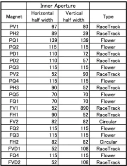
The beam ducts are designed to have an 81π mm mrad aperture in both the emittance of horizontal and vertical plane for dipoles and an 81π mm mrad ellipse for quadrupoles except for a few magnets (PV1 and FQ3) due to last-minute location swap and optics re-calculation, respectively. The apertures of the beam ducts are summarized in Tab. 4.
Table 4: Summary of apertures of the beam ducts. The unit of inner aperture is millimeter
(mm).
In order to withstand the thermal shock stress due to a direct hit of a mis-steered beam, the beam duct material should be either titanium or aluminum, based on the simulation results summarized in Tab. 5. There are still a few beam ducts made of 3 mm thick stainless steel in some steering magnets (PH3, FH1, FV1 and FV2) due to financial reasons. These will be replaced with the titanium beam duct before going beyond 2 × 10¹⁴ ppp.
2.2.6
Collimator
The initial purpose of the collimators is to scrape off the beam halo. Four sections were reserved for the collimators at the preparation section for later installation after obtaining the actual beam halo characteristics.
Observations during beam operation indicate that beam loss is not large. On the other hand, fast-extraction magnet failures occasionally happens. This trip results in off-orbit beam coming into the primary beamline and may hit the target off-center, or may hit the beam ducts, or may hit the super-conducting magnets in the worst case. Presently two
Table 5: The simulation results of the thermal shock on the beam duct with direct one-shot hit
of 50GeV 750kW beam with 3.3 × 10
14ppp[15].
Duct material
Thickness
Energy deposit
∆T
Stress
Maximum Strength
SUS
5 mm
150 kGy/pulse
290 K
1.0 GPa
∼ 520 MPa (SUS 304)
3 mm
120 kGy/pulse
230 K
840 MPa
Al-alloy
5 mm
60 kGy/pulse
70 K
100 MPa
∼ 310 MPa (Al-alloy 5056)
3 mm
60 kGy/pulse
70 K
100 MPa
pure-Ti
5 mm
100 kGy/pulse
190 K
170 MPa
∼ 550 MPa (JIS-3)
3 mm
80 kGy/pulse
150 K
130 MPa
∼ 390 MPa (JIS-2)
collimators are installed, PC1 and PC4. The primary purpose of these collimators is not to scrape off the beam halo but to block the off-center beam orbit in the case of a magnet trip. The aperture of the collimators, shown in Tab. 6, are determined to block such off-center beam to protect important beamline components. The effect was actually verified by scanning the beam position with very low intensity beam.
Table 6: Summary of apertures of the collimators. The second column is the distance from a
gate-valve which placed the boundary between MR and neutrino beamline.
Entrance half aperture
Exit half aperture
Name
Distance [mm]
x [mm]
y [mm]
x [mm]
y [mm]
PC1
28492
63
33
63
33
PC2
31895
No installation plan at present
PC3
36842
No installation plan at present
PC4
46162
31
33
33
30
Since the beam loss at the collimators is not large, they are cooled by conduction to the shielding iron wall at present.
2.2.7
Beam Plug
A pair of beam plugs are installed at the upstream part of the preparation section for the human safety purpose, namely to prevent the beam accidentally being injected to the primary beamline when the downstream neutrino facility is being accessed.
The structure of the beam plug is shown in Fig. 6. The upstream block is made of 20 layers of 10 mm-thick stainless steel plates with 5 mm gap, and the downstream block is made of 15 layers of 20 mm-thick stainless steel plates. With this 50 cm-thick stainless steel, MARS simulation gives the radiation level less than 0.1 µSv at the end of the primary beamline when one shot of 50 GeV 750 kW beam hits the beam plug. This ensures the safety of the access to the target station when the MR is in operation, provided that both the blocks of the beam plug are inserted into the beam line and the safety magnets (two bending magnets PD1 and PD2) are kept off. The blocks are made of thin plates to relax the thermal shock stress when the beam hits the beam plug. The upstream block has gaps between the plates to further relax the stress by defusing the beam distribution. The thermal shock stress was simulated using GEANT. Shower maximum, and thus the highest energy density, locates in the first block as shown in Fig. 7. Using the expected beam spot of 2 cm2 at the beam plug, if the blocks are hit by 30 GeV proton beam with 2 × 10¹⁴ppp,
the expected protons per pulse at 750 kW operation, the maximum thermal shock stress is calculated to be 440 MPa, slightly below the tensile strength of stainless steel, 520 MPa. Here we used thin-plate approximation formula with adiabatic condition and sharp-edged
circular beam spot;
σ = E · α · ∆T · f (β)
(1 − ν) (1)
where σ is the maximum thermal shock stress at the beam spot edge, E is the Young’s modulus, α is the thermal expansion coefficient, ∆T is the temperature rise, ν is Poisson’s ratio, and f (β) is a geometry factor to be 0.4 at the Biot’s coefficient β = ∞, with considering a stress at the surface at cylinder heated from the beam hit and then 1/σ∗
max = 2.5 from
Fig. 8 which corresponding to 1/f (β).
Figure 6: Design of the beam plug.
Figure 7:
The shower development in
the beam plug simulated by GEANT for
40 GeV proton hit.
Figure 8: Relationship between Biot’s
co-efficient β and maximum thermal shock
stress σ
max.
2.3
Upgrade plan of the primary beamline
The primary beamline is basically capable of accepting 1.3 MW beam power provided that beam loss is kept low as the present level.
2.3.1
Beam optics and larger aperture magnets
The beam loss of the most upstream part of the preparation section, and hence the residual radio-activation, is large even at 485 kW operation. One of these causes could be that PV1 magnet does not have 81π mm mrad in the horizontal direction as shown in Fig. 9 and the beam halo from the MR causes the beam loss. The final-focus quadrupole doublets, FQ2 and FQ3, may also need to enlarge their aperture (present size is 150 mm) for the large
emittance beam at the higher ppp. Figure 10 shows the 81π mm mrad beam size at FQ2, 3, 4 for the 10π mm mrad emittance beam, and Fig. 11 shows the beam envelope for the 24π mm mrad emittance beam. The aperture of the FQ3 is very tight even at 10π mm mrad beam, and the larger emittance beam may result in intolerable beam loss. The quadruple magnets with the aperture of 200 mm such as PQ1 are one candidate.
Figure 9: Beam size and aperture of PV1.
Figure 10: 81π mm mrad beam size at FQ2,
3 and 4.
The beam halo could depend on the MR beam power as well as the MR larger aperture magnet installation plan. The MR plans to increase the beam power by installing the MR main power supply by 2021, and upgrading the MR RF by 2026. The beam halo should be evaluated with higher protons per bunch (ppb) even before the main power supply and the RF installation. The beam study before these installation is planned to evaluate the beam loss at the neutrino primary beamline caused by the beam halo. The ppb is gradually increased up to 4 × 10¹³ppb, which is the ppb at 1.3 MW, and the number of bunch is kept to be 2 bunch because the 8 bunch operation requires the RF upgrade.
The design of the larger aperture magnets, PV1, FQ2 and FQ3, will be ready by 2020 based on the MR larger aperture magnet plan and the results of the beam study of the higher ppb beam. The fabrication of these magnets is planed to start on 2021 and therefore the summer of 2022 is the earliest installation. This strategy can accommodate the 1 MW beam, which is expected before 2022, because the present aperture magnet was able to accept the 510 kW (corresponding to 3.3 × 10¹³ ppb) without any significant beam loss at
the neutrino primary beamline.
The aperture of the super-conducting magnets are large enough to accept the beam without significant beam loss even at 1.3MW.
2.3.2
Collimator
The collimators have a much smaller aperture compared to the magnets in order to block the off-orbit beam. Therefore they are very sensitive to the beam tail. At 485 kW operation, the beam halo is not significant. The collimators are not scraping off the halo and the heat load is negligible. The 750 kW operation will be achieved by simply increasing the repetition rate, and no significant increase of the heat load is expected. The 1.3 MW operation, however,
Figure 11: Beam evenlope at FF section for 24π mm mrad.
needs an increase of the protons per pulse, and the beam halo condition may drastically change. Our operation principle is, however, even at beyond 750kW, to keep the beam loss at the present level so as not to increase the residual radiation of the primary beam-line equipment for sustainable maintenance scenario.
2.3.3
Beam plug
The present beam plug can withstand the beam injection up to 750 kW. For the larger ppp beyond 750 kW, we need to replace the first block with an Invar plate. An aluminum or a titanium plate also gives much smaller stress, but densities are too low to accommodate in the present vessel.
Thermal stress for Invar was also simulated by GEANT. For bulk Invar, the maximum sigma is 308 MPa. For 20 layers of 1cm thick Invar plates with 1cm gap, maximum sigma is 121 MPa The yield strength of Invar is 400 MPa. Stress at the actual configuration be between above two, probably closer to 121 MPa.
2.4
Proton beam monitors
The proton beam conditions are continuously monitored by a suite of proton beam monitors along the neutrino primary proton beamline, as shown in Fig. 12 and described in Ref. [16]. Five Current Transformers (CTs) are used to continuously monitor the proton beam intensity. Fifty Beam Loss Monitors (BLMs) continuously measure the spill-by-spill beam loss and are used to fire an abort interlock signal in the case of a high loss beam spill. Twenty-one Electro-Static Monitors (ESMs) are used as Beam Position Monitors to continuously monitor the beam position and angle.
So far, these monitors have been running well with the design precision and stability. These monitors were all designed to work continuously at high intensity (3.3 × 10¹⁴protons
Figure 12: Location of the beam monitors in the J-PARC neutrino beamline.
for the foreseeable future. Regular calibration, improvements in calibration methods, and analysis improvements may be necessary for maintaining or improving the monitor stability or precision, and these will be carried out as needed.
The proton beam profile (beam position and width) is monitored bunch-by-bunch dur-ing beam tundur-ing by a suite of 19 Segmented Secondary Emission Monitors (SSEMs) [16] distributed along the primary beamline, where only the most downstream SSEM (SSEM19) is used continuously. An Optical Transition Radiation Monitor (OTR) [17], placed directly upstream of the production target, also continuously monitors the beam profile spill-by-spill. Other beam parameters, such as the beam angle, twiss parameters, emittance, etc, at the position of the baffle and target, are extrapolated by a fit to several downstream SSEMs and the OTR during beam tuning. The beam position and angle at the target is continuously monitored spill-by-spill by a fit to several ESMs, SSEM19 and the OTR during standard running, while the other proton beam parameters are extrapolated by scaling the data from SSEM-IN runs with spill-by-spill SSEM19 and OTR information when the other SSEMs are OUT.
Potential issues with the SSEMs are described in Sec. 2.4.1 and a plan to upgrade SSEM18 is described in Sec. 2.4.2. Recent OTR issues and plans for OTR upgrades are discussed in Sec. 2.4.3. An ambitious profile monitor upgrade project – development of a continuous, non-destructive Beam Induced Fluorescence (BIF) beam profile monitor – is also described in Appendix A.1.
2.4.1
Segmented Secondary Emission Monitor (SSEM)
Each SSEM sensor head consists of two thin (5 µm, 10−5 interaction lengths) titanium foils stripped horizontally and vertically (to measure the vertical and horizontal beam profiles respectively), and an anode HV foil between them, as shown in Fig. 13. The strips are hit by the proton beam and emit secondary electrons in proportion to the number of protons that go through the strip, and compensating charge in each strip is read out as a pulse with positive polarity. The proton beam profile is reconstructed from the resulting charge distribution from all strips on a bunch-by-bunch basis. The strip width of each SSEM ranges from 2 to 5 mm, optimized according to the expected beam size at the installed position, and the gap between strips is 1 mm.
The precision of the SSEM position and width measurements are 0.07 mm and 0.2 mm respectively. The SSEM profile monitors are designed to work at high beam intensity (∼3 × 10¹⁴ ppp), and so far there have been no major issues with the stability and precision of
these monitors.
Each SSEM causes 0.005% proton beam loss while in the beam. Therefore, the monitors can be remotely moved into and out of the beamline to eliminate additional loss during standard running. Eighteen of the SSEMs are only used to check the beam profile during
Figure 13: Principle behind SSEM sensor design (left) and diagram of the SSEM sensor head
used in the J-PARC neutrino beamline (right).
beam tuning or after some expected parameter change, while the most downstream SSEM (SSEM19) and the OTR, which are located inside the monitor stack and Target Station respectively, and therefore in a high-radiation environment already, are used continuously. The beam width continuously measured by SSEM19 is used to protect the beam window and target : if the beam density (number of protons/beam spot size) at the target becomes Np/(σx×σy) < 2×10¹³ppp/mm2, a beam abort interlock is fired in order to avoid potential
damage. The beam position, angle, width, etc. measured spill-by-spill are also used as an input into the T2K neutrino flux prediction.
Figure 14: Observed secondary emission of SSEM19 over the full T2K run so far. Jumps in
normalized secondary emission appear to be correlated with changes in beam power. Points are
shown when the other SSEMs are OUT (black) and IN (red).
Since bunch-by-bunch (and spill-by-spill) information from SSEM19 is necessary for T2K, potential degradation of the secondary emission signal should be carefully monitored. The recent light yield vs. POT for SSEM19 is shown in Fig. 14. A potential ∼20% decrease in the secondary emission of SSEM19 has been observed after an integrated 2.3 × 10²¹POT (with
an average beam spot size of 4 x 4 mm), although the secondary emission stability at stable beam power (after an initial burn-in period) appears to be very good. The expected SSEM lifetime is not precisely known, however studies by both J-PARC and CERN have indicated
Figure 15: Change in the secondary emission efficiency of aluminum and titanium foils in the
CERN SPS beam line [18].
that the secondary emission efficiency of titanium is stable up to 1018protons/cm2, as shown in Fig. 15. Although this integrated POT has already been exceeded at T2K, Fig. 14 shows that the SSEM19 secondary emission is basically stable after an integrated 1 × 10²¹ POT. However, SSEM19 should be periodically replaced if degradation begins to occur, and the first SSEM19 replacement is currently planned for summer 2019 or 2020.
Since the SSEMs other than SSEM19 (SSEM1-18) have a relatively low total integrated incident number of protons, no issue with degradation is expected for SSEM1-18. SSEM1-18 are also installed in the primary beamline, which is much easier to access then the monitor stack (where SSEM19 is installed). Therefore, the SSEM1-18 sensor heads can be relatively easily replaced by spares if any issues do occur.
2.4.2
Wire Secondary Emission Monitor (WSEM)
Beam loss due to interactions in material placed into the beam is proportional to the volume of material in the beam. On the other hand, secondary emission is proportional to the surface area in the beam. Therefore, the original SSEM beam profile monitors used 5-µm-thick stripped foils to maximize interaction rate and minimize beam loss. Each monitor head consists of 3 foils.
Beam loss from these profile monitors can be reduced by switching from foils to wires intercepting the beam. A new Wire Secondary Emission Monitor (WSEM), one plane of which is shown in Fig. 16, has been jointly developed with the monitor group FNAL as part of the US/Japan collaboration, and prototype planes were built for the J-PARC primary neutrino beamline. This monitor consists of 2 planes with 25µm diameter twinned pure Ti (Grade 1) wires with 3 mm pitch. An anode plane between them, consisting of of 25µm single Ti wires with a 2- or 6-mm pitch, can be set to 100 V to sweep away electrons. All wires were mounted to the ceramic frame under a tension of 20 g/wire. The expected and measured signal size and beam loss for the WSEM compared to the standard SSEM is given in Table 7.
A prototype WSEM monitor has already been fabricated and installed for testing in the neutrino primary beamline.
The WSEM wires are mounted at 45◦with respect to the square ceramic frame in order to allow for a c-shape cutout design, while the anode plane wires are mounted aligned to the square frame. This c-shape allows for motion of the monitor into and out of the beam during beam running (allowing for automated, periodic checks of the beam profile when used in non-continuous mode). This means that the monitor must be mounted at 45◦ on the beampipe, requiring a mover also mounted at 45◦. For testing, the WSEM was mounted on a spare standard J-PARC SSEM mover resting on a modified 45◦ stage, however an
Figure 16: WSEM frame with mounted electron collection anode plane (vertical wires) and one
set of cathode wires (diagonal wires).
Table 7: SSEM vs WSEM parameters calculated assuming 3mm diameter beam spot size and
measured during a beam test. Note that test conditions differ slightly between the monitors, as
discussed in the text.
Monitor
Strip Size
Area in
Measured
Volume in
Measured
Beam (mm
2)
Signal (a.u.)
Beam (mm
3)
Loss (a.u.)
SSEM
2∼5mm×5µm
7.07
60300
0.106
872
WSEM
25µm
x2
0.24
2300
0.007
112
Ratio
SSEM/WSEM
–
29.5
26
15.1
7.8
improved mover design, which moves the WSEM readout cables at the same time as the sensor head and should allow for more reliable use of the WSEM, was also prepared in JFY2017.
In beam tests, the beam loss was measured to be ∼8x lower for the WSEM than for the neighboring SSEM05, as shown in Fig. 17. However, the Beam Loss Monitor acceptance is different for the two monitors and is actually slightly higher for the WSEM, such that the actual reduction in total loss is greater than a factor of 8. The beam position and width measured by the WSEM matches those measured by the neighboring monitors (SSEM05 and SSEM06), as shown in Figs. 18 and 19, although a full analysis procedure for the WSEM data is still under development.
Figure 17: Measured beam loss due to WSEM vs neighboring SSEM.
Beyond signal checks, extensive robustness testing of the WSEM has also already been carried out – the WSEM was left in the high intensity (460∼475 kW) proton beam for ∼160
Figure 18: Horizontal beam profile measured by the WSEM (left) and neighboring SSEM05
(right). Note that the horizontal axis ranges are different and the WSEM absolute alignment
calibration is not applied.
Figure 19: Beam position (left) and width (right) measured by WSEM and neighboring SSEMs
at low beam intensity.
hours without any observed issues. Heating of the wires in the J-PARC proton beam is expected to be very modest compared to the temperature rise required for a substantial change in Ti yield strength, as confirmed by this beam test.
Currently only SSEM19 can be used continuously, since it is in the Target Station mon-itor stack where radiation shielding and remote handling procedures are already in place. SSEM19 is essential for monitoring the beam profile spill-by-spill. Since the beam loss due to the WSEM is ∼0.0005%, this monitor may be suitable to leave in the beam at all times even outside the Target Station. The residual radiation level due to using the WSEM continu-ously was 300µSv/hr on contact directly downstream of the WSEM after 150 h in the beam (measured 6 hours after beam stop). The residual radiation level on contact downstream of SSEM18 is 1.2mSv/hr after continuous running at 475 kW due to backscatter from the Target Station.
The present plan is to replace SSEM18 with a WSEM during summer 2018 and use the WSEM as SSEM18 is currently used (ie periodically insert it during beam tuning). In the case that SSEM19 becomes unusable, the WSEM can be used continuously. If the performance of the WSEM proves to be better than an SSEM, we may opt to replace other SSEMs with WSEMs in the future. Further long-term testing of the WSEM performance will be possible with the WSEM installed at the SSEM18 position. As described in Sec. 2.5, a new semi-remote maintenance scheme for the most downstream part of the FF beamline will also be prepared within 2018. With this new maintenance scheme, if there is any trouble with the WSEM, replacement of the WSEM monitor head will be much easier at the SSEM18 position compared to at the SSEM19 position inside the monitor stack.
WSEM Schedule
The schedule for the WSEM testing and installation is as follows : • JFY2015 : WSEM prototype was designed and fabricated at FNAL• JFY2016 : WSEM was mounted on J-PARC NU beamline and preliminary beam tests were performed
• JFY2017 : Further beam tests were carried out. An improved mover for the WSEM was designed jointly with FNAL experts
• JFY2018 : New mover will be built. WSEM will be installed in the SSEM18 position during the summer shutdown, if schedule permits
• JFY2019 summer : WSEM will be installed in the SSEM18 position, if not done during 2018
2.4.3
Optical Transition Radiation Monitor (OTR)
The OTR uses optical transition radiation, light emitted from a thin metallic foil when a charged beam passes through it, to form a 2D image of the proton beam directly upstream of the neutrino production target.
The OTR active area is a 50-µm-thick titanium-alloy foil, which is placed at 45◦ to the incident proton beam. As the beam enters and exits the foil, visible light (transition radiation) is produced in a narrow cone around the beam. The light produced at the entrance transition is reflected at 90◦ to the beam and directed out of the Target Station (TS) He vessel by four aluminum 90◦off-axis parabolic mirrors to an area with lower radiation levels. It is then collected by a charge injection device (CID) camera to produce an image of the proton beam profile spill-by-spill.
The precision of the OTR position and width measurements are better than 0.8 mm in X and 0.5 mm in Y. According to mechanical strength simulations, the OTR is designed to work at high beam intensity and should be able to withstand 3.3 × 10¹⁴ppp. So far there has been only one issue with the OTR beam profile measurement. The OTR position measurement in X drifted by 2 mm between 12 March and 1 April 2015, although measurement of upstream proton beam monitors didn’t drift during the same time period. The drift is compatible with a movement of the CID camera or the OTR foil moving in the direction of the proton beam. The cause of the drift is still unknown.
The recent light yield vs. POT for the OTR is shown in Fig. 20 – a decrease in the OTR light yield of ∼75% after an incident 2.0 × 10²¹ protons has been observed. Potential
degradation of OTR monitor foils can be mitigated by having multiple available OTR foils, as described below.
Figure 20: Observed OTR light yield degradation.
The OTR monitor consists of an arm holding a disk which is an 8-position carousel, shown in Fig. 21. The OTR disk currently holds :
• Four 50-µm-thick Ti 15-3-3-3 (15% V, 3% Cr, 3% Sn, 3% Al) foils
• One 50-µm-thick Ti 15-3-3-3 foil with 30 holes in a grid pattern for calibration • One 50-µm-thick Ti 15-3-3-3 “cross foil” with twelve holes in a cross pattern
• One ceramic (fluorescent) foil for low-intensity running • One empty position
Figure 21: Front (left) and back (right) of OTR disk.
The OTR disk is rotated by a long rigid steel shaft which couples to a flexible steel shaft that follows a 90 degree bend to the arm supporting the foil disk. A spline coupling is made at the end of the arm to another flexible shaft which runs along the arm and connects to the disk. The motor is connected to the shaft through a 100:1 gearbox, so that the disk rotates slowly. The foil position can be determined in principle by counting the number of motor steps using its encoder, however, due to backlash in the flexible shaft system, alternate methods of ensuring precise foil positioning are necessary. The primary method to change foil positions is to run the motor until it is turned off by a micro-switch (model 6302-16 from Haydon, designed for extreme conditions) engaged by a machined titanium button on the disk. The switch position has been adjusted so that it engages the button just before a foil is in the correct position. A steel ball-bearing plunger mechanism, spring-loaded against the surface of the disk, then falls into a matching machined depression in the disk flange, which locks it firmly into the correct position for each foil. Most of these features can be seen in Fig. 21. When the motor is turned on again to move to the next foil position, the torque of the motor and shaft system is sufficient to start rotating the disk and bring the ball bearing out of the depression against the spring force. The foil position repeats with this method to 0.1 mm precision. A backup system uses a pressurized helium gas line, which ends in a brass tube with an end face parallel to the back of the disk about 0.1 mm from the surface (see Fig. 21). As the disk rotates the He pressure is maintained until the correct foil position is reached, at which point the tube end encounters a hole through the disk, reducing the pressure. This method is precise only to ∼2 mm, but sufficient to double-check the position of a foil in the beam in the case of failure of the micro-switch. This same helium line can be used to remove any accumulated dust from the foils, since the gas passing through the hole in the disk is guided by a custom nozzle to blow across the foil surface.
The OTR operation history is as follows : • OTR-I
– Built and installed in 2008∼2009 – Stable operation 2009∼2013 • OTR-II
– Built in 2009 and stored as spare of OTR-I
– Operation between May 2014∼present – Minor problems from Mar. 2015 (see below)
– Motor disconnected and OTR disk fixed at cross foil position since Jan. 2016 • OTR-III
– Present spare system built in 2013
– Assembled, calibrated and tested in 2014 together with OTR-II
– Exchange rehearsal using the manipulator arm system in the remote maintenance area performed in Dec. 2015
– Disk flange and plunger are being re-designed (see below) – Ti foils to be modified
∗ Additional holes will be drilled in the Ti foils
∗ However, the exact hole pattern is currently still under consideration – foil mechanical strength and usefulness for optical calibration must be balanced – Plan to remove OTR-II and install OTR-III in summer 2018
• OTR-IV
– Built identical to OTR-III
– Plan to use it as spare of OTR-III
Although the disk was originally designed for frequent rotations, there have been some recent issues with the rotation mechanism, as described below, and the disk is currently being kept in a single position. The cross foil is now in use for beam running, since that foil may be used to both measure the beam profile, and the holes allow for periodic check of the OTR alignment and calibration by back-lighting. Future versions of the OTR will have holes for periodic monitoring of the alignment on each of the Ti foils.
So far, the cross foil has seen ∼2.0×10²¹POT, as shown in Fig. 20. Gradual degradation
of the OTR light yield as a function of POT has been observed. Most of this yield decrease is probably due to radiation-induced darkening of a leaded glass fiber taper coupled to the CID camera, and <20% due to the visible darkening of the foil.
OTR Disk Rotation Issue
Although the OTR disk was originally designed for many rotations in order to frequently switch between the different foils, issues with the disk rotation mechanism have been observed. For OTR-II, it was found that after many disk rotations, the plunger mechanism becomes stiff such that it becomes difficult for the plunger to disengage from the hole, making rotations in one direction by the motor impossible. However, it was found that rotations where the disk is moved backwards worked fine.One possible cause of this issue is that the plunger became rusted since the ball and its housing was made of the common 304 stainless steel (SS). Because of this, the ball may not be able to rotate properly and more torque from the motor is needed to disengage it from the hole. The non-rotating ball can also cause mechanical damage to its housing and the disk flange made of titanium which is not as hard as 304 SS.
Test bench tests have shown a similar issue in a non-radiation environment, although those tests show that rotation in both directions is affected.
A new custom plunger and disk flange have been designed and tested for OTR-III and OTR-IV. The new custom plunger ball and housing was made of 440C SS heat-treated to a hardness of 55-60 Rockwell C. The ball now fits better to the plunger internal diameter and an external screw was included to adjust the plunger’s spring force. The new disk flange was made of 440C SS to prevent mechanical damage during disk rotation. The new design was tested and works stably for >100 rotations without any change in rotation torque.


![Figure 68: Temperature dependence of aluminum alloy A6061-T6 tensile strength. Data points are taken from [27].](https://thumb-eu.123doks.com/thumbv2/5dokorg/4270500.94725/64.892.218.668.487.783/figure-temperature-dependence-aluminum-alloy-tensile-strength-points.webp)
