Degree project in
Communication Systems
Communication Systems, 30.0 HEC
Stockholm, Sweden
I S A A C A L B A R R Á N
a n d
M A N U E L P A R R A S
Network Performance analysisMigration to the Cloud
K T H I n f o r m a t i o n a n d C o m m u n i c a t i o n T e c h n o l o g y
Cloud
Network Performance analysis
Isaac Albarrán Manuel Parras
29 April 2012
Master’s Thesis at the School of Information and Communication Technology (ICT)
KTH Royal Institute of Technology Stockholm, Sweden
ISAAC ALBARRÁN MANUEL PARRAS Master Thesis
Academic supervisor: Gerald Q. Maguire Jr.
Industrial supervisors: Leif Y. Johansson and Nikhil Tikekar Registration number: TRITA-ICT-EX-2012:54
©2012 ISAAC ALBARRÁN and MANUEL PARRAS
School of Information and Communication Technology (ICT) KTH Royal Institute of Technology
SE-100 44 Stockholm Sweden
Abstract
Nowadays, telecommunication services are commonly deployed in private networks, which are controlled and maintained by the telecommunication operators themselves, by co-location services providers, or, to some extent, by their hardware and software providers. However, with the present development of cloud computing resources, one might consider if these services could and should be implemented in the Cloud, thus taking advantage of cloud computing’s high availability, geographic distribution, and ease of usage. Additionally, this migration could reduce the telecommunication operators’ concerns in terms of hardware and network maintenance, leaving those to the Cloud computing providers who will need to supply a highly available and consistent service, to fulfill the telecommunication services’ requirements. Furthermore, virtualization provides the possibility of easily and rapidly changing the Cloud network topology facilitating the addition and removal of machines and services, allowing telecommunication services providers to adapt to their demands on the fly.
The aim of this thesis project is to analyze and evaluate the level of performance, from the network point of view, that can be achieved when using Cloud computing resources to implement a telecommunication service, carrying out practical experiments both in laboratory and real environments. These measurements and analyses were conducted using an Ericsson prototype mobile switching center server (MSC-S) application, although the results obtained could be adapted to other applications with similar requirements.
In order to potentially test this approach in a real environment, a prior providers’ survey was utilized to evaluate their services based on our requirements in terms of hardware and network characteristics, and thus select a suitable candidate environment for our purposes. One cloud provider was selected and its service was further evaluated based on the MSC-S application requirements. We report the results of our bench-marking process in this environment and compare them to the results of testing in a laboratory environment. The results of both sets of testing were well correlated and indicate potential for hosting telecommunication services in a Cloud environment, providing the Cloud meets the requirements imposed by the telecom services.
Resumen
Actualmente, los servicios de telecomunicaciones se implementan comúnmente en redes privadas, controladas y mantenidas por los operadores de telecomunicaciones, por proveedores de servicios de colocación o, hasta cierto punto, por proveedores de hardware y software. Sin embargo, con el presente desarrollo de la tecnología de ’Cloud computing’, se puede considerar la posibilidad de implementar servicios de telecomunicaciones en la nube, aprovechando su alta disponibilidad, distribución geográfica y facilidad de uso. Además, este cambio puede reducir las preocupaciones de los operadores en relación al mantenimiento del hardware y de la red, delegando en los proveedores del servicio de ’Cloud computing’, los cuáles deberán proporcionar un servicio consistente, cumpliendo así con los requisitos de los servicios de telecomunicaciones. Por otra parte, la virtualización propociona la posibilidad de cambiar rápida y fácilmente la topología de la red, facilitando la adición y supresión de maquinas y servicios, y, por tanto, permitiendo a los operadores adaptarse a sus necesidades sobre la marcha.
El objetivo de esta tésis es analizar y evaluar en nivel de rendimiento, desde el punto de vista de la red, que se puede conseguir usando recursos de ’Cloud
computing’ para implementar un servicio de telecomunicaciones, llevando a
cabo experimentos tanto en el laboratorio como en un entorno real. Estos análisis fueron realizados utilizando un prototipo de un servidor de conmutación móvil (MSC-S) de Ericsson, aunque los resultados pueden adaptarse a otras aplicaciones con unos requisitos similares.
Para probar esta propuesta en un entorno real, se realizó una encuesta de proveedores de servicios de ’Cloud computing’, con el objetivo de evaluar sus servicios teniendo en cuenta nuestros requisitos de hardware y red. Finalmente, un proveedor fue escogido y su servicio evaluado basándonos en los requisitos de la aplicación MSC-S. En este documento proporcionamos los resultados de esa evaluación y los comparamos con los obtenidos en el laboratorio. Los resultados de ambas evaluaciones fueron satisfactorios e indican la posibilidad de implementar servicios de telecomunicaciones en la nube, siempre que la nube cumpla los requisitos impuestos por dichos servicios de telecomunicaciones.
Sammanfattning
Nuförtiden är telekommunikationstjänster ofta uppsatta i privata nät-verk, som kontrolleras och underhålls av teleoperatörerna själva, av samlo-kaliserande tjänsteleverantörer eller i viss utsträckning av deras hårdvaru-och programvaru-leverantörer. Med den nuvarande utvecklingen av Cloud Computing-resurser kan man dock överväga om dessa tjänster kan och bör genomföras i ett Cloud, vilket drar fördel av Cloud Computings höga tillgänglighet, geografiska spridning, och enkla användning. Denna migration minskar även teleoperatörernas oro angående hårdvaru- och nätverks-underhåll genom att överlåta detta till Cloud Computing-leverantörerna, som kommer att behöva leverera en hög tillgänglighet och konsekvent service för att uppfylla telekommunikationstjänsternas krav. Dessutom ger virtualisering möjlighet att enkelt och snabbt ändra ett Clouds nätverkstopologi, vilket underlättar tillägg och borttagning av maskiner och tjänster, vilket hjälper teleoperatörer att snabbt anpassa sig till deras krav.
Målet med examensarbetet är att analysera och uppskatta prestandan, från nätets perspektiv, som kan uppnås vid användning av Cloud Computing-resurser för att genomföra en teletjänst, genom praktiska experiment både i laboratorium och i verkligheten. Dessa mätningar och analyser utfördes med en prototyp av en Ericsson mobilomkopplingscentralserverapplikation (MSC-S), även om de erhållna resultaten skulle kunna anpassas till andra program med liknande krav.
För att potentiellt kunna testa denna metod i en verklig miljö användes en tidigare leverantörs undersökning för att utvärdera deras tjänster baserat på våra krav på hårdvara och nätverksegenskaper, och genom detta välja en lämplig kandidatmiljö för våra syften. En Cloud-leverantör valdes och dess tjänster utvärderades vidare baserat på MSC-Ss applikationskrav. Vi redovisar resultatet av vår testprocess i den här miljön och jämför det med resultaten av tester i laboratoriemiljö. Resultaten från båda uppsättningarna av tester var väl korrelerade och visar på potentialen av att implementera telekommunikationstjänster i en Cloud-miljö, om detta Cloud uppfyller de kraven som ställs av telekommunikationtjänsterna.
Acknowledgements
First of all, we would like to deeply thank our Ericsson’s industrial supervisors Leif Johansson, Niklas Waldemar and Nikhil Tikekar. They entrusted us with this amazing and innovative project and supported us in every step. They also contributed to our work with their great expertise in the area, and taught us many things that will be essential in our future professional career as engineers.
We would also like to sincerely thank professor Gerald Q. "Chip" Maguire Jr. for accepting to be our academic tutor and examiner, and showing such a great interest in the subject of this master’s thesis. We would also like to express our gratitude for all his support. He always answered our questions rapidly and precisely, and provided us with very useful feedback that improved the quality of our work.
Manuel:
My sincerest appreciation to my friends of Spain who have been supporting me as always in spite of being far away from home.
I additionally want to extend my thanks to all the people who have accompanied me in this great adventure that started in Sweden in 2010 and with who I have spent unforgettable moments, especially Itzi who has encouraged and supported me in every moment, even in the distance.
Last but not least, I want to express my greatest gratitude to my family, especially my parents Luis and María Victoria, because of their never-ending love and support; and my brothers Luis and Miguel Angel, and my sister María Victoria, since I am who I am because of them.
Without the support and encouragement of all these people, none of this would have been possible. ¡Muchas gracias! Thank you very much! Tack så mycket!
Isaac:
First of all, I would like to affectionately express my gratitude to my fiancee, Mercedes, who has been by my side from the beginning regardless of the distance between us, and has given me the strength to keep on every day.
In addition, I would like to thank my family, my parents Isaac and María Dolores, my brother Nacho, and my sister Marta, for the great support and love shown towards me, without which none of this would have been possible. Finally, I would like to thank my friends, both from Spain and those I have met during my stay in Sweden. Specially, I would like to acknowledge Manuel Parras, Daniel García, Armando Gutiérrez, and Nacho Mulas all of whom shared this important stage of my life with me, and supported me through it.
Contents IX
List of Figures XIII
List of Tables XV
List of Code Listings XVII
List of Acronyms and Abbreviations XIX
1 Introduction 1 1.1. Overview . . . 1 1.2. Problem description . . . 3 1.3. Goals . . . 4 1.4. Purpose . . . 5 1.5. Methodology . . . 5 1.6. Scope . . . 6 1.7. Limitations . . . 7 1.8. Target audience . . . 8 1.9. Thesis outline . . . 8 2 General background 11 2.1. Networking . . . 11
2.1.1. Network Layering concept . . . 11
2.1.2. Network Access layer . . . 12
2.1.3. Virtual Local Area Network (VLAN) . . . 14
2.1.4. Internet Protocol (IP) layer . . . 15
2.1.5. Transport layer . . . 17
2.1.6. Application layer . . . 18
2.1.7. Unicast, Multicast, and Broadcast . . . 19
2.1.8. Tunneling . . . 20
2.2. An approach to Cloud Computing . . . 21
2.2.1. Cloud Computing features . . . 21
2.2.2. Management responsibilities . . . 24 ix
2.2.3. Customization . . . 24
2.2.4. Service Level Agreement (SLA) . . . 24
2.2.5. Cloud Security . . . 25
2.2.6. Private, public and hybrid Clouds . . . 26
2.2.7. Cloud service types . . . 27
2.3. Telecom networks . . . 28
2.3.1. Mobile network architectures . . . 29
2.3.2. Mobile core network’s evolution . . . 33
2.4. Ericsson MSC-Server Blade Cluster . . . 37
2.4.1. Architecture . . . 38
2.4.2. Redundancy . . . 39
2.4.3. Scalability . . . 39
3 Ericsson MSC-S BC in a Cloud environment 41 3.1. Topologies . . . 41
3.1.1. The hybrid cluster . . . 42
3.1.2. The external cluster . . . 43
3.1.3. The split cluster . . . 44
3.2. Design considerations . . . 45
3.2.1. Motivations . . . 45
3.2.2. Drawbacks . . . 46
3.2.3. Conclusion . . . 47
4 Ericsson MSC-S BC lab tests 49 4.1. Test environment . . . 49 4.1.1. Stockholm laboratory A . . . 49 4.1.2. Stockholm laboratory B . . . 51 4.1.3. Canada laboratory . . . 51 4.1.4. Network configuration . . . 52 4.1.5. MSC-S blades states . . . 59 4.1.6. Testing tools . . . 59 4.2. Steady state . . . 59
4.2.1. Initial hybrid cluster test . . . 60
4.2.2. External cluster test . . . 62
4.2.3. Split cluster test . . . 67
4.2.4. Cluster scalability test . . . 73
4.2.5. Difficulties . . . 81
4.3. Fault recovery . . . 82
4.3.1. Theoretical introduction . . . 83
4.3.2. Fault recovery tests . . . 84
4.3.3. Prototyping issue . . . 91
4.3.4. Discussion . . . 92
5.1. Technical requirements . . . 93
5.1.1. Hardware requirements . . . 93
5.1.2. Network requirements . . . 94
5.2. Privacy and Confidentiality demands . . . 94
5.3. Providers . . . 94
5.4. Provider selection . . . 95
5.5. Selected provider bench-marking . . . 95
5.5.1. Testing scripts . . . 95
5.5.2. Performance and results . . . 102
6 Conclusions and future work 117 6.1. Conclusions . . . 117
6.1.1. Laboratory tests . . . 117
6.1.2. Cloud Service provider . . . 118
6.2. Future work . . . 119
Bibliography 121 A How to configure the machines used for testing 131 A.1. VPN setup . . . 131
A.1.1. Installation . . . 131
A.1.2. Configuration . . . 132
A.1.3. OpenVPN start, restart, and stop . . . 137
A.2. Stockholm lab B configuration . . . 137
A.2.1. Virtual machines setup . . . 138
A.2.2. Network configuration . . . 143
A.3. Blade configuration . . . 143
A.3.1. Network configuration . . . 143
A.3.2. Running the APZ Virtual Machine . . . 148
A.3.3. Software dump . . . 150
A.4. Cluster setup . . . 152
A.5. Add a blade to the cluster . . . 153
A.6. Remove a blade from the cluster . . . 153
A.7. Cluster tear down . . . 154
A.8. Cluster information and statistics . . . 155
A.8.1. Cluster state . . . 155
A.8.2. Blades’ processor load . . . 155
A.8.3. Cluster subscribers’ information . . . 156
A.8.4. Event reporting . . . 156
A.8.5. Alarms . . . 157
A.8.6. Print size alteration events . . . 157
A.9. Traffic generators . . . 157
A.9.1. HLR traffic generator . . . 158
A.10.Netem . . . 163
A.10.1. Installation . . . 163
A.10.2. Delay . . . 163
A.10.3. Packet loss . . . 164
A.11.Blade cluster modifications . . . 165
A.11.1. SAE data files resize . . . 165
A.11.2. Cloning timer removal . . . 167
B Ericsson MSC-S BC prototype laboratory measurements 169 B.1. External cluster measurements . . . 169
B.2. Split cluster measurements . . . 173
C Cloud Service Providers’ survey 177 C.1. First Cloud Service Providers’ selection . . . 177
C.2. Final Cloud Service Providers’ selection . . . 180
C.2.1. GoGrid . . . 180 C.2.2. Rackspace . . . 183 C.2.3. Savvis . . . 185 C.2.4. IBM . . . 191 C.2.5. Contegix . . . 193 C.2.6. Amazon . . . 195
D Selected Provider Benchmarking scripts 199 D.1. awk_udp . . . 199 D.2. awk_BW . . . 200 D.3. awk_average_RTT . . . 200 D.4. awk_loss . . . 200 D.5. awk_MAX_RTT . . . 201 D.6. awk_MIN_RTT . . . 201 D.7. awk_jitter . . . 202
1.1. Cloud computing companies . . . 3
2.1. Comparison of OSI and TCP/IP models. Adapted from figure 1 of [19]. 13 2.2. A switched Ethernet network topology (A) and the logically equivalent LAN representation (B). . . 14
2.3. Deployment of two VLANs (1 and 2) over a physical LAN. . . 15
2.4. IP network example. The routing table presented contains both single and multidestination routes. . . 16
2.5. An example of a multicast tree. . . 20
2.6. Tunneling can be used to virtualize the network connected PC-1 .. PC-6. 21 2.7. Rackspace GUI [45] . . . 22
2.8. Cloud Layered Model Structure. Adapted from [55] . . . 28
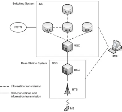
2.9. GSM network topology. . . 30
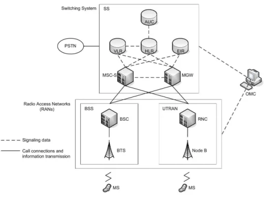
2.10. UMTS network topology. . . 33
2.11. UMTS and legacy GSM network topology. . . 34
2.12. UMTS and legacy GSM softswitch network topology. . . 35
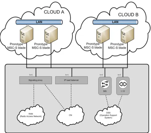
2.13. MSC-S Blade Cluster. Adapted from [66]. Note that the notation 1+1 means that the device is configured such that there is one primary device and at least one secondary device (to provide redundancy). . . 38
3.1. Ericsson MSC-S hybrid cluster topology. . . 42
3.2. Ericsson MSC-S external cluster topology. . . 43
3.3. Ericsson MSC-S split cluster topology. . . 44
4.1. Stockholm laboratory B network topology. . . 53
4.2. Canada laboratory network setup. . . 53
4.3. Average RTT between the Canada laboratory and the Stockholm laboratories. . . 54
4.4. Maximum RTT between the Canada laboratory and the Stockholm laboratories. . . 55
4.5. Average packet loss rate between the Canada laboratory and the Stockholm laboratories. . . 55
4.6. Ethernet over IP encapsulation example. . . 56
4.7. VPN encapsulation example. . . 57 xiii
4.8. Client to client bridging concept with the tunnels shown on the left and the logical view of the network shown on the right. . . 57 4.9. Network topology when testing the hybrid Ericsson MSC-S BC. . . 60 4.10. Stockholm laboratory B network topology when testing the external
Ericsson MSC-S BC. . . 63 4.11. Canada laboratory network topology when testing the external Ericsson
MSC-S BC. . . 66 4.12. Stockholm laboratory B network topology when testing the
geographi-cally split Ericsson MSC-S BC. . . 68 4.13. Canada laboratory network topology when testing the geographically
split Ericsson MSC-S BC. . . 71 4.14. Stockholm laboratory B network topology when testing the
geographi-cally split Ericsson MSC-S BC with the Canada laboratory. . . 72 5.1. TCP bandwidth between blades inside the provider’s network over a
period of 24 hours. . . 103 5.2. TCP throughput between blades inside the provider’s network histogram
and density function. . . 104 5.3. UDP bandwidth between blades inside the provider’s network over a
period of 24 hours. . . 104 5.4. UDP throughput between blades inside the provider’s network histogram
and density function. . . 105 5.5. Jitter between blades inside the provider’s network . . . 105 5.6. Jitter between blades inside the provider’s network histogram and
density function. . . 106 5.7. Packet loss between blades inside the provider’s network . . . 106 5.8. Packet loss between blades inside the provider’s network histogram and
density function. . . 107 5.9. Average RTT between blades inside the provider’s network . . . 107 5.10. Maximum RTT between blades inside the provider’s network . . . 108 5.11. TCP bandwidth between the provider and the Isolated machine in
Stockholm. . . 109 5.12. UDP bandwidth between the provider and the Isolated machine in
Stockholm. . . 109 5.13. TCP bandwidth between the provider and the Isolated machine
his-togram and density function. . . 110 5.14. UDP bandwidth between the provider and the Isolated machine
his-togram and density function. . . 110 5.15. Average RTT between the provider and the Isolated machine in Stockholm.111 5.16. Maximum RTT between the provider and the Isolated machine in
Stockholm. . . 112 5.17. Memory read latency for varying memory sizes (from 0 to 192 MB) . . . 113
1.1. Global Mobile Data Traffic Growth. Adapted from [10] . . . 2
3.1. Motivations to implement an Ericsson MSC-S BC in the Cloud . . . 45
3.2. Drawbacks to implement an Ericsson MSC-S BC in the Cloud . . . 46
4.1. HLR traffic generator machine’s features. . . 50
4.2. RAN traffic generator machine’s features. . . 50
4.3. Bridge machine’s features. . . . 51
4.4. Cloud machine’s features. . . . 51
4.5. Stockholm laboratory B machines’ features. . . 51
4.6. Canada machine’s features. . . . 52
4.7. Ericsson MSC-S BC network contraints. . . 58
4.8. Compilation of tests where a MSC-S blade was added to an existing Ericsson MSC-S BC with no network impairments between the cloned blade and the leader. . . 75
4.9. Compilation of tests where a MSC-S blade was removed from an existing Ericsson MSC-S BC. . . 77
4.10. Description of every step taken throughout the Ericsson MSC-S BC migration from the Stockholm laboratory B to the Stockholm laboratory A. . . 78
4.11. Description of every step taken throughout the Ericsson MSC-S BC migration from the Stockholm laboratory B to the Stockholm laboratory A. (cont.) . . . 79
4.12. Description of every step taken throughout the Ericsson MSC-S BC migration from the Stockholm laboratory A to the Stockholm laboratory B. . . 79
4.13. Description of every step taken throughout the Ericsson MSC-S BC migration from the Stockholm laboratory A to the Stockholm laboratory B. (cont.) . . . 80
5.1. Dhrystone benchmark results from Ubuntu GCC [75]. . . 102
5.2. Obtained results running Dhrystone Benchmark . . . 114 xv
B.1. Measurements compiled when an external Ericsson MSC-S BC cluster was serving traffic with different delays between the blades and the rest
of the system. . . 170
B.2. Measurements compiled when an external Ericsson MSC-S BC cluster was serving traffic with different packet loss rates between the blades and the rest of the system. . . 171
B.3. Measurements compiled when an external Ericsson MSC-S BC cluster was serving traffic with different combinations of delay and packet loss between the blades and the rest of the system. . . 172
B.4. Measurements compiled when an geographically split Ericsson MSC-S BC cluster was serving traffic with different delays between blade groups. 173 B.5. Measurements compiled when a geographically split Ericsson MSC-S BC cluster was serving traffic with different packet loss rates between the blades. . . 174
B.6. Measurements compiled when an Split Ericsson MSC-S BC cluster was serving traffic with different combinations of delay and packet loss between the blades and the rest of the system. . . 175
C.1. Cloud Service Providers’ features . . . 178
C.2. Cloud Service Providers’ features (cont.) . . . 179
C.3. GoGrid Cloud Servers options. Adapted from [80] . . . 180
C.4. GoGrid payment plans [81] . . . 181
C.5. Standard Dedicated Server features [82] . . . 181
C.6. Advanced Dedicated Server features [82] . . . 181
C.7. Ultra Dedicated Server features [82] . . . 181
C.8. GoGrid Outbound traffic billing [81] . . . 182
C.9. Rackspace servers . . . 183
C.10.Rackspace server pricing based in a Linux Server. Adapted from [88] . . 184
C.11.Rackspace bandwidth pricing based in a Linux Server [88] . . . 184
C.12.Savvis DL-series servers [94] . . . 188
C.13.Savvis BL-series servers [94] . . . 189
C.14.Savvis Open Cloud Compute Instances types [94] . . . 190
C.15.IBM Instances types [95] . . . 192
C.16.Amazon EC2 server instances [101] . . . 195
5.1. UDP script . . . 97
5.2. TCP script . . . 99
5.3. Ping script . . . 100
A.1. OpenVPN Server configuration file . . . 134
A.2. bridge-start.sh . . . 135
A.3. bridge-stop.sh . . . 136
A.4. OpenVPN Client configuration file . . . 137
A.5. Network configuration file . . . 139
A.6. 70-persistent-net configuration file . . . 140
A.7. qemu-ifup script . . . 142
A.8. qemu-ifdown script . . . 142
A.9. network_bladeX_vpn configuration file . . . 146
A.10.network_bladeX_dual configuration file . . . 148
A.11.config_bladeX_vpn configuration file . . . 150
D.1. Awk parser to gather information from UDP test’s output. . . 199
D.2. Awk parser to gather information from TCP test’s output. . . 200
D.3. Awk parser to gather information about the average RTT. . . 200
D.4. Awk parser to gather information about packet loss. . . 201
D.5. Awk parser to gather information about the maximum RTT. . . 201
D.6. Awk parser to gather information about the minimum RTT. . . 202
D.7. Awk parser to gather information about jitter value. . . 202
3GPP Third Generation Partnership Project API Application Programming Interface APG Adjunct Processor Group
ARP Address Resolution Protocol AUC Authentication Center
BGCF Breakout Gateway Control Function BGP Border Gateway Protocol
BSC Base Station Controller BSS Base Station System BTS Base Transceiver Station
BW Bandwidth
CAPEX Capital Expenditure CPU Central Processing Unit
CS Circuit-Switched
CSCF Call Session Control Function
CSMA/CD Carrier Sense Multiple Access with Collision Detection DEC Digital Equipment Corporation
DoS Denial of Service
EDGE Enhaced Data rates for GSM Evolution EIR Equipment Identity Register
eNB Evolved Node B
EoIP Ethernet over IP
EPC Evolve Packet Core
ETSI European Telecommunications Standard Institute
GB Gigabyte
Gbps Gigabits per second
GHz Gigahertz
GPRS General Packet Radio Service
GSM Global System for Mobile communications GUI Graphical User Interface
HLR Home Location Register HSS Home Subscriber Server IaaS Infrastructure as a Service
IDE Integration Development Environment
IEEE Institute of Electrical and Electronic Engineers IETF Internet Engineering Task Force
IGMP Internet Group Management Protocol IMEI International Mobile Equipment Identities IMS IP Multimedia Subsystem
IMSI International Mobile Subscriber Identity
I/O Input/Output
IP Internet Protocol
ISO International Standard Organization IT Information Technology
KVM Kernel-based Virtual Machine
LAN Local Area Network
LTE Long Term Evolution
MAC Media Access Control
MB Megabyte
Mbps Megabits per second
MGCF Media Gateway Control Function
MGW Media Gateway
MIPS Million Instructions Per Second MME Mobility Management Entity MPLS Multi-Protocol Label Switching MRF Media Resource Controller
ms millisecond
MSC Mobile services Switching Center MSC-S Mobile Switching Center Server MSC-S BC MSC-S Blade Cluster
MSISDN Mobile Station Integrated Services Digital Network MTBF Mean Time Between Failures
MTTR Mean Time To Repair
MTU Maximum Transmission Unit NAT Network Address Translation NGN Next Generation Network
NIST National Institute of Standards and Technology NMC Network Management Center
NMS Network Management Subsystem NSS Network Switching Subsystem OMC Operation and Maintenance Center OPEX Operational Expenditure
OS Operating System
OSPF Open Shortest Path First OSS Operation Support System PaaS Platform as a Service
PC Personal Computer
PCP Priority Code Point
PDN GW Packet Data Network Gateway PIM Protocol Independent Multicast
PS Packet-Switched
PSTN Public Switched Telephone Network QoE Quality of Experience
QoS Quality of Service
RAM Random Access Memory
RAN Radio Access Network
RIP Routing Information Protocol
RFC Request For Comments
RNC Radio Network Controller
RTT Round-Trip Time
SaaS Software as a Service
SAE System Architecture Evolution SBC Session Border Controller
SCTP Stream Control Transmission Protocol
SGW Serving Gateway
SIM Subscriber Identity Module SIP Session Initiation Protocol SIS Site Infrastructure Support SLA Service Level Agreement SMS Short Message Service
SPX Signaling Proxy
SS Switching System
SSH Secure Shell
TCP Transmission Control Protocol TDM Time-Division Multiplexing TLB Translation Lookaside Buffer UDP User Datagram Protocol UPS Uninterruptible Power Supply
UMTS Universal Mobile Telecommunications System UTRAN UMTS Radio Access Network
VAX Virtual Address Extension VLAN Virtual Local Area Network VLR Visitor Location Register
VM Virtual Machine
Introduction
The aim of this chapter is to describe the thesis project and the organization of the thesis itself. First, an overview of the subject is provided so that the reader can grasp the context of the study and completely understand the rest of the thesis. After that, the problems addressed in this project are described, followed by a statement of the goals and the purpose of the project. Next, the methodology that was adopted to solve the problems previously posed is described. Thereafter, the target audience of this thesis is presented, and the scope and limitations of the project are clearly stated. Finally, an outline of the thesis itself is presented to highlight the structure of the thesis in order to make it easier for the reader to utilize this thesis.
1.1.
Overview
Nowadays, services such as telephony, Internet access, and Short Message Service (SMS) in mobile terminals are increasingly expected by end users to have the same Quality of Experience (QoE) as the user obtains when using wired devices [1]. However, the amount of resources necessary to provide such large scale services increases with the demands upon the service, and the capital expenditure (CAPEX) required to build and sustain such a deployment is becoming a major concern for telecommunication operators [2]. Furthermore, demands in terms of bandwidth are increasing, especially due to the emergence of new services and applications requiring Internet access [3], as it can be seen in Table 1.1. Therefore, an important research challenge is to develop new solutions so that the initial expenses are reduced and, at the same time, future needs can be met easily and without extensive modifications when scaling up resources. Currently, solutions to boost mobile networks’ bandwidth are being addressed by the Long Term Evolution/Evolved Packet Core architecture (LTE/EPC) [4] [5]. LTE introduces sophisticated radio-communication techniques, enabling faster and more efficient access networks, while EPC involves the deployment of a packet-based core network capable of dealing with future traffic increases [6]. Additionally, the IP Multimedia Subsystem (IMS) [7] [8]
[9] is the main framework to provide voice and SMS services over IP.
Table 1.1. Global Mobile Data Traffic Growth. Adapted from [10]
Year Annual Increment
2008 156%
2009 140%
2010 159%
2011 (expected) 131% 2012 (expected) 113%
The National Institute of Standards and Technology (NIST) [11] defines Cloud computing as "a model for enabling ubiquitous, convenient, on-demand network access to a shared pool of configurable computing resources (e.g., networks, servers, storage, applications, and services) that can be rapidly provisioned and released with minimal management effort or service provider interaction".
Cloud computing is an emerging industry with the active participation of many companies, including many telecommunication operators as illustrated by Figure 1.1. The set of services being offered by these companies is also becoming broader, thus reaching and satisfying a more diverse range of customer requirements – enabling these customers to outsource their IT operations [12]. Data warehousing, computing as a service, and virtual data centers are just a few examples of cloud services. At the same time, exploiting cloud computing enables customers to save hardware acquisition and network deployment costs. This thesis considers how to provide telecommunication services through cloud-based solutions. We are not the first to consider this idea, as it has already been pondered by Caryer et al. [13], who suggested the utilization of cloud computing resources to support the development of Next Generation Networks (NGN).
What remains to be seen is whether current cloud services meet the Quality of Service (QoS) requirements for implementing applications such as a Mobile Switching Centre Server (MSC-S), Home Location Register (HLR), or any other application on which mobile services are dependent. Our study has focused on a practical demonstration of whether a cloud-based implementation is possible for an MSC-S application, considering the difficulties that such a deployment entails, and on evaluating the results obtained. It is important to note that telecommunication services demand a QoS that is considered to be difficult to achieve in a normal environment, but despite this, cloud technology needs to be able to deliver the required QoS. Additionally, all the drawbacks that use of the public Internet may introduce when providing a service through it must be kept in mind (Oredope and Liotta also regarded this as an important concern in [14]). However, other issues also need to be addressed in our investigation. For instance,
Figure 1.1. Cloud computing companies
as it is mentioned in [15], interoperability among different cloud environments could be a concern, and tests should be performed to examine this possible complication.
1.2.
Problem description
The main problems this thesis project deals with (and to which a solution is provided) are:
• Telecommunication applications generally have a weakness due to central-ization deployment: These applications are commonly run on specialized hardware components, and these components are normally deployed together in racks. This implies the existence of a single point of failure if something harmful occurs in the facilities where these racks are placed. In addition, these centralised implementations limit services’ scalability, and the specific geographic location of these servers leads to delay constraints upon some services.
• Large CAPEX and high risk in deploying a telecommunication network: The design and implementation of telecommunication networks entail large initial investments, which have become the main difficulty for new telecommunication operators - creating a high barrier to entry that favors incumbents.
Additionally, the level of risk associated with such a venture is very high for investors.
• Uncertainty of the suitablity of migrating telecommunication applications to the Cloud: We consider a solution where Cloud computing is used to address the problems stated above, as suggested by Caryer, et al. [13]. However, as of the time this thesis project was proposed in August 2011, Cloud environments had not yet been tested against the constraints that these applications require in terms of QoS, therefore thorough testing needed to be carried out to prove that a cloud based solution is actually suitable.
1.3.
Goals
The main goals of this master thesis project are:
• Practically demonstrate that an Ericsson MSC-S Blade Cluster (MSC-S BC) can be implemented deploying prototype MSC-S blades with limited functionality in a current cloud computing environment. Carry out tests to observe whether this solution may have performance problems from the network perspective, especially in light of the QoS requirements imposed by telecommunication services.
• Extend the first goal to the case where the prototype MSC-S blades that form the Ericsson MSC-S BC are geographically distributed. Conduct tests to demonstrate that the performance of the implementation meets the application’s QoS requirements.
In order to ease our task and to efficiently achieve our main goals we divided the work into several tasks. The tasks on which we focused are:
• Design a completely functional network environment so that the prototype MSC-S blades can be run on standard x86-based computers while meeting the application’s requirements (we consider the environment’s network configura-tion and limitaconfigura-tions during this design process). After the configuraconfigura-tion of the network and computer environment, we deployed the application prototype in order to test that it operates correctly (from a functional point of view). After ensuring that it operates correctly we will conduct performance testing to ensure that the solution meets all of the performance requirements, i.e., that the solution is suitable for our purposes.
• Utilize the previous solution in a test bed to simulate a cloud within the Ericsson network, so that the MSC-S application prototype can be tested in the presence of impairments that might be introduced by a real Cloud
environment. These impairments were simulated by adding Cloud network penalties such as delay and packet loss. In addition, a vitualization layer was added over the native machine on which the application was run.
• Conduct a survey to evaluate current Cloud computing providers in the market to see which can meet our requirements in terms of computing capacity and network capabilities, while preparing for our last step: testing the application in a real Cloud environment.
• Verify that it is possible to exploit available commercial Cloud computing resources to host the MSC-S application prototype by performing thorough tests in a selected provider’s Cloud.
1.4.
Purpose
The purpose of this thesis is to describe the design, implementation, and evaluation of a network solution for the Ericsson MSC-S BC so that the problems stated in Section 1.3 can be solved using current commercially available Cloud computing services. Success in such a task would provide a firm foundation for future telecommunication network application deployments in a Cloud. Addition-ally, the testing will address important issues regarding this solution. Since Cloud services provide very simple billing schemes, the initial expenses needed to build a modern telecommunication network would be reduced substantially. In addition, the distributed resources that could be utilized via Cloud computing could increase redundancy in the network, potentially preventing major service disruptions from ocurring due to many different types of failures. Finally, a satisfactory Cloud solution for this sort of applications would introduce an inflexion point in the design and deployment of modern telecommunications networks and would certainly lead to further investigations concerning the migration of other telecommunication services and applications to a Cloud environment.
Furthermore, this thesis provides a thorough analysis of current main Cloud computing providers. The analysis focuses on the constraints of the Ericsson MSC-S BC application, such as the required computing performance (in terms of bounded service times), bandwidth, security, Service Level Agreements (SLAs), and appropiate access to the Could resources in order to have full control of the machines’ configuration. This survey provides useful insights into which Cloud providers are suitable to host telecommunication services requiring high QoS.
1.5.
Methodology
In order to fulfill the goals of this master’s thesis project, both qualitative and quantitative approaches were utilized. Secondary research was used as a qualitative
method, starting with a literature review. Since previous studies may have already considered Cloud computing as a solution to implement telecommunication services for mobile networks we began by seeking out existing solutions. Moreover, this review provided material for our background chapter and allowed us to obtain a full state-of-the-art overview of the subject. This literature review also provided a solid foundation upon which we could base our ideas.
In addition, another qualitative method was our survey. The purpose of this survey was to evaluate the current Cloud computing providers and analyze whether any of the offerings were suitable for our task. The first part of this survey, a thorough secondary search, was conducted to narrow down the number of Cloud provider candidates based on their websites and information in their white papers. We eliminate from further consideration any providers that did not meet our basic technical requirements. Secondly, personal enquiries were posed to the first providers to respond, enabling us to clarify our understanding of their offerings. These personal queries were conducted by e-mail and phone conversations. Finally, a final decision to select a single Cloud provider for testing was made based on all the data obtained from the survey and personal enquiries. In Chapter 5, a more detailed explanation of the survey process is provided.
Based upon the literature study, and the requirements of our employer, a set of test cases were developed to guide the design and implementation of our solution to the problems described in Section 1.2 for the Ericsson MSC-S BC. Those experiments enable us to quantify the performance of our solution and to compare this performance to our employer’s QoS requirements for the telecommunications network application that was selected for our testing. Additionally, the Cloud provider selected as a potential test bed from the survey was evaluated on the basic requirements of the Ericsson MSC-S BC application. The measurements were conducted over a range of representative network parameters, computing capacity and memory latency.
1.6.
Scope
The project’s aim was to look for a stable solution, perform an analysis of the solution’s performance, detect the hindrances that could appear from a network perspective, and overcome them when possible. Therefore, a comparison of the performance of other solutions is outside the scope of this project.
In addition, some issues that we detected, which had nothing to do with the network aspects of the implementation, could not be resolved due to the complexity of the Ericsson MSC-S BC system. Solving these issues was out of the scope of this project, which was focused on the network aspects of the implementation, and required more complete knowledge of the system.
Finally, the technical implementation decisions made for our solution are explicitly stated and further explained below:
• The practical experiment was carried out using a Ericsson proprietary MSC application prototype with limited functionality. In the future, further studies should be conducted to verify the correct behaviour of a completely functional Ericsson MSC-S BC application, as well as other (related) applications to see if the results of this study can be generalized to other (similar) applications. • A Linux environment was used to run the application, as Linux was the
target execution environment for both the virtual machines in the Cloud and the application’s current host operating system. Ubuntu 10.04 LTS was the selected distribution due to its stability, ease of use, and our familiarity with it. While this was not the same Linux distribution used by the application in its commercial deployment (OpenSUSE), the performance differences between Linux implementations were not considered to be a significant issue.
• The tests were realized on a simulated Cloud in a laboratory environment and on a single Cloud provider’s real Cloud environment. Comparison with other Cloud implementations is left as future work, but we expect different environments to give comparable results (after compensating fot the difference in configurations - such as processor speed, available memory, disk throughput, network bandwidth, etc.).
• Only two network tunneling implementations were considered in the experiments: Virtual Private Network (VPN) and Ethernet over IP (EtherIP), as the purpose of this project was not to evaluate all the options but to implement a solution that was functional.
• Kernel-based Virtual Machine (KVM) and VMware were the only virtual-ization hypervisors used in the project. These two hypervisors were used to simulate a real Cloud virtualization environment, and they were considered sufficient for our purposes. We were not concerned with the small difference in performance of different virtualization methods, since we were not looking for small differences, but rather want to see if the proposed solution could meet the basic QoS requirements.
• A specific set of measurement tools were selected to collect the desired performance data. The selection of these tools together with our test results and analysis are presented in Chapter 4.
1.7.
Limitations
The first of the limitations we faced was our lack of background knowledge regarding the solution we were expected to implement. As far as we knew, there
had not been another investigation with a similar purpose as ours, although the idea was suggested in a general manner by Caryer, et al. [13].
Moreover, we suffered several setbacks in our efforts to deploy the simulated Cloud within Ericsson’s internal network. These complications were associated with security and privacy policies that, at first, prevented us from freely configuring the environment. Additionally, when we contracted for service from a commercial Cloud service provider, we had some problems communicating with this Cloud provider’s machines with the Secure Shell (SSH) protocol, as SSH was filtered out by the gateway of the Ericsson network. However, these issues were quickly resolved by our project supervisor and our manager.
The last step of the project, which consisted of testing the Ericsson MSC-S in a real cloud environment was not fully accomplished due to Ericsson’s privacy policies. Permission to upload the application to such external location was not granted, and therefore this last step was limited to a thorough bench-marking process – with the goal of demonstrating theoretically that the system would operate correctly in such environment.
1.8.
Target audience
Researchers and telecommunication operators interested in Cloud computing’s potential uses within the telecommunication services market are the main targets of this thesis, specially, those who are concerned about the network performance of this sort of solution. In addition to these readers, any person interested in acquiring knowledge about the testing environment used in this research project can take advantage of this thesis as additional documentation about how to realize such a test environment and how to conduct performance measurements.
1.9.
Thesis outline
The thesis is structured in a linear manner, where earlier chapters provide a general overview of the subjects necessary to understand the remainder of the thesis. It is strongly recommended that the reader study the theoretical background to provide an appropiate context for the subsequent experimental work.
Chapter 1 provides a general introduction to the thesis. While Chapter 2 provides general background information. Chapter 3 describes how the Ericsson MSC-S BC prototype could be run in a Cloud environmnent, while Chapter 4 describes tests of it in a laboratory emulated Cloud environment. Chapter 5 describes the survey of Cloud service providers and the results of our survey and bench marking. Chapter 6 presents our conclusions and suggest future work.
Appendix A is a manual for use by others who might want to configure a laboratory Cloud environment and run the tests tools that we have used. Appendix B includes the tables that contain the samples taken in Chapter 4. Appendix C contains the details of the Cloud services prover survey. Finally, Appendix D presents the scripts that were used for the bench-marking processes conducted in this project.
General background
The purpose of this chapter is to give a brief overview of the technologies and concepts involved in this thesis so that the reader can easily read the rest of the thesis and understand why and how the work has been done. In addition, the information provided here focuses on the essential ideas that are directly related to this project, without going into unnecessary details.
Since the purpose of this thesis project is to analyze whether telecommunication services, specifically mobile networks’ applications, can be migrated to the Cloud in practice from a network perspective, a short summary of IP networking is provided in Section 2.1, followed by an overview of the two main technologies that are relevant to the project: Cloud Computing (Section 2.2) and mobile network architectures (Section 2.3). Finally, a brief theoretical description of the Ericsson MSC-S BC prototype is provided in Section 2.4, since this was the platform on which the first tests were performed.
2.1.
Networking
This section presents and describes the networking concepts necessary to undertand this thesis. Initially, a brief explanation of the layering concept characteristic of many network architectures is provided. Following this, each protocol that will be relevant to this thesis is described. The order that we will follow is from the bottom to the top of the protocol stack.
2.1.1. Network Layering concept
A computer network consists of several computers interconnected with each other via a network. Different models of network stacks exist nowadays, but the models that are most widely used are: the Open Systems Interconnection (OSI) model and the TCP/IP model. The TCP/IP model is based on the Transmission Control Protocol (TCP) and the Internet Protocol (IP) family of protocols. Both
of these models are based on the concept of protocol layers [16]. According to this concept each layer is responsible for some functions in the communication process, thus reducing the complexity of the total protocol by isolating information that is not relevant to other layers within a layer. This layered architecture makes it easy to adapt the network model as new technologies evolve, since in principle each layer can be modified independently of the others – as long as it continues to provide the same services to the higher layer and to require the same services from the lower layer. Each layer offers a set of services to its immediate upper layer, while the latter relies on the services provided by the former when realizing its own functions. When sending data, the user generally passess user data through all those layers, from the application layer on the top to physical layer in the sender and back up the stack at the receiver.
The TCP/IP model is a modification of the OSI model. The TCP/IP model is the basis of the Internet [17]. The TCP/IP network model specifies the set of rules and protocols that are necessary to communicate among hosts within a TCP/IP network. These rules define how data should be sent in terms of forming IP packets, addressing these packets to their destination, routing packets, and forwarding these packets to the correct destination [18]. The TCP/IP model has four layers, while OSI model has seven layers, as we can see in Figure 2.1. Although they differ from each other, they are very similar from the transport layer down to the physical layer.
2.1.2. Network Access layer
There are several network access layer protocols available. For example, Ethernet is the dominant local area network (LAN) technology and has been defined in various standards developed by the IEEE 802.3 working group [20]. The initial version of Ethernet used a physical shared media (a coaxial cable), hence there was a need for a media access control protocol to decide when a host could transmit a frame, how long it should wait before transmitting, and when it should re-transmit. Subsequently the Ethernet standard was broadened to include many different types of media. Increasingly Ethernet is implemented by connecting each individual host to a switch. An example of switched Ethernet network can be seen in Figure 2.2 (A).
The main elements of which the Ethernet technology is composed are the access protocol, the hardware components, and the Ethernet frame structure. When data (and potentially also a logical link layer header) reaches the Ethernet layer it is encapsulated in Ethernet frames that are forwarded across the network to its destination. The Ethernet access method is called Carrier Sense Multiple Access with Collision Detection (CSMA/CD). This access method provides a way of sharing the medium so that all the hosts in the network can transmit data to each other
Figure 2.1. Comparison of OSI and TCP/IP models. Adapted from figure 1 of [19].
without monopolizing all the resources. However, in a switched Ethernet there is no reason to use the CSMA/CD protocol, hence later versions of the IEEE 802.3 standards define different media access and control protocols, for example, allowing full duplex communication and allowing elimination of inter-frame gaps. Finally, the hardware includes the cables, connectors, and electronic circuitry that allows the transfer of data in a LAN using Ethernet technology.
Furthermore, for other than point-to-point communication an addressing method is necessary so that the destination can know that a given frame is potentially for it and in some cases so that the receiver can know to whom a reply should be set. In the case of Ethernet we use a Media Access Control (MAC) address, which consists of a forty-eight-bit number. There are two main types of MAC addresses: unicast and multicast (which includes link layer broadcast). Additionally one bit of the MAC address indicates whether this address is globally unique or not. At the time of manufacturing an Ethernet interface the vendor assigns a unique address to each of their network interfaces. In order to assign globally unique MAC addresses the vendors buy blocks of 224addresses from the IEEE. In the case of Internet Protocol version 4 (IPv4) a translation from IP address to MAC address is possible using the Address Resolution Protocol (ARP). Details of the operation of ARP can be found in [21].
Figure 2.2. A switched Ethernet network topology (A) and the logically equivalent LAN representation (B).
In summary, today Ethernet refers to both the hardware and software that realizes the most common implementation of the lowest level communication layer and it delivers frames of bits between machines in an Ethernet network. Ethernet is the most common first layer of the TCP/IP model, thus any protocol built on top relies on the services provided by Ethernet to provide their own services.
2.1.3. Virtual Local Area Network (VLAN)
A Virtual Local Area Network (VLAN) [22][23][24] is composed by a group of hosts that communicate with each other as if they were in the same broadcast domain (a subnetwork) without nesessarily being in the same physical location, hence they forming a virtual subnetwork on top of the physical network. A VLAN has the same properties as a physical LAN, although VLAN membership configuration is implemented by software instead of reallocating physical devices and connections as would be required for physical LANs.
Additionally, if several VLANs share a physical connection, it is important to remember that the bandwidth is shared by all the Virtual LANs. VLANs are set up by tagging the traffic for each VLAN (for example using IEEE 802.1Q tags), by adding a tag field to the Ethernet control header, and by configuring layer 2 switch ports [25]. An example of the virtualization provided by this technology is illustrated in Figure 2.3. Note that it is also possible to use the IEEE 802.3Q three bit Priority Code Point (PCP) field to specify priorities, hence the different VLANs need not equally shared the bandwidth.
Figure 2.3. Deployment of two VLANs (1 and 2) over a physical LAN.
2.1.4. Internet Protocol (IP) layer
IP is the core technology upon which the global IP network, more commonly known as "The Internet", is based. As Request For Comments (RFC) 791 points out, IP is a protocol whose purpose is "to provide for transmitting blocks of data called datagrams from sources to destinations, where sources and destinations are hosts identified by fixed length addresses" [26]. IP is commonly considered to be a best-effort protocol, which means that it does not guaranteed that the datagrams reach their destinations.
The only IP concept we are going to detail is routing, is how IP packets reach their target. Routers are intermediate devices that forward datagrams to their correct destinations using the information provided in the IP header of the packet and the routing information which the router has. Each router keeps a routing table and makes forwarding decisions based on entries in this table. Routing tables can be manually configured, which normally only occurs in small networks, or dynamically configured by routing protocols when dealing with a large number of routes. Some well-known examples of routing protocols are Open Shortest Path First (OSPF), Routing Information Protocol (RIP), and Border Gateway Protocol (BGP). IP routes are commonly specified for blocks of IP addresses (subnets), which reduces the size of the routing table (as opposed to having to keep an entry for each possible destination IP address). The specific route determines the output interface to which a given IP datagram should be forwarded on. A route specification consists of the destinations that can be reached by the route and the next hop on this path (this is generally stored as a three tuple: destination IP address. network mask, and outgoing interface - but the table may also include weights, maximum segment size, maximum transport unit size, etc.). An example IP network is illustrated in
Figure 2.4, where the routing table for router 2 is represented.
Figure 2.4. IP network example. The routing table presented contains both single and multidestination routes.
In addition to globally routable IP addresses, there are blocks of IP addresses used only for private purposes, thus IP packets to these destination addresses are never forwarded to the global Internet; hence these addresses can be utilized repeatedly within separate private IP networks. These IP addresses are referred to as private IP addresses, while the globally routable Internet addresses are referred to as public IP addresses. Therefore, these private IP addresses are commonly used for internal company networks, testing environments, or any other network that is isolated from the Internet. However, Internet access can be provided to hosts that utilize a private IP address by introducing a gateway, such as a Network Address Translation (NAT). Packets arriving at the NAT can have a public destination address (hence they may be forwarded to the internet) or they may have a private destination IP address in which case they can only be forwarded within the private network. Note that in all cases before forwarding a packet with a private IP
source address the NAT must replace this source address with one of its own source addresses (and perhaps modify the transport protocol source port number - so that it can return a response packet to the correct internation host’s interface). A NAT that is connected to the global internet must of course replace a private IP source address with one of its own public IP addresses.
The Internet Protocol is more complex than presented here, and many of its characteristics have been omitted in this brief summary. However, a thorough explanation of IP can be found in any networking textbook, such as [18].
2.1.5. Transport layer
The transport layer provides an end-to-end communication protocol for use by applications. Application layer protocols can be built on top of a transport layer protocol. There are several commonly used transport protocols in the Internet, each offers a set of features that are suitable for different types of applications. Some of these features are: connection orientation or connectionless, flow control, congestion avoidance, reliability, in-order delivery, security, multiple streams, multi-homing, and byte or message oriented transmission. The transport protocols that have had an important role in our work are TCP, UDP, and SCTP. Each of these protocols is explained in more detail below [27] [28].
2.1.5.1 Transmission Control Protocol (TCP)
TCP is described by in RFC 793 [29] as a protocol for delivering bytes with a high reliability between hosts over an IP network. TCP’s primary purpose is to provide a trustworthy, accessible logical connection between pairs of processes. The main characteristics of the protocol are that provides a connection orientation, bidirectional, byte-stream with in-order delivery and reliability. This reliability is provided through a variety of retransmission schemes. Additionally, flow and congestion control mechanisms are implemented so that neither the receiver nor the network becomes overloaded.
2.1.5.2 User Datagram Protocol (UDP)
The aim of UDP [30] is to make possible a datagram mode of packet-switched communication via an IP network. UDP offers a procedure to send data between applications with minimal protocol overhead. Its main traits are its connectionless orientation and unreliability, which implies that neither delivery nor duplicate prevention are guaranteed. Therefore, applications that require in-order packet delivery should not use UDP or they must build their own mechanism on top of UDP. However, the reduced overhead of UDP and its simplicity make it ideal for real-time applications.
2.1.5.3 Stream Control Transmission Protocol (SCTP)
SCTP was designed to transport Public Switched Telephone Network (PSTN) signaling messages through IP networks [31] [32]. However, SCTP has become a general purpose Internet Engineering Task Force (IETF) transport protocol. As with TCP, SCTP provides a reliable, connection oriented, bidirectional service with flow and congestion control mechanisms. Nevertheless, there are some differences [33]:
• SCTP uses a four-way handshake during session establishment to prevent the Denial of Service (DoS) attacks to which TCP is subject [34].
• SCTP implements message-based data transfer using a fragmentation and reassembly scheme.
• SCTP supports out-of-ordered data delivery in addition to the in-order delivery.
• A multihoming feature is offered to allow binding a single SCTP association to several IP addresses, providing redundancy and increased fault-tolerance. • The level of reliability can be reduced by specifying a lifetime for the messages. • An SCTP association can include multiple individual streams, each one with its own delivery ordering scheme, thus preventing head-of-line blocking [35].
2.1.6. Application layer
The application layer consists of programs that utilize the lower layers to communicate. It is important to note the importance the lower layers have for applications, as each one in turn provides an abstraction of all the layers below it. Therefore, any application can communicate with its counterpart via the Internet by utilizing the TCP/IP stack. Depending on the transport layer protocol selected, the transport could be reliable (for example, when using TCP or SCTP) or unreliable (when using UDP), thus the application designer will need to think about what level of reliability the application requires when selecting which transport protocol to use.
Furthermore, application software may directly be used by an end user or used to provide further functionalities to other applications built on top of this application layer protocol. Hence, many applications can isolate functions into a logical sub-layer, enabling easier later modifications while minimizing complexity.
2.1.7. Unicast, Multicast, and Broadcast
An additional functionality of IP is that a datagram can be sent to many recipients at the same time without the source needing to replicate the transmission for all these destinations. In such a "multicast" (or broadcast) the sender transmits a single packet and the network is responsible for replicating this packet as necessary to deliver it to all the targets. Today the majority of packets that traverse the wider Internet are sent to a single destination. This is called unicast transmission. When more than one receiver is involved we can distinguish between two varieties: multicast and broadcast. If the packet is going to be forwarded to all hosts in the network, then it would be broadcast. It should be noted that due to the effects of such a broadcast packet many networks filter out such packets and do not forward them beyond a certain boundary (for example a subnet or network). On the other hand, if this packet is to be delivered to a specific group of receivers, then the packet would be multicast. Since multicast has been used within our tests we will give a more detailed explanation of this type of traffic below.
In order to support multicast traffic [36] some protocols must be supported and multicast enabled routers must be present in the network. The Internet Group Management Protocol (IGMP) handles group memberships indicating which hosts want to listen to a given multicast address. This indication is sent via IGMP to the adjacent multicast-routers [37]. The Protocol Independent Multicast (PIM) protocol allows communication among multicast-routers so that a multicast packet can reach distant participants [38]. Every multicast packet has a multicast destination IP address, which is in the range of 224.0.0.0 and 239.255.255.255.
Basically, a multicast communication process consists of several steps: all hosts that wish to listen to a specific multicast destination IP address register using IGMP with its adjacent multicast-router identifying the multicast destination IP address that they want to listen to. The multicast router forwards the interest in a specific multicast destination IP address until a path is created from the source to the destination. Now multicast datagrams can traverse the network to the interested receiver(s). Finally, if a listener wants to leave the multicast group it notifies its adjacent multicast-router and the path will be eliminated when there is no one else connected to this multicast-router that is interested in this multicast destination address. An example of a tree created for a multicast communication can be seen in Figure 2.5.
Figure 2.5. An example of a multicast tree.
2.1.8. Tunneling
The concept of tunneling is used when a level of virtualization over an underlying network (such as the Internet) is required in order to connect two or more networks (as if they were directly connected). An example is shown in Figure 2.6. There are many types of tunnel implementations. The choice of tunneling method depends on the network layer over which the tunnel will be set up and on requirements, such as the desired security. A tunnel encapsulates data units of the layer that is intended to be tunneled at one end of the tunnel and delivers them to the other end of the tunnel. At the receiver the encapsulated data units are decapsulated and the data is forwarded as ususal to its destination [39].
When tunneling Ethernet frames over IP [40], as was used in this project, the virtualization provides a virtual link layer connecting the involved networks. Therefore, any Ethernet frame that is sent in one network can go through the tunnel and reach the other end, as if both sites were directly connected to the same LAN. Note that the tunnel does not forward frames that do not need to be forwarded to the other site(s), hence Ethernet over IP (EoIP) acts as if the interconnecting tunnel is a distributed bridge.
Figure 2.6. Tunneling can be used to virtualize the network connected PC-1 .. PC-6.
2.2.
An approach to Cloud Computing
As stated in Section 1.1, Cloud computing can be realized in many different ways, which has caused its lengthwise and crosswise growth in the last years. However, every Cloud has some basic properties. This section summarizes the main characteristics of Cloud computing, then describes the different services and deployments that are found using this technology.
2.2.1. Cloud Computing features
The main features of Cloud Computing are on-demand provisioning, location independent resource pooling, Internet access, elasticity, network monitoring and metering, and outsourced maintenance [11][41][42][43][44]. Below we describe each of these in more detail.
2.2.1.1 On-demand provisioning
In any Cloud the computing resources are commonly ordered and accessed in an on-demand basis through the Internet (or in some cases through an intranet). This capability enables the customer to acquire whatever resources are desired whenever desired with almost complete independence, as if the resources were endless. To ease
this process, the Cloud capacity is normally managed through a provider’s specific Application Programming Interface (API). In many cases, the Cloud provider offers a very intuitive Graphical User Interface (GUI), such as the one shown in Figure 2.7. Using this GUI a customer simply specifies what is needed by typing and clicking on the interface, then the requested resources will be made available within a short amount of time. The freedom in terms of configuration depends on what level of virtualization the service offers, becoming more restrictive as the service goes up the logical ladder of services (from Infrastructure as a Service (IaaS) to Platform as a Service (PaaS) to Software as a Service (SaaS)). For further description see Section 2.2.7 and [43].
Figure 2.7. Rackspace GUI [45]
2.2.1.2 Location independent resource pooling
Processing power, storage, and generally any computing resource are physically located within the Cloud owner’s facilities, better known as data centers. The service provider is responsible for managing the available resources to serve multiple consumers at the same time, dynamically allocating and reallocating resources to these customers in an efficient manner depending on the customer’s current needs. This dynamic allocation is performed by means of Cloud computing management software, such as Eucalyptus [46] or Open Nebula [47], which enhances the effectiveness of the resources and the elasticity of what resources can be provided at any given time.
![Figure 2.1. Comparison of OSI and TCP/IP models. Adapted from figure 1 of [19].](https://thumb-eu.123doks.com/thumbv2/5dokorg/5511331.143615/40.892.293.602.185.535/figure-comparison-osi-tcp-ip-models-adapted-figure.webp)


![Figure 2.13. MSC-S Blade Cluster. Adapted from [66]. Note that the notation 1+1 means that the device is configured such that there is one primary device and at least one secondary device (to provide redundancy).](https://thumb-eu.123doks.com/thumbv2/5dokorg/5511331.143615/65.892.188.703.612.982/figure-cluster-adapted-notation-configured-primary-secondary-redundancy.webp)