How to Incorporate Security
Requirements
into the ArchWiz Tool
Caroline Uppsäll cul05001@student.mdh.se
2010-01-26
Master Thesis, Computer Science, 30 credits Supervisors:
Mälardalens University ABB Corporate Research: School of Innovation, Design and Engineering (IDT) Pia Stoll, pia.stoll@se.abb.com
Performed at: Mälardalens University:
ABB Corporate Research Rikard Land, rikard.land@mdh.se Västerås, Sweden
Abstract
This thesis have two tasks: one is to help in the development of the ArchWiz tool at ABB and the other is to find a way of how to formalise security related architectural responsibilities in a general way so that they can be incorporated in the tool. This thesis report focuses on the software quality attribute security.The ArchWiz tool is developed at ABB Corporate Research in Västerås. The scope of the tool is to serve as a software architecture guidance and knowledge tool for all software architecture
professionals within ABB. The ArchWiz tool is a way of helping the architects of ABB to match their product requirements with a list of general reusable requirements. The matched product requirements can then use the reusable requirement's architectural solutions, which are also presented in the tool. The tool focuses on usability, security and safety in this first version but it is constructed so that the user can add their own general requirements regarding any quality.
The architecture design phase in the development of a software system is a key part in the
development process, it gives the first design decisions and gives information on if the system will have potential to meet its key requirements. Security is a software quality that has grown in
importance for the architectural design of the system. There exist a number of potential threats and attacks that might breach the security of the software and these threats needs to be protected against. The ArchWiz project closed in December 2009 and at that time the tool was not finished. A good foundation and a GUI framework for further implementations were developed but to get a fully functioning tool more implementations need to be made. Security is one of the quality attributes, which the ArchWiz is supposed to support. Suggestions on how to formalise security
responsibilities in the tool have in this thesis been created and analysed. However, the suggestions need to be in incorporated in the tool and tested through users tests with the ABB architects. With the user tests as basis, the best suggestion can be selected.
Sammanfattning
Detta examensarbete innefattar två olika uppgifter: en är att hjälpa till med utvecklingen avverktyget ArchWiz på ABB, och den andra är att hitta ett generellt sätta att formalisera säkerhet på, så att det kan införlivas i verktyget. Denna rapport fokuserar på säkerhetskraven i mjukvarusystem. ArchWiz är ett verktyg utvecklat på ABB Corporate Research i Västerås. Syftet med verktyget är att fungera som guidning till mjukvaruarkitetkter och att vara ett kunskapsverktyg för alla som jobbar med arkitektur på ABB. ArchWiz är ett sätt att hjälpa ABB's arkitekter att matcha deras specifika krav med en lista av generella, återanvändbara krav. De matchade produkt-specifika kraven kan sen använda de återanvändbara och generella kravens lösningar, vilka är presenterade i verktyget.
Ett mjukvarusystems arkitektur är en viktig del i utvecklingsprocessen, den ger de första valen av design och information om huruvida systemet har potential att möte sina krav. Säkerhet är en växande kvalitet i mjukvara och då också i dess arkitekturella design. Det finns ett antal potentiella hot och attacker som möjligen kan överträda mjukvarans säkerhet. Systemet behöver skydd från dessa hot.
Projektet ArchWiz avslutades i december 2009, då var verktyget inte färdigt. En bra grund och ett användargränssnitt fanns som kan användas för vidare utveckling, men för att få ett fullt fungerande verktyg måste mer funktionalitet implementeras. Säkerhet är en av de kvaliteter ArchWiz bör stödja och förslag på möjliga sätt att formalisera säkerhet på i verktyget har tagits fram och analyserats. Dock behöver de olika förslagen införlivas i verktyget och testas på ABBs arkitekter. Med dessa tester som bas kan sedan ett beslut tas om vilket förslag som är det bästa.
Preface
Acknowledgements
I would like to take the opportunity to thank some people for their help during this thesis job. Pia Stoll how is my supervisor at ABB CRC and also the ArchWiz project manager, for advice and assistance. And Anton Jansen who works at ABB CRC and was involved in the ArchWiz project, for all his help and support. I would also like to thank my supervisor at Mälardalens University, Rikard Land who helped with guidance and input during this period.
Table of Contents
Chapter 1 – Introduction...7
1.1. Background...7
1.2. Purpose...7
1.3. Reader Instructions...8
Chapter 2 - Problem formulation...9
2.1. The ArchWiz Project...9
2.1.1 Changes along the way...13
2.2. Problem analysis...13
2.3. Delimitation...14
Chapter 3 – Method...15
3.1. Workflow...15
Chapter 4 - Related Work and Theory...17
4.1 Software Architecture...17
4.1.1. Influences to software architecture...17
4.1.2. Why is software architecture important...18
4.1.3 Architectural activities...18
4.1.4. What makes a “good” architecture?...19
4.1.5. Architectural Patterns, Reference Models, and Reference Architectures...20
4.1.6. Architectural structures and views...21
4.2 Patterns...23
4.2.1 Why patterns?...24
4.2.2 What makes a pattern...24
4.2.3 Categories of Patterns...26
4.2.4 Relationships between patterns...26
4.2.5 Description...27
4.2.6 Patterns in Software Architecture...28
4.3 Usability-Supporting Architectural Patterns (USAP)...29
4.3.1. USAP project...29
4.3.2. USAP Pattern Language...31
4.3.3. The USAP taxonomy...32
4.3.4. The USAP prototype...33
4.4 Security...34
4.4.1 Security Concepts...36
4.4.2 Risk management...38
4.4.3 Security policy and mechanisms...39
4.4.4 The basic components...39
4.4.5 Security tactics...41
4.4.6 Threats...43
4.4.7 Kinds of security objectives...45
4.4.8 Guiding principles for software security...49
4.4.9 Human issues...51
4.5 Security Patterns ...52
4.5.1 Authenticator pattern...53
4.5.2 Authorization pattern...54
4.5.3 Role-based access control pattern (RBAC)...55
4.5.4 Single access point pattern...57
4.5.5 Multilevel Security Pattern...58
5.1 ArchWiz GUI...60
5.1.1 Result of the CogTool test:...68
5.2 Security formalisation suggestions...69
5.2.1 Security formalisation suggestion 1...71
5.2.2 Security formalisation suggestion 2...73
5.2.3 Security formalisation suggestion 3...75
5.2.4 Security formalisation suggestion 4...76
5.2.5 Analysis of security formalisation suggestions...77
Chapter 6 - Summary and Conclusions...79
6.1 Personal Reflections...79 6.2 Future Work...80 6.2.1 ArchWiz tool...80 6.2.2 Security formalisation...80 Chapter 7 – References...82
Index of Tables
Table 1: Architectural structures of a system...22Table 2: How some security patterns relate to the guiding principles for security. After [39]...49
Table 3: Comparative model for security pattern and Security objectives...71
Index of Figures
Figure 1: System Process Transformation of the ArchWiz...10Figure 2: ArchWiz System Networking...11
Figure 3: ArchWiz Primary Use Cases...11
Figure 4: Make Architecture Decision...12
Figure 5: Navigate Knowledge Views...12
Figure 6: State diagram of the ArchWiz tool...13
Figure 7: Model of the workflow of the thesis work...16
Figure 8: The architect's influences. After [1]...18
Figure 9: Relationships between Architectural Pattern, Reference Model, Reference Architecture. After [1]...20
Figure 10: Architectural structures. After [1]...21
Figure 11: Summary of the three-part schema. After [3]...25
Figure 12: Relationships between USAPs. After [19]...31
Figure 13: Screenshot of the USAP prototype web tool. ...33
Figure 14: USAP task flow model...34
Figure 15: Concepts that influence and are influenced by security requirements. After [26]...38
Figure 16: Summary of the tactics for security. After [1]...41
Figure 17: How some common threats relate to classes and basic components...45
Figure 18: How patterns relate to accomplish access control. After [9]...52
Figure 19: Authenticator pattern. After [9]...53
Figure 20: authorization pattern. After [44]...54
Figure 21: Relations of authorization patterns. After [9]...55
Figure 22: Basic RBAC Pattern. After [44]...56
Figure 23: Single Access Point Pattern. After [9]...58
Figure 24: Multilevel security Pattern. After [9]...59
Figure 26: Create new project window...61
Figure 27: Open project window...62
Figure 28: The tool menu bar...62
Figure 29: The tree structure...63
Figure 30: The tool on a text node...64
Figure 31: Select/Deselect nodes in the tree...65
Figure 32: Only selected nodes are shown in the tree...65
Figure 33: The tool on a decision node...66
Figure 34: Splitted view...67
Figure 35: Todo-list from the USAP prototype web tool...68
Figure 36: How different security aspects relate...70
Figure 37: Security formalisation suggestion 1...72
Figure 38: Modified version of suggestion 1...73
Figure 39: Security formalisation suggestion 3...74
Figure 40: Security formalisation suggestion 3...75
Figure 41: Security formalisation suggestion 4...76
Figure 42: Generalisation of suggestions 1-3...78
Chapter 1 – Introduction
This report is a Master thesis made for the School of Innovation, Design and Engineering (IDT) at Mälardalens University. The thesis work was commissioned by ABB Corporate Research in Västerås.1.1. Background
ABB AB is a global leader in power and automation technologies that enable utility and industry customers to improve their performance while lowering environmental impact. The ABB Group of companies operates in around 100 countries and employs about 120,000 people worldwide.
One division in the ABB Group is ABB Corporate Research Centers (ABB CRC) that are located in seven countries (China, Germany, India, Poland, Sweden, Switzerland and the United States). The ABB CRC in Sweden is located in Västerås and together with other R&D centers they develop technologies for future products and services for ABB's core businesses. One of the areas ABB CRC focuses on is Software architecture and processes, that is the group within ABB CRC that this thesis work will be done in.
During 2007 to 2008, ABB and the Software Engineering Institute (SEI)/Carnegie Mellon University, Pittsburgh, USA conducted a ”Usability-Supporting Architecture Pattern” (USAP) project. The project resulted in contemporary research contribution to the field of usability and software architecture in the domain of Software Engineering. Usability-supporting architectural patterns (USAPs) where developed as a way to explicitly connect the need of architecturally-sensitive usability concerns to the design of software architecture. This work resulted in an activity taxonomy for USAPs based on software responsibilities and a web-based tool for evaluating an architecture with respect to the activity taxonomy. More about the USAP prototype tool and the research can be read in section 4.3.
ABB CRC decided to make a continuation of the USAP project called ”Architectural Wizard” (ArchWiz) project which is supposed to extend the software engineering methods and tool used by the USAP project to apply to the software quality attributes safety and security as well as usability. The ArchWiz tool take a slightly different approach than the USAP prototype did. The ArchWiz tool will allow the user to create their own quality attribute taxonomy, but will when started present the USAP responsibility taxonomy and one of the, in this thesis, proposed security taxonomies. The ArchWiz project is described in more detail in section 2.2.
1.2. Purpose
The goal of the ArchWiz project is to extend the software engineering methods used by the USAP project to apply to the qualities safety and security. The ArchWiz project should also extend the USAP prototype tool. The tool is to be extended in such a way that architects can contribute with architectural knowledge in the form of software requirements and refined requirements. The tool has it's own requirements for the architectural design of the ArchWiz tool. Some of the more important design requirements include requirements on distributed collaboration, portability, and usability. The presented architectural solution for ArchWiz and its implementation is required to meet these requirements and should be possible to realise within the project's budget.
To summarise, the USAP theory should be built upon in order to create hierarchies of reusable software quality requirements and reusable solutions for these requirements. These hierarchies should be incorporated in a tool to be used by the software architects and developers at ABB.
1.3. Reader Instructions
This thesis report discusses the area of software security in the architectural design phase of the software development process. Chapter 2 describes the thesis problem with its foundation in a previously done work on usability in software architecture described in section 4.3. A literature study of the field of software architecture is presented in section 4.1 and a literature study of the main area security is presented in section 4.4. Furthermore, in chapter 5 is the results of the thesis work presented, in section 5.1 is the implemented tool described and in section 5.2 is the results of a security formalisation presented. There still needs to be development work done on the tool for it to be fully functioning, the remaining work to be done is listed in section 6.2.1, as well as future work to be done on the security formalisation. My own thoughts and a conclusion can be read in chapter 6. The requirements list for the ArchWiz project at ABB CRC is displayed in appendix 1.
Chapter 2 - Problem formulation
The assignment was to research the area of security to come up with suggestions on how to
formalise security responsibilities in a way so that the architect could consider the responsibility and make a decision whether the responsibility is relevant or not for the architecture design. The
formalised security responsibilities should be incorporated in the ArchWiz tool. The quality of security needs to be formalised in a general way, i.e. the security responsibilities should be expressed as entities in a security domain model. How the security domain model should be
formalised to suit the ArchWiz purpose is one of the challenges of this thesis. The architects at ABB can use the tool to build common architectural security solutions to common architectural security requirement into the systems they are designing. Another part of the assignment was also to help in the development of the new extended ArchWiz tool. For information about the ArchWiz project see section 2.2 and the results of the tool and the research can be found in sections 5.1 and 5.2.
2.1. The ArchWiz Project
The ArchWiz tool is developed at ABB Corporate Research in Västerås. The tool should help ABB software architects to map product requirements to a set of general requirements, i.e. the
architectural responsibility. By mapping the product requirements to general requirements, recurring requirements can be identified and the general requirement's reusable architectural solution used. There are two basic approaches, a bottom-up or top-down approach. In the bottom-up approach, the architects collects requirements they have used for designing similar architectural solutions. Once the same set of requirements are encountered for similar architectural solutions, a pattern can be distilled that describes the set of requirements in a coherent way and provides a general solution for them. The top-down approach uses architectural patterns as a starting point and turns the
responsibilities found in them into ABB specific responsibilities.
The ArchWiz project is a follow-up project from the ISSUE for FM project, run 2007-2008 by SECRC (ABB Corporate Research, Software Architecture) and Carnegie Mellon
University/Software Engineering Institute, Pittsburgh, USA.
The scope and vision for ArchWiz is that the tool will serve as a software architecture guidance and knowledge tool for all software architecture professionals within ABB. The ArchWiz will contain architectural knowledge in the form of general software requirements for a number of software qualities, i.e. usability, security and safety.
All ABB software products that have quality concerns related to the quality requirements of
ArchWiz such as safety, security or usability may benefit from using the ArchWiz tool. Either as an evaluation tool or as an architecture design aid tool. The ArchWiz tool should be used in
conjunction with one of the following software development process phases:
Requirements eliciting phase - The general quality requirements captured with the ArchWiz
tool can be used as input to the first requirement eliciting phase.
Design phase - After the high-level requirements are constructed there should be a
break-down activity of the high-level requirements into finer requirements for specific part of the software. During this break-down process the ArchWiz might be used to make sure no important design detail is forgotten.
Evaluation phase - The system is being evaluated for one of the qualities incorporated in
the ArchWiz, e.g. usability, security or safety. The reason for evaluating a system might be that the system has experienced problems and the system's stakeholders want to evaluate the system for potential risks related to the problems. The ArchWiz tool might then be used as
an analysis tool for detecting if basic responsibilities related to the usability-, security, and safety scenarios have been considered.
Users should also be able to add and change general requirements in the tool. If for example the user wants to make the tool's requirements product specific, the users can deselect all general requirements not relevant for their product and save a product specific general requirements knowledge base. Users can also share sets of general requirements as a knowledge base and share this knowledge base with each other.
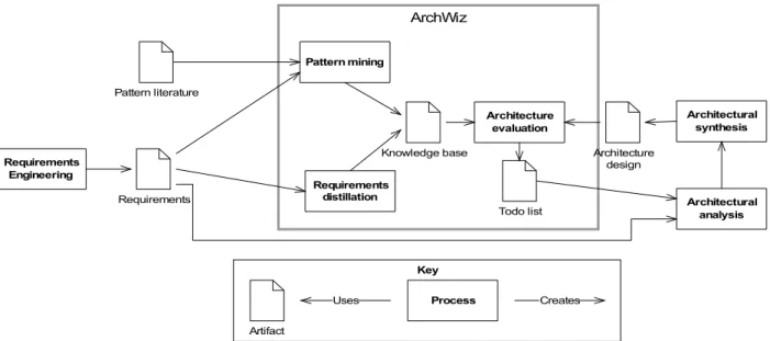
Abstractly seen the ArchWiz has a rather simple system process transformation. Figure 1 shows the system Process Transformation of the ArchWiz. The ArchWiz consists of three processes: Pattern
mining, Requirements distillation, and Architectural evaluation. The main inputs are Pattern literature and Requirements coming from the Requirements Engineering process. In the bottom-up
approach, the Requirements distillation process takes the requirements of a project and distils the reusable parts of them. The results of this process, i.e. reusable requirements, are stored in the knowledge base using the reusable requirements domain model. The reusable requirements are used for an Architectural evaluation of the Architecture design. In a similar way, the top-down approach uses concepts from pattern literature (e.g. responsibilities) using the Usability, Security, or Safety domain models to store the knowledge in the knowledge base, which in turn is used in the
Architectural evaluation process. The Architecture evaluation results in a Todo list, which can be
used in the Architectural Analysis and Synthesis processes to improve the Architecture design. The ArchWiz tool explicitly chooses to focus on a small part of the architecting process and not to try to capture it completely. Consequently, the ArchWiz need to cooperate with a large variety of tools to be used efficiently in the architecting process. Figure 2 shows an overview of these tools. The ArchWiz interacts with the following four types of tools.
Requirement tool - they are used to create and maintain a description of the requirements
for a system. Examples of tools are Door, Word, Rational RequisitePro.
Architecture description tools - they are used to create and maintain the architecture
description. Examples of tools are Word, Powerpoint, Visio, Whiteboard drawing and Enterprise Architect.
Collaboration tools - they are used to share the created Todo-list in the architecture
evaluation to stakeholders of interest. Examples of tools are Lotus Notes, Windows Share Folders and Sharepoint.
Figure 1: System Process Transformation of the ArchWiz.
ArchWiz
Architecture evaluation
Requirements
Todo list
Knowledge base Architecture
design Requirements Engineering Architectural analysis Pattern mining Architectural synthesis Key Process Artifact Creates Uses Pattern literature Requirements distillation
Project management tools - they are used to plan the resulting actions from the Todo-list in
the development process. Examples of tools are Microsoft Project.
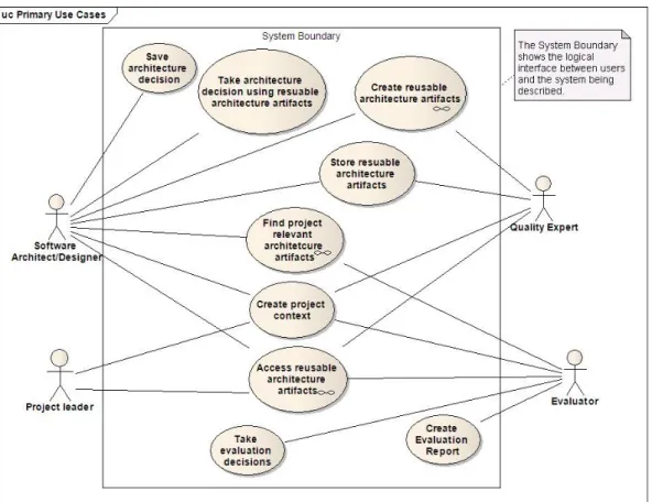
Figure 3 presents the primary uses of the ArchWiz tool. The main actors of the system are software architects or designers, project leaders, quality experts and evaluators. The “Take architecture decision using reusable architecture artefacts” use case is elaborated in figure 4. Figure 5 elaborate on the use case “Access reusable architecture artefacts”.
Figure 2: ArchWiz System Networking.
Requirements tools
Architecture description tools
Collaboration tools
Project management tools ArcWiz Doors Word Word Powerpoint Visio Lotus Notes Sharepoint Windows shared folders Microsoft project Rational Requisite Pro Whiteboard drawings Enterprise Architect Excel
Figure 6 shows a state diagram of how the ArchWiz tool is suppose to operate. When the tool is started the user are able to create a new project or to load an existing project. From the beginning of the ArchWiz project the idea was that the user then should be able to select the knowledge base he or she wanted to work with (e.g. usability, security, safety or reusable requirements). The user execute the evaluation project, can save/export the project, can import other knowledge bases, create a todo-list or shut down. It is also possible to edit the knowledge base, meaning that a user can change and add knowledge to the tool.
Figure 4: Make Architecture Decision.
Figure 5: Navigate Knowledge Views.
uc Access reusable architecture artifacts
ArchWiz Application
Software Architect/Designer(from Actors)
View High-level Architecture
Knowledge
Information Select Information Filter (e.g. Quality,
or Activity) View detailed Architetcure Knowledge Information Navigate between detailed views of Architectural Knowledge uc Take architecture decision using resuable architecture artifacts
ArchWiz Application
Software Architect/Designer(from Actors)
Navigate between detailed views of Architectural Knowledge View made decisions while making a new decision Add a comment to a decision Create decision report
Make a decision for the viewed architectural knowledge View amount of processed knowledge (e.g. percentage of available X)
2.1.1 Changes along the way
The scope of the ArchWiz project was later changed a bit to be more of a requirements tool that only incorporate a general requirements knowledge basis where all software qualities can be represented. A knowledge base existing of reusable requirements for different qualities (the default qualities are usability, security and safety). The user can edit the content of the ArchWiz tool to better suit the project he or she is working on, a todo-list can be created with information about the decisions made for different requirements. The user can comment on each decision. The user should also still be able to import and export other versions of the knowledge base. A feature that was requested from architects at ABB was that the user should be able to split the screen in the tool so that he or she can take decisions on one requirement while viewing the history of decisions at the same time.
2.2. Problem analysis
The thesis work consists of two parts. One part is to help in the development of the new ArchWiz tool. It will probably not be possible to finish the tool but a good foundation should be made. The ones who work on developing the tool until the project ends in December 2009 is me (Caroline Uppsäll), Zafar Bahati (another thesis worker), Anton Jansen at ABB CRC that have some hours each week to help us and Pia Stoll who is the project manager as well as supervisor. The tool is supposed to be implemented in Java/Jigloo and the Eclipse environment which is both a new language and a new environment to learn. There also needs to be some graphical user interfaces implemented which also is new. Time needs to be taken into consideration for learning the language and work environment as well as figuring out how to develop the user interface. It will also take some time to learn the previous work done in the area e.g. the usability supporting architectural patterns. Start-up Shut-down Create New Evaluation Project Execute Evaluation Project Edit Knowledgebase Create todo-list Save/Export Project Choose activity Load existing Evaluation Project Save/Export Knowledge base Select Knowledge base(s) Import Knowledge base Import Knowledge base Select/Create Knowledge base
The second part of the thesis is to come up with suggestions on the domain model for security that contains security entities upon which the ABB software architects can take architectural decisions whether to change the architecture or not to accommodate the security responsibility. To be able to do this a thorough study of the literature in the field needs to be done. With the knowledge gained through the literature together with the ways of using security requirements at ABB today and the way the ArchWiz tool is suppose to work some suggestions of formalisation needs to be addressed.
2.3. Delimitation
It was quite clear from the beginning of the ArchWiz project that the task was to big for the time and resources available. The goal was to get the concepts, the architectural design of the tool and some basic implementation in place by the middle of December 2009 when the project was supposed to be closed.
The delimitation on research was to focus only on the area of security and not to address other qualities. The formalisation is also supposed to be appropriate to the way the tool will be used. From the beginning of the project that was as an evaluation tool but later it was decided that the tool was suppose to be purely for system requirements. This affects the way security will be formalised.
Chapter 3 – Method
This part of the report presents the work flow of this thesis job. It describes which activities have been done in order to get to the results presented at the end of the report, chapter 5.3.1. Workflow
There have been several different activities in this thesis job, how the workflow looked like are presented in figure 7 below. First it was needed to do research regarding the previous work done within the USAP project, since the ArchWiz is a continuation, and on the ArchWiz project which were the project this thesis was made in. To be able to get a deeper understanding of the software area concerned in the project there needed to be some read up on information regarding software architecture in general and also on architectural patterns that helps architects design different aspects of a software system.
When this knowledge was gained the actual work in the ArchWiz tool started with making iterative versions of mock-ups describing the GUI framework of the tool. These was changed multiple times with the help of the project members, the project owner, an expert in user interfaces and an architect that have worked with the USAP prototype tool described in section 4.3. The tools were during this work stripped of functionality. In the first versions of mock-ups there were quite many features that later were removed. The tool was at the first versions thought of as more of a general tool that it was suppose to be. The later mock-ups was more concerned with specific tasks.
After the mock-ups where made it was time to start learning the implementation environment and language. It was decided that the project was supposed to be implemented using the eclipse environment and the Java language, Jigloo was supposed to be used for the graphical elements. Since both the language and the environment were new, some time was needed to set aside to learn and explore them. When knowledge was gained in the language the project members sat down and discussed the design of the implementation. This was later changed when the focus of the tool was simplified but the diagrams made were still useful.
At this point the implementation of the tool needed to start, the tasks were divided and the
implementation of the GUI framework was my tasks to implement. This continued the learning of Jigloo and it took some time before the first implemented version of the GUI framework was done. The time it took was to learn which widgets to use and in what ways, and also how to make the different widgets relate to each other. The first version was made from the mock-ups but the design still changed several times. The process of implementing the GUI framework was enlarged by the slight change of focus in the tool, that made the tool much simpler but the design still needed to be re-maid quite a lot. At the end of the project, in the middle of December 2009, a GUI framework was delivered.
Parallel with the work on the tool I also learned about security in software systems from a variety of books, articles and papers. The subjects were both security in general and security patterns that helps the design and implementation of different security features. After the knowledge was gained I started to work on different suggestions on how to formalise security requirements. These
suggestions were sent to the project's owner for feedback. The resulting suggestions can be seen in section 5.2.
During the entire project, meeting were held at least once a week where the project members meet and discussed the progress in the project as well as divided the work to be done. These meetings were very helpful since it gave a good opportunity to discuss problems and ideas.
The original thought with the report was to write it during the whole thesis job period. This started out quite well with some literature studies but then the work of the design, implementation and security research took more and more time and the thesis report was postponed until the project was closed.
Chapter 4 - Related Work and Theory
In this chapter is some literature studies of areas that the thesis concerns. The areas are Software architecture, architectural patterns, security and security patterns. Each subject is relevant
background information to the ArchWiz work and security research. The rest of the report refers to these sections when discussing the different parts of these subjects.
4.1 Software Architecture
In developing software there are several different design aspects to consider. One of them is
software architecture. But what is software architecture? It is the initial design process that identify the sub-systems of a system and also establishes a framework for how these sub-systems will communicate and be controlled. This initial design process is called architectural design and the output of this design process is a description of the software architecture. [1] and [6] gives the following definition of software architecture.
“The software architecture of a program or computing system is the structure or structures of the system , which comprise software elements, the externally visible properties of those elements, and the relationships among them". - [1] [6]
Architectural design is generally considered as a crucial step to cope with the difficulties of developing large-scale software systems. The software's architecture is a key artefact since it embodies the high-level structures and earliest design decisions. These decisions directly impact on the expected quality attributes and later design or implementation phase. The architecture covers the first design decisions to meet the essential quality requirements for the system [8].
The software architecture encompasses the structure of a larger software system; it is an abstract view of the system. The architecture is concerned with the top-level decomposition of the system into its main components [6]. It’s distilling away details of implementations, algorithms, and data representation and concentrates on the behaviour and interaction of “black-box” elements. The software architecture is the first steps in the design process towards a software system and represents a critical link between the design and requirements engineering process. The architectural design process is concerned with establishing a basic structural framework that identifies the major components of a system and the communication between these components.
4.1.1. Influences to software architecture
An architecture is the result of a set of business and technical decisions. The architect gets
influenced in many different ways and those influences will affect the software architectural design. An architect designing a system for which the real-time deadlines is believed to be tight will make one set of design choices, the same architect designing a similar system in which the real-time deadlines are easily meet will make other design decisions. And if the system doesn’t have any real-time deadlines the architect will most likely make another set of decisions. The architectures will be influenced by the system stakeholders, the developing organisation, the background and experience of the architects and by the technical environment. The architect also affects the factors that
influence them. Figure 8 shows the architect's influences and how the architect affects the factors that influence her [1] [6].
4.1.2. Why is software architecture important
According to [1] [2] there are three reasons for the importance of software architecture.
Communication among stakeholders - The architecture is a high-level presentation of the
system that most, if not all, stakeholders can use as a basis for understanding, negotiation, consensus and communication.
System analysis . Architectural design decisions have a profound effect on whether the
system can meet critical requirements such as performance, security, reliability and maintainability.
Large-scale reuse - A system architecture model is compact and shows how a particular
system is structured and how its elements work together. This model is transferable across systems. In particular, it can be applied to other systems that have similar quality attributes and functional requirements, and therefore it can promote large-scale reuse.
4.1.3 Architectural activities
So, what activities are involved in creating a software architecture, using that architecture to realise a design, and then implementing or managing the evolution of a system or application? These activities include the following [1]:
Creating the business case for the system - Creating a business case is much more than just
assessing the markets need for a system. It is an important step in creating and constraining any future requirements. Questions such as; how much should the system cost? What is its targeted marked? What is its targeted time to market? Will it need to interface with other systems? Etc. must involve the system’s architect. Although these questions cannot be decided only by the architect, he needs to be involved otherwise it may be impossible to achieve the business goals.
Understanding the requirements - There are several different techniques that can be used in
the process of eliciting requirements from the stakeholders and understanding them. For example, use cases, finite-state-machine models, formal specification languages and prototypes. The desired qualities of the system being constructed determine the shape of its architecture, regardless of the techniques used to elicit the requirements.
Creating or selecting the architecture - There might be several different architectural
solutions to a system and the architect need to create and select which architectural solution best suits the problem.
Documenting and communicating the architecture - For the architecture to be able to be
the backbone of the project's design in an efficient way it must be communicated and documented clearly. Developers must understand the work assignments it requires of them, the testers must understand the task structure and management must understand the
scheduling implications it suggests, and so on.
Analysing or evaluating the architecture - In the development of the architectural design
there will be different suggestions of how to build the system. The architects need to analyse all the different suggestions. Choosing between these competing designs in a rational way is one of the architect’s greatest challenges.
Implementing the system based on the architecture - This activity is concerned with
keeping the development fateful to the structure and interaction protocols constrained by the architecture.
Ensuring that the implementation conforms to the architecture - When an architecture is
created and used it goes into a maintenance phase. During this phase it is important to ensure that the actual architecture and its representation remain faithful to each other.
4.1.4. What makes a “good” architecture?
With the same technical requirements for a system, two different architects in different
organisations will, because of their different influences, produce different architectures. How can we then know which architecture is the right one? There is no such thing as good or bad
architectures; but they can be more or less fit for the system. There are a number of rules of thumb that should be followed when designing an architecture [1].These rules of thumb are divided into process recommendations and structural recommendations.
The process recommendations are:
The architecture should be the product of a single architect or a small group of architects
with an identified leader.
The architect should have the functional requirements for the system and a prioritised list of
quality attributes that the architecture is expected to satisfy.
The architecture should be well documented.
The system’s stakeholders should be actively involved in the reviews of the architecture. The architecture should be analysed for applicable quantitative measures (e.g. maximum
throughput) and formally evaluated for quality attributes before it is too late to make changes to it.
The architecture should lend itself to incremental implementation.
The architecture should result in a specific set of resource contention areas, the resolution of
which is clearly specified, circulated and maintained.
The structural recommendations are:
The architecture should feature well-defined modules whose functional responsibilities are
allocated in the principles of information hiding and separation of concerns.
Each module should have a well-defined interface that encapsulated changeable aspects. Quality attributes should be achieved using well-known architectural tactics.
The architecture should never depend on a particular version of a commercial product or
tool.
Modules that produce data should be separated from modules that consume data, this
increases modifiability.
The architecture for parallel- processing systems should feature well-defined processes or
tasks that do not necessarily mirror the module decomposition structure.
Every task or process should be written in such a way that its assignment to a specific
processor can be easily changed.
The architecture should feature a small number of simple interaction patterns. This means
that the system should do the same thing in the same way throughout.
4.1.5. Architectural Patterns, Reference Models, and Reference Architectures
The first of starting points for an architecture leads through a number of intermediate stages to a full architecture with all the appropriate information about the system filled in. Each stage represents the outcome of a set of architectural decisions. Here is the definition of three of them [1] [5]. The relationships among them can be seen in figure 9.
Architectural Patterns
An architectural pattern is a description of elements and relations, together with a set of constraints on how they may be used. Pattern helps building the system on the experiences of skilled software engineers. Architectural patterns capture existing, well-proven experience in software development and help to promote good design practice. Every pattern deals with a specific and recurring problem in the design or implementation of a software system [3]. More about what a pattern is and how it can be used can be found in section 4.2.
Reference Model
A reference model is a division of functionality together with data flow between the pieces. A reference model is a standard decomposition of a known problem into parts that together solve the problem.
Reference Architecture
A reference architecture is a reference model mapped into software elements and the data flows between them. As stated above a reference model divides the functionality, the reference architecture is the mapping of that functionality onto a system decomposition.
Important to mention here is that reference models, architectural patterns and reference architectures are useful concepts that capture elements of an architecture, but they are not architectures. Each one of them is the outcome of early design decisions.
Figure 9: Relationships between Architectural Pattern, Reference Model, Reference Architecture. After [1]
4.1.6. Architectural structures and views
Today a software system is far too complex to be understood all at once. Therefore we restrict our attention (at one time) to one or a small number of the software system’s structure. So, when a system is discussed it is important to make clear which view we are taking in the architecture. A view is a representation of a coherent set of architectural elements. It consists of a set of elements and the relations among them. A structure is the set of elements itself, as they exist in software or hardware.
Architectural structures can be divided into three groups (module structures, component-and-connector structures and allocation structures [1] [5] [8]), these depend on the nature of the elements they show. These three structures correspond to the three broad types of decisions that architectural design involves:
➢ How is the system to be structured as a set of code units (modules)?
➢ How is the system to be structured as a set of elements that have runtime behaviour
(components) and interactions (connectors)?
➢ How is the system to relate to non-software structures in its environment (i.e. CPUs, file
systems, networks, development teams, etc.)?
The software structures that are described in this chapter are some of the most common and useful structures [1], they are shown in figure 10.
Module structures
Here the elements are modules, which are units of implementation. They consider a code-based way of considering the system. The modules assign areas of functional responsibility. The module structures helps answering questions such as what is the primary functional responsibility assigned to each module? What other software elements is a module allowed to use? And what other
software does it actually use? Module based structures include decomposition, uses, layered and class.
Component-and-connector structures
Here the elements are runtime components and connectors. Component-and-connector structures helps answering questions such as what are the major executing components and how do they interact? What are the major shared data stores? Which parts of the system are replicated? How does data progress through the system? Component-and-connector structures include process, concurrency, shared data and client-server.
Allocation structures
The allocation structures show the relationship between the software elements and the elements in external environments in which the software is created and executed. These structures answer questions like what processor does each software elements execute on? In what files is each element stored during development, testing and system building? And what is the assignment of software elements to development teams? Allocation structures include deployment, implementation and work assignment.
As mentioned these structures are only a few and there are many more out there. Of course an architect should not use all of them even though most of them will in fact exist in the system. Each of these structures provides a different perspective and design handle on a system, and each is valid and useful. But they are not independent; elements of one structure will be related to elements of another.
Table 1 shows a summary of the above structures. The table lists the relations in each structure as well as why is it useful.
Table 1: Architectural structures of a system.
Software structures
Relations Useful for
Module structures
Decomposition Is a submodel of; Shares secret with
Resource allocation and project structuring and planning;
Information hiding, encapsulation; Configuration control
Uses Requires the correct presence of Engineering subsets; Engineering extensions
Layered Requires the correct presence of; Uses the services of;
Provides abstraction to
Incremental development; Implementing systems on top of “virtual machines” portability Class Is an instance of;
Shares access methods of
In object-oriented design systems, producing rapid almost-alike implementations from a common template
Component-and-connector structures
Process Runs concurrently with; May run concurrently with; Excludes; Precedes; etc.
Scheduling analysis; Performance analysis
Concurrency Runs on the same logical thread Identifying locations where resource contentions exists, where threads may fork, join, be created or be killed
Shared data Produces data; Consumes data
Performance; Data integrity; Modifiability
Client-server Communicates with; Depends on
Distributed operation; Separation of concerns; Performance analysis; Load balancing;
Allocation structures
Deployment Allocated to; Migrates to
Performance analysis; Availability analysis; Security analysis
Implementation Stored in Configuration control, integration, test activities
Work assignment Assigned to Project management, best use of expertise, management of commonality
4.2 Patterns
The term patterns are frequently used when dealing with architecture and design. But what is a pattern and how is it used?
Patterns are a way to use the experiences of other developers and collect experiences of skilled software engineers. The patterns capture existing and well-proven experiences in software
engineering and help to promote good design practice. Each pattern solves a specific problem that recurs in software development, both in the design and implementation phase. This report will focus on the patterns used in architectural design.
It is very unusual that experts working on a particular problem solve it by making an entirely new solution that stands all alone from existing ones. When they work they often recall a similar
problem that they have already solved and uses that as reference when investigating the solution for the problem. Abstracting from these problem-solution pairs and filter out common factors leads to patterns. The term pattern has been defined as follows:
“Each pattern is a three-part rule, which expresses a relation between a certain context, a problem and a solution.
As an element in the world, each pattern is a relationship between a certain context, a certain system of forces which occurs repeatedly in that context, and a certain spatial configuration which allows these forces to resolve themselves.
As an element of language, a pattern is an instruction, which shows how this spatial configuration can be used, over and over again, to resolve the given system of forces, wherever the context makes it relevant.
The pattern is, in short, at the same time a thing which happens in the world, and the rule which tells us how to create that thing. and when we must create it. It is both a process and a thing: both a description of a thing which is alive, and a description of the process which will generate that thing.” - Christopher Alexander [11].
A pattern can be characterised as:
“A solution to a problem that arises within a specific context”. - [9].
In [14] patterns are described as:
general design problem in a particular context. - [14]
With the use of patterns, solutions to specific problems get more available instead of just existing in the minds of experts.
4.2.1 Why patterns?
Typically a pattern describes several classes, components and details as well as the relationships among them and their responsibilities. All these elements together solve the problem at hand. This means that patterns identify and specify an abstraction on a higher level then single classes or components. If the names of patterns are carefully chosen they become part of a design language that is widespread. Patterns that have been established in the design language facilitate effective discussions of design problems and their solutions. The discussions get more effective since the need of explaining a solution to a particular problem in detail is no longer necessary. Instead a pattern name can be used and the way this pattern can be used in the architecture can be explained. Patterns are also a means of documenting software architectures. They can describe the vision the architect has in mind when designing a software system. This helps other to avoid violating this vision when extending or modifying the original architecture or code. If the architect documents that a part of an architecture is made according to a specific pattern others know how to extend and modify that pattern.
Another benefit of using patterns is that they help building complex and various software
architectures. As already mentioned each pattern provides a predefined set of components, roles and relationships. It can be used to specify certain aspects of concrete software structures. This means that patterns can be used as building-blocks when constructing more complex systems. Using the kind of solutions that patterns bring both speeds up the development of the design and increase the quality of it. This doesn't say that individual patterns will in all cases be better than other solutions but patterns can at least then be used to help evaluate and assess design alternatives. One thing to keep in mind is that patterns specify the basic structure of the solution to a problem and not a fully detailed solution. In other words, patterns don't provide complete solutions but they help solve problems.
Another benefit or patterns is that they support the construction of software with defined propertied since they provide a skeleton of functional behaviour. Since every pattern describes a proven way to handle the problem it addresses there is no need to waste time inventing a new solution when encountering a design problem that is covered by a pattern. If the pattern is implemented correctly it can be relied on.
After this the following definition can be made:
“A pattern for software architecture describes a particular recurring design problem that arises in specific design contexts, and presents a well-proven generic scheme for its solution. The solution scheme is specified by describing its constituent components, their responsibilities and relationships, and the way in which they collaborate.” - [3].
4.2.2 What makes a pattern
One could say that a pattern is built on a three-part schema:
Context - a situation giving arise to a problem.
Problem - the recurring problem arising in that context. Solution - a proven resolution of the problem.
This schema captures the essence of a pattern independent of its domain and it underlies many pattern descriptions. The above schema makes it easy to understand, share and discuss patterns.
Even though these three parts are closely coupled they have to be clarified in separation to understand the schema in detail.
Context
The context of a pattern might be quite general; it describes situations in which the problem occurs. An example is 'developing software with a human-computer interface'. The context can also tie different patterns together. A pattern can occur in the context of another pattern. It is really difficult to create a context for a pattern since it is fairly impossible to determine all situations in which a pattern can be applied.
Problem
This part of a pattern schema describes the repeated problem in the context. It begins with a general problem specification that captures the essence. This problem specification is often complemented with a set of forces that is any aspects of the problem that should be considered when solving it. Forces are the key to solving the problem. If the forces are balanced in a good way the solution to the problem will be better.
Solution
This part of the pattern schema shows how to solve the problem, or in other words how to balance the forces associated with the problem. This solution might not solve all the forces to the problem, which is important to beware of. Sometimes it focuses on particular forces and leaves others half or completely unresolved. In software architecture the solution includes two aspects. The first is that each pattern specifies a certain structure. This structure addresses the static aspect of the solution. A configuration of elements. It consists of both components and their elements. The second aspect is that every pattern specifies run-time behaviour. This behaviour addresses the dynamic aspects of the solution. This means questions like how do the participants of the pattern collaborate? How is work organised between them? And how do they communicate with each other?
A pattern provides a solution schema and not a fully-specified artefact. The solution in the pattern should be able to be reused in many implementations. But the essence still needs to be unchanged. When an architect chooses to apply a specific pattern in the design it means that the particular structure it provides should be included, but the architect needs to adjust the design and tailor it to the specific needs of the problem which is under design. It is unlikely that two implementations of the same patterns are exactly the same.
The three-part schema can be summarised in the following picture (figure 11) [3].
Figure 11: Summary of the three-part schema. After [3]
Pattern
Context
Problem
Solution
Design situation giving rise to a design problem
Set of forces repeatedly arising in the context
Configuration to balance the forces
Structure with components and relationships Run-time behaviour
4.2.3 Categories of Patterns
Patterns cover a various range of scale and abstraction and they can be grouped into three categories of patterns.
Architectural Patterns Design Patterns Idioms
This thesis report will focus on the architectural patterns but the other two categories will also be explained.
Architectural Patterns
The architectural patterns are used to describe how to solve some overall structuring principles according to which the architecture is built. A definition of architectural patterns is:
“An architectural pattern expresses a fundamental structural organisation schema for software systems. It provides a set of predefined subsystems, specifies their
responsibilities, and includes rules and guidelines for organising the relationships between them.”. - [3]
Architectural patterns specify the structural properties of an application and they are templates for concrete software architectures. The selection of an architectural pattern is therefore a fundamental design decision when developing a software system.
Design Patterns
The design patterns are used when describing the subsystems of a software architecture and the relationships between them. A definition of design patterns is:
“A design pattern provides a schema for refining the subsystems or components of a software system, or the relationships between them. It describes a commonly-recurring structure of communication components that solves a general design problem within a particular context.”. - [3]
These patterns are smaller in scale then the architectural patterns but they tend to be independent from programming languages. Many design patterns provide structures for decomposing more complex services or components.
Idioms
Idioms are on a lower level then design patterns. They deal with the implementation of certain design issues. A definition of idioms is:
“An idiom is a low-level pattern specific to a programming language. An idiom describes how to implement particular aspects of components or the relationships between them using the features of the given language”. - [3]
Most idioms are language specific and they represent the lowest level of patterns. They address the aspects of both design and implementation. Since the idioms are language specific the same idiom look different for different languages.
4.2.4 Relationships between patterns
Just because pattern focuses on providing a solution for resolving one specific problem doesn't mean they are independent from each other, there are many relationships among patterns. For
example the solutions from one pattern can often be implemented with help of other patterns. This kind of relationship between patterns means that each pattern depends on the smaller patterns it contains and on the larger patterns in which it is contained. Another kind of relationship between patterns is variations and combinations. The relationships between patterns are what make it possible to put them together to form a full architectural design for a system that is coherent and consistent. These relationships are very important because without them the patterns would only be able to solve isolated problems with no or very limited effect on the larger design [9].
When creating these relationships between pattern and putting them together, pattern languages are created. As already mentioned pattern supports the solutions of smaller development problems but they cannot themselves support the solution of an entire system. To support the development of a particular family of software systems or application frameworks a broader view must be taken on the patterns. The patterns need to be woven together in such a way that they together resolve the problems of the software development. The result of putting all these patterns together in a way so that they resolve the bigger problem is what pattern languages are. They are not languages in the sense that they are formal languages but they do provide a vocabulary for talking about certain problems [10]. Many patterns form a language, just as words must have grammatical and semantic relations to each other to form a useful language, patterns must have relations to each other to form a pattern language.
Christopher Alexander describes the concept of pattern languages as follows:
The elements of a pattern language are patterns. There is a structure on the patterns, which describes how each pattern is itself a pattern of other smaller patterns. And there are also rules, embedded in the patterns, which describe the way that they can be created, and the way that they must be arranged with respect to other patterns.
However, in this case, the patterns are both elements and rules, so rules and elements are indistinguishable. The patterns are elements. And each pattern is also a rule, which describes the possible arrangements of the elements-themselves again or other patterns. - [12]
4.2.5 Description
If a pattern should be easy to understand and discuss it needs to be described in a good way. A good description of the pattern helps to understand the essence of it and also to implement it as well as consider the consequences of using it. There are different ways of describing patterns but it is important that they are described uniformly, if it is, it's easy to compare patterns with each other. The following is a uniform way to describe patterns that are frequently used, most patterns look something like this: Each pattern have a name, that is a descriptive name of the pattern and often also a short summary. Also Known As lists other names under which the same pattern is known.
Example, this is a real-world example of how to use the pattern, it also expresses the need for the
pattern. Context is as discussed above the situation in which the pattern may be applied. Problem is also discussed above and describes the problem the pattern addresses together with a listing of its forces. Solution this is as stated above the fundamental solution principle underlying the pattern.
Structure is a detailed specification of the structural aspects of the pattern. Dynamics is typical
scenario that describes the run-time behaviour of the pattern. Implementation, this is guidelines for how to implement the pattern. These implementation details needs to be looked at as suggestions and not rules. Example Resolved discusses the important aspects of resolving the example. These are aspects that are not considered in the solution, structure, dynamics and implementation sections.
Variants gives a brief description of variants and specialisation of a pattern. Known Uses is
example, taken from existing systems, of the use of the pattern. Consequences lists the benefits and possible liabilities of the pattern. And finally See Also that refers to other pattern that solve similar
problems. And also to pattern that help refine the described pattern [3] [9] [14]. All patterns don't follow this precise template but they tend to have a very similar description as this one.
4.2.6 Patterns in Software Architecture
Architectural patterns are a key concept in the field of software architecture and as already
mentioned they are software patterns that offer a well-established solution to architectural problems in software engineering. An architectural pattern expresses a fundamental structural organisation schema for a software system that consists of subsystems, their responsibilities and interrelations. As also mentioned above, architectural patterns are larger in scale than design patterns. The
architectural patterns facilitate communication between stakeholders through a common vocabulary. One of the most important aspects of architectural patterns is that they embody different quality attributes such as usability, security, safety, performance, maintainability etc. Different architectural patterns represent solutions to different problems in different qualities. In the early design phase a software architect makes a choice of which architectural patterns best provide the systems desired qualities [13].
Important to remember is that architectural patterns are not architectures as such, it is rather a concept that captures essential elements of a software architecture. Many different architectures may implement the same patterns therefore they share the same characteristics, but they do not solve the same problem.
Another point to be aware of is that there are two different schools of thoughts in the literature with respect to the nature of architectural patterns. One uses the term “architectural patterns” and the other uses the term “architectural style”. Both architectural patterns and architectural styles refers to recurring solutions to problems at the architectural design level, and they both provide a common vocabulary. They both also accept that patterns provide the means to reason for quality attributes and help to document the design decisions taken by the architect. Architectural patterns and architectural styles are complementary mechanisms for encapsulating design expertise. So while they are basically the same they do have some key differences. Styles provide a collection of building-block design elements, rules and constraints for composing the building blocks, and tools for analysing and manipulating designs created in the style. Styles generally provide guidance and analysis for building a broad class of architectures in a specific domain. Patterns focus on solving smaller, more specific problems within a given style, or perhaps multiple styles. Patterns do not need to be architectural. The differences are described more below [7] [13].
Architectural patterns
The architectural patterns perspective, patterns are considered as problem-solution pairs that occur in a given context. It does not only document how a solution solves the problem but also why, the rationale behind the solution. The documentation of a pattern gives much attention to the forces that shape the problem. As described in section 4.2.2 a description on an architectural pattern is based on the context-problem-solution schema and may be extended with further details. As also
described above in, in this section, the patterns are meant to work together in pattern languages and have therefore numerous dependencies among each other. If a solution should qualify as a pattern it has to capture some common practices and the solution needs to be non-obvious.
Architectural styles
In the architectural styles perspective the problem or rationale behind it does not get much attention. Styles are described as components, connectors and issues related to control and data flow and the constraints upon them. Its attention is drawn to architectural configurations, semantics of the style and potential architectural analysis that can be performed in the system built on the style. In this way the styles become more concrete and focused. This leads to multiple variations of the same pattern in order to solve specialised design problems.
As discussed in the precious sections of this chapter patterns are the focus in this report. In theory an architectural pattern is on a higher level then design patterns but in reality it is quite hard to draw a line between the two. It is in many cases not clear when a pattern is “big” enough to be considered as architecture. So it is not uncommon that design patterns are referred to or used as architectural patterns. What is architecture and what is design is often decided upon the designers or architects point of view. Examples of some architectural patterns are [3]:
Layers - Helps to structure applications that can be decomposed into groups of subtasks in
which each group of subtask is at a particular level of abstraction. An example is the networking protocols.
Model-View-Controller - Divides an interactive application into three components (model,
view and controller). The model contains the core functionality and data. Views display information to the user. Controllers handle user input. Views and controllers together comprise the user interface. A change-propagation mechanism ensures consistency between the user interface and the model.
Pipe and filer architecture - Provides a structure for systems that process a stream of data.
Each processing step is encapsulated in a filter component. Data is passed through pipes between adjacent filters. Recombining filters allows building families of related systems.
Blackboard system - Useful for problems for which no deterministic solution strategies are
known. In Blackboard several specialised subsystems assemble their knowledge to build a possibly partial or approximate solution.
Client-Dispatcher-Server - Introduces an intermediate layer between clients and servers, the
dispatcher component. It provides location transparency by means of a name service, and hides the details of the establishment of the communication connection between clients and servers.
4.3 Usability-Supporting Architectural Patterns (USAP)
There exist a number of important quality attributes that must be considered in the architecture of a system. Some of these qualities are availability, modifiability, performance, security, safety,
testability and usability.
During 2007 and 2008 ABB CRC and the Software Engineering Institute (SEI)/Carnegie Mellon University in Pittsburgh, USA conducted a project called the USAP (Usability-Supporting Architectural Patterns) Project. The research in the USAP project was to find a way to formalise usability as an architectural concern. This formalisation was then supposed to help architects think about usability early in the design process. The project resulted in contemporary research that contributed to the field of usability and software architecture in the domain of Software
Engineering. The project also resulted in a web-based tool at prototype state. The work with the USAP project and the results are described in this chapter.
4.3.1. USAP project
There exist different techniques for qualities such as performance, reliability and maintainability among others when it comes to designing the architecture of a system. Usability is also a very important quality but for some reason it gets little attention in the architectural phase of the
development process. Usability has been treated as a subquality of modifiability which means that it is treated in such a way that the usability issues that arise during testing can be handled with just some modifications. This is a problem, because many usability concerns reach deep into a systems architecture and can therefore not be treated by just separating the interface from the functionality. The effect of treating usability as a problem in modifiability simply postpones many of the usability


![Figure 8: The architect's influences. After [1].](https://thumb-eu.123doks.com/thumbv2/5dokorg/4905040.134908/18.892.167.725.94.424/figure-the-architect-s-influences-after.webp)
![Figure 10: Architectural structures. After [1]](https://thumb-eu.123doks.com/thumbv2/5dokorg/4905040.134908/21.892.168.728.536.776/figure-architectural-structures-after.webp)
![Figure 12: Relationships between USAPs. After [19]](https://thumb-eu.123doks.com/thumbv2/5dokorg/4905040.134908/31.892.230.682.229.513/figure-relationships-between-usaps-after.webp)
![Figure 15: Concepts that influence and are influenced by security requirements. After [26]](https://thumb-eu.123doks.com/thumbv2/5dokorg/4905040.134908/38.892.196.708.102.852/figure-concepts-influence-influenced-security-requirements.webp)
