A pre-study for functional coatings evaluated on light metals to be
applied on a new HPDC Mg-alloy
Investigating tribological and thermophysical properties,
as-cast and coated
PAPER WITHIN Materials Science and Surface Technology AUTHOR: Louise Albo Zieme, Pontus Bergstedt
TUTOR:Rohollah Ghasemi JÖNKÖPING June 2021
I
materials science and surface technology. The work is a part of the two-year Master of Science programme “Product Development and Materials Engineering”. The authors take full responsibility for opinions, conclusions and findings presented.
Examiner: Anders E.W Jarfors Supervisor: Peter Leisner Scope: 30 credits (second cycle) Date: June 2021
II
Abstract
Magnesium with two-thirds of the density compared to aluminium and one-quarter of steel, intrigues product developers and material scientists due to the light metal’s excellent combination of strength to weight ratio as well as their capability of being produced as a High Pressure Die Cast component compared to other ferrous or light metal alloys.
However, a magnesium alloy inherits some concerning drawbacks, limiting the exploitation in structural applications and mechanical design such as automotive, heavy machinery and aerospace components. The need for a magnesium alloy that could withstand a sufficient amount of wear, temperature and corrosive environment, leads towards the investigation and evaluation of a suitable, functional coating as a solution to exploit the evident advantages a magnesium alloy exhibits. A substantial amount of research is required in order to reduce an existing knowledge gap that is the ongoing development in the search for a sufficient functional coating and adherence capability to the highly reactive substrate that is a magnesium alloy. This industrial master thesis is an early stage investigation to evaluate how the currently used aluminium substrate with an electrodeposited coating relate and compares to a heat-treated electroless deposited coating through tribological and thermophysical induced stresses. These properties are tested with proven industrial standard methods resulted in a comprehensive conclusion and discussion regarding the feasibility of applying the coating onto a commercial magnesium alloy closely related to the Mg-alloy developed by Husqvarna and thereby contributing to technological advances to the highly relevant topic within product development in materials engineering.
Summary Pontus Bergstedt
III
Summary
There is a high demand and interest to replace High Pressure Die Cast (HPDC) aluminium parts and components with HPDC magnesium alloys, particularly in applications and products where a reduction of weight is of importance. Due to high reactivity and other inadequate properties, major challenges arise when developing a new magnesium alloys contributing as a structural component. Surface coating technology is commonly utilized to compensate or even enhance intendent functions by encapsulation.
This industrial master thesis is an early investigation to evaluate how the currently used aluminium substrate coated with electrodeposited Ni-SiC relate and compares to a heat-treated electroless deposited NiP-SiC coating through tribological and thermophysical induced stresses. These properties are tested with proven industrial standard methods resulted in a comprehensive conclusion and discussion regarding the feasibility of applying the NiP-SiC coating onto a commercial magnesium alloy which is similar to the Mg-alloy developed by Husqvarna.
The temperature range, from room temperature to 400 degrees Celsius, was used during the evaluation of the specific heat capacity, thermal diffusivity, thermal expansion, resulting in a representable thermal conductivity for each of the tested coatings applied onto the commercial Al EN46000 substrate. To be able to draw any conclusions regarding the thermal behaviour of the specific coating, an evaluation of raw Mg, AE44 and Al EN46000 was carried out as an essential understanding of the thermophysical properties of the substrate which would lead to discussions how the coating would behave applied to other substrates. The Ni-SiC and NiP-SiC coating with comparable thickness, showed prominent thermal conductivity results, without any distinguishable favour between the two.
Reciprocating dry sliding wear experiments were conducted using a suitable and comparable force of 25 N with a counterpart made of lamellar graphite iron, other variable parameters to establish different behaviours of the inflicted wear situations was evaluated. It was evident that wear is a complex system where the decision of two surfaces is crucial for the outcome where one of the prominent parameters is hardness, leading to favourable outcome for the NiP-SiC coatings.
Fundamental and supporting experiments were conducted associated to the reciprocating dry sliding wear experiment to conclude the wear behaviour. The effect of heat treatment of the phosphorus contained coating excelled over the non-treated one, twice the hardness was achieved.
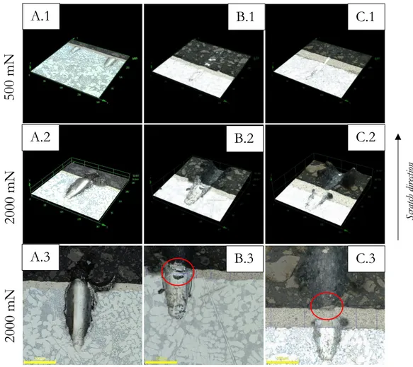
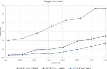
Progressive scratch experiment was executed to evaluate the characteristics of the coatings during a progressively applied load up to 2700 mN. The heat-treated coating, containing phosphorus retained once more advantageous over the softer coating during the progressive scratch test.
An investigation regarding the adhesion between the coating and the substrate was also performed to examine the adherence properties of the electro- and electroless deposited coatings as a reference for future feasibility on the newly developed Mg-alloy, where none of the performed tests demonstrated any distinguishable adhering issues, tested on an aluminium substrate.
Due to novelty of the work, it is believed that this attempt provides an important understanding, methodology and knowledge to further develop and evaluate an applicable coating onto the newly developed Mg-alloys by Husqvarna AB, and thereby contributing to technological advances to the highly relevant topic within product development in materials engineering.
Keywords: reciprocating dry sliding wear test, thermophysical test, NiP-SiC, Ni-SiC, functional coatings,
IV
Acknowledgement
Acknowledging gratitude towards our supervisors for the help, support and endeavour, with the aim for excellency in every step of the project.
Peter Leisner and Rohollah Ghasemi
We are especially grateful for the support and helpful discussions from. Esbjörn Ollas
Jacob Steggo Johan Börjesson Tony Bogdanoff
Last but not least we want to thank all the people at Materials and Manufacturing department at School of Engineering and the people encountered in the material lab at Husqvarna, that have helped us.
Content Pontus Bergstedt V
Table of Content
1 INTRODUCTION ... 1 1.1 BACKGROUND ... 1 1.1.1 Husqvarna Group ... 21.1.2 Surface treatment through coating ... 2
1.2 PURPOSE AND RESEARCH QUESTIONS ... 2
1.3 DELIMITATIONS ... 3
1.4 OUTLINE ... 4
2 THEORETICAL BACKGROUND ... 5
2.1 CHARACTERISTICS OF THE MATERIALS IN QUESTION ... 5
2.1.1 Microstructure ... 5
2.1.2 Magnesium ... 5
2.1.3 Aluminium ... 6
2.2 HIGH PRESSURE DIE CASTING (HPDC) ... 6
2.3 COATING TECHNIQUES ... 7
2.3.1 Electroless plating of Nickel-Phosphorus ... 7
2.3.2 Electroplating of Nickel ... 8 2.3.3 Dispersion plating ... 8 2.4 TRIBOLOGICAL PROPERTIES ... 9 2.4.1 Scratch ... 9 2.4.2 Reciprocating wear ... 10 2.5 THERMOPHYSICAL PROPERTIES ... 13
2.5.1 Specific heat capacity ... 13
2.5.2 Thermal diffusivity ... 14
2.5.3 Thermal expansion ... 14
2.5.4 Thermal conductivity ... 15
3 METHOD AND IMPLEMENTATION ... 16
3.1 SAMPLE PREPARATION ... 16
3.2 POLISHING OF SAMPLES ... 17
3.3 ANALYSIS USING MICROSCOPE ... 18
3.4 HARDNESS TEST ... 18
3.5 ADHESION ... 18
3.6 PROGRESSIVE SCRATCH EXPERIMENT ... 18
3.7 RECIPROCATING DRY SLIDING WEAR EXPERIMENT ... 19
3.8 THERMOPHYSICAL PROPERTIES ... 21
3.8.1 Thermal expansion ... 21
3.8.2 Specific heat capacity ... 22
3.8.3 Thermal diffusivity ... 22
3.8.4 Thermal conductivity ... 22
4 FINDINGS AND ANALYSIS ... 23
4.1.1 Al EN46000 – as-cast and coated ... 23
4.2 TRIBOLOGICAL EXPERIMENTS ... 25
VI
5 DISCUSSION ... 39
5.1 DISCUSSION OF METHOD ... 39
5.2 DISCUSSION OF FINDINGS ... 40
5.3 COMPARISON BETWEEN COATINGS ... 43
6 CONCLUSIONS ... 44
7 FUTURE RESEARCH ... 45 8 REFERENCES ... I
Content Pontus Bergstedt
VII
Table of figures
FIGURE 1.HIGH PRESSURE DIE CASTING ... 6
FIGURE 2.ION EXCHANGE PLATING ... 7
FIGURE 3.AUTOCATALYTIC PLATING ... 7
FIGURE 4.ILLUSTRATION OF AN ELECTROPLATING PROCESS ... 8
FIGURE 5.COATING DISTRIBUTION ... 8
FIGURE 6.SCHEMATIC OF THE MICRO HARDNESS AND SCRATCH MACHINE ... 9
FIGURE 7.TERMINOLOGY FOR WEAR AND THEIR INTERRELATIONS ... 10
FIGURE 8.ILLUSTRATING WEAR STAGES ... 10
FIGURE 9.PARTICLES INTEGRATED IN THE SURFACE ... 11
FIGURE 10.PARTICLES MOVING BETWEEN TWO SURFACES ... 11
FIGURE 11.ADHESIVE WEAR ... 11
FIGURE 12.2.4.2.3TRIBO-OXIDATIVE WEAR ... 12
FIGURE 13.STICK-SLIP &SPRAG-SLIP ... 12
FIGURE 14.THERMAL CONDUCTIVITY FOR DIFFERENT MATERIALS ... 15
FIGURE 15.TREE REPRESENTATION OF METHOD CHAPTER ... 16
FIGURE 16.A)HPDC BISCUIT & INGATE ... 16
FIGURE 17.A)MACHINED BISCUIT FOR RECIPROCATING DRY SLIDING WEAR TEST ... 16
FIGURE 18.SAMPLE PREPARATIONS FOR THERMAL TESTS ... 17
FIGURE 19.A)OLYMPUS DSX1000B)LYRA3TESCAN ... 18
FIGURE 20.A)SCHEMATIC VIEW OF PROGRESSIVE LOAD B)INDENTER ... 19
FIGURE 21.RECIPROCATING DRY SLIDING WEAR MACHINE ... 19
FIGURE 22.ILLUSTRATION OF SAMPLE BEFORE AND AFTER PREPARING FOR WEAR TEST ... 20
FIGURE 23.WEIGHT PROCEDURE - WEAR TRACK & PIN ... 20
FIGURE 24.TREE REPRESENTATION OF THERMAL PROPERTIES ... 21
FIGURE 25.SHIMADZU TMA-50, THERMAL EXPANSION ... 21
FIGURE 26.KERN ABS-A02, DENSITY -ARCHIMEDES PRINCIPLE ... 21
FIGURE 27.NETZSCH DSC-404C, SPECIFIC HEAT CAPACITY ... 22
FIGURE 28.NETZSCH LFA427, THERMAL DIFFUSIVITY ... 22
FIGURE 29.A)MICROSTRUCTURE FROM BISCUIT B)MICROSTRUCTURE FROM INGATE ... 23
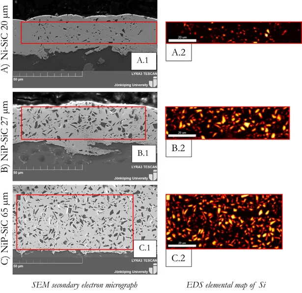
FIGURE 30.A)NI-SIC COATING 20 µM B)NIP-SIC COATING 27 µM C)NIP-SIC COATING 65 µM ... 24
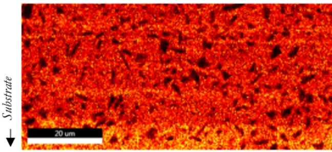
FIGURE 31.EDS ELEMENTAL MAPPING OF PHOSPHORUS ... 25
FIGURE 32.HARDNESS RESULTS 50GR HV AND HK ... 25
FIGURE 33.A)NI-SICB)NIP-SIC27 µM C)NIP-SIC65 µM ... 26
FIGURE 34.PROGRESSIVE SCRATCH PROFILE 2700 MN:A)NI-SICB)NIP-SIC27 µM C)NIP-SIC65 µM ... 27
FIGURE 35.PROGRESSIVE LOAD SCRATCH FOR AL EN46000 COATED WITH NI-SIC AND NIP-SIC ... 27
FIGURE 36.WEAR LOSS RATE FOR NI-SIC&PIN ... 28
FIGURE 37.A)CONTOUR AND HEIGHT B)WEAR DEBRIS C)SEM,EDS OF NI-SIC,480 S ... 29
FIGURE 38.A)CONTOUR AND HEIGHT B)WEAR DEBRIS C)SEM,EDS OF NIP-SIC27 µM,480 S ... 30
FIGURE 39.A)PIN USED FOR NI-SIC480 S B)PIN USED FOR NIP-SIC480 S ... 31
FIGURE 40.A)WORN PIN USED FOR NI-SIC480 S B)WORN PIN USED FOR NIP-SIC480 S ... 31
FIGURE 41.NIP-SIC27 µM,1000 S ... 32
FIGURE 42.NIP-SIC65 µM,1000 S ... 32
FIGURE 43.THERMAL ANALYSIS RESULTS FOR RAW MG:(A)SPECIFIC HEAT CAPACITY,(B)THERMAL DIFFUSIVITY,(C)DENSITY &(D) THERMAL CONDUCTIVITY ... 33
FIGURE 44.THERMAL ANALYSIS RESULTS FOR THE COMMERCIAL ALLOY AE44:(A)SPECIFIC HEAT CAPACITY,(B)THERMAL DIFFUSIVITY, (C)DENSITY &(D)THERMAL CONDUCTIVITY ... 34
VIII
FIGURE 45.THERMAL MEASUREMENTS RESULT FOR AL EN46000 UNCOATED (TWO DIFFERENT RUNS ON THE SAME SAMPLE) ... 35
FIGURE 46.THERMAL MEASUREMENT RESULTS FOR AL EN46000 ALLOY COATED WITH NI-SIC(20 µM)(TWO DIFFERENT RUNS ON THE SAME SAMPLE) ... 36
FIGURE 47.THERMAL MEASUREMENT RESULTS FOR AL EN46000 COATED WITH NIP-SIC(27 µM)(TWO DIFFERENT RUNS ON THE SAME SAMPLE) ... 37
FIGURE 48.THERMAL MEASUREMENT RESULTS FOR AL EN46000 COATED WITH NI-P-SIC WITH THICKNESS OF (65 µM)(TWO DIFFERENT RUNS ON THE SAME SAMPLE) ... 38
FIGURE 49.WEAR TRACK NI-SIC480S ... 40
FIGURE 50.THERMAL CONDUCTIVITY RESULTS PERFORMED ON BISCUIT AND INGATE SAMPLES SELECTED FROM AS-CAST HPDCMG -AE44 ALLOY ... 41
FIGURE 51.SAMPLE PREPARATION FOR THE THERMAL EXPERIMENTS ... 41
FIGURE 52.A)THERMAL DIFFUSIVITY FOR TWO DIFFERENT SAMPLES B)SAMPLE USED IN LFA CUT INTO QUARTERS ... 42
Table of equations
EQUATION (1)ABRASIVE WEAR RESISTANCE ... 11EQUATION (2)MAXIMUM ABRASIVE WEAR RESISTANCE ... 11
EQUATION (3)SPECIFIC HEAT CAPACITY ... 13
EQUATION (4)SPECIFIC HEAT CAPACITY ... 14
EQUATION (5)COEFFICIENT OF THERMAL EXPANSION ... 14
EQUATION (6)DENSITY SUBJECT TO TEMPERATURE ... 14
EQUATION (7)DENSITY IN RT ... 14
EQUATION (8)ELECTRON AND PHONONS THERMAL CONDUCTIVITY ... 15
Content Pontus Bergstedt
IX
List of tables
TABLE 1.POLISHING STAGES ... 17
TABLE 2.THERMAL CONDUCTIVITY WITH RESPECT TO TIME FOR RAW MG AND AE44 ... 34
TABLE 3.THERMAL CONDUCTIVITY SUBJECTED TO TEMPERATURE CHANGE FOR AL EN46000 UNCOATED,NI-SIC AND NIP-SIC ... 38
TABLE 4.COMPARISON TABLE FOR SELECTED HARDNESS,ADHESION AND SCRATCH WIDTH TEST RESULT ... 43
TABLE 5.COMPARISON TABLE FOR SELECTED RECIPROCATING WEAR AND THERMOPHYSICAL TEST RESULT ... 43
List of symbols and abbreviations
! [#/%&] (ℎ*+%,- /0123/456547 8 [%!/9] (ℎ*+%,- 25::3956547 ;" [</=&] >?*/5:5/ ℎ*,4 /,?,/547 @ [g//%#] B*19547 C [N] C0+/* ( [°;, &] (*%?*+,43+* = [9.81 %/9!] K+,654,4501,- :0+/* Ø [%%] B5,%*4*+ 4 [%%] (ℎ5/M1*99 N [%%!] N+*, O [%%] #524ℎ l [%%] P*1=4ℎ QR R5/M*+9 ℎ,+21*99 Q& &100? ℎ,+21*99 N>(S N%*+5/,1 >0/5*47 :0+ (*9451= ,12 S,4*+5,-9 PCN P,9*+ C-,9ℎ N1,-7959 B>; B5::*+*145,- >/,1151= ;,-0+5%*4+7 (SN (ℎ*+%0 S*/ℎ,15/,- N1,-7959 T5 − >5; T5/M*- − >5-5/01 ;,+V52* T5W − >5; T5/M*- − Wℎ09?ℎ0+39 − >5-5/01 ;,+V52* ;(X P51*,+ ;0*::5/5*14 0: (ℎ*+%,- XY?,19501 PKZ P,%*--,+ K+,?ℎ54* Z+01 >XS >/,1151= X-*/4+01 S5/+09/0?* XB> X1*+=7 B59?*+956* [ − +,7 >?*/4+09/0?7 QWB; Q5=ℎ W+*993+* B5* ;,9451=
1
1 Introduction
This industrial master thesis work has been conducted by two students from the master program “Product Development and Materials Engineering” at School of Engineering, Jönköping University. Both students have a bachelor’s degree in mechanical engineering with focus on product development.
The Husqvarna Group AB proposed the framework of the project in collaboration with Jönköping University. The experiments were conducted utilizing testing equipment and other resources from Jönköping University and the material was provided by Husqvarna.
Dr. Rohollah Ghasemi, from Husqvarna and Prof. Peter Leisner from Materials and manufacturing department at Jönköping University, supervised the present work to meet both the industrial and academia stakeholders’ goals and interests.
1.1 Background
There is a high demand and interest to replace High Pressure Die Cast (HPDC) aluminium parts and components with HPDC magnesium alloys, particularly in applications and products such as the chainsaw where a reduction of weight always has been an important matter. However high temperature, wear, corrosion resistance has always been a vital challenge in developing magnesium alloys.
Husqvarna have developed a new HPDC magnesium alloy. A product development project focused on optimizing strength to weight ratio and the capability of operating at elevated temperatures, resulted in this magnesium alloy.
Surface coating is commonly utilized to avoid or as a mean to reduce the risk of failure due to the working conditions or harsh environment, by encapsule and creating a protective barrier between the magnesium-substate and direct contact with other surfaces or aggressive environments. When it comes to find a functional coating, that is compatible with the Mg-substrate, challenges come into play due to the high activity of Mg-bare surface. This extensively limits the existing compatible methods which are otherwise applicable for other light alloys such as aluminium or titanium, to mention some.
The present product development project is partly focused on finding a potential high temperature resistance coating on a commercial Mg-alloy and optimizing the process with the aim to use this concept as a foundation for newly developed Mg-alloys, as the next step forward. Therefore, different types of surface treatments and coatings are to be tested that would potentially have similar functionality on this newly developed Mg-alloy.
In the present thesis work, the currently used aluminium alloy (Al EN46000) and commercial coating (Ni-SiC) together with a commercial AE44 Mg-alloy have been evaluated using different wear and thermal analysis techniques to be able to rank the applied coatings and draw conclusions on how they would respond on a Mg-substrate. The main idea behind this thesis is to see how the applied coatings would withstand under tribological wear and how the material with the coating behaves during thermal stresses. Due to high activity of Mg-substrate, a high risk of improper coating on Mg-alloy might impact the coating process and adhesion quality, impairing the final result. However, due to novelty of the work, it is believed that this attempt provides an important understanding, methodology and knowledge to develop and evaluate an applicable coating on the new developed Mg-alloys by Husqvarna AB.
Introduction Pontus Bergstedt
2
1.1.1 Husqvarna Group
Husqvarna AB was founded in 1689 in Huskvarna, Sweden. At that time, they produced rifles but have since then changed and broadened their range of products. A selection of different products over years are sewing machines, household appliances and chainsaws. Today, 2021, Husqvarna still operates in the very same location, with an addition of a global market and facilities around the world [1].
Because of their wide range of products used in different environments and conditions, an investigation in material selection is an essential part of the product development process. Optimization regarding the material is continuously explored.
1.1.2 Surface treatment through coating
Surface treatments that are applied to enhance functional properties is a mature and well extensively researched area where several methods and techniques for different materials have been developed, including aluminium, which has a unique combination of several functional properties [2]. The treatment must be compatible with the substrate material that is to be coated. The applied functional coating needs to deliver adequate level of adhesion performance so that it could satisfy severe wear in both dry and lubricated conditions, while provide sufficient corrosion resistance. In addition to this, there are crucial pre- and after-treatment alternatives in combination with process parameters affecting the intended function of the surface, where one commonly used after treatment being heat treatment. Hence, making the science behind the surface treatment a complex fundamental part of the product.
Electroless plating is a non-galvanic process that forms a metal or composite coating in an aqueous
solution through chemical reduction of metal ions. Hydrogen releases by reducing agent and negative charge is produced on the surface of the part by oxidation. Electroless plating occurs without external electrical power, resulting in a relatively slow process, the deposition is independent of current distribution which normally results in a uniform thickness, irrespective to the shape and size of the surface. With great success, dispersion plating is widely used within this process, making this method favourable for co-deposit different particles to create composite coatings [3].
Electroplating is an electrochemical process where one layer of an electrically conductive coating is
deposited onto another conductive surface by external electricity, providing an electric current through two electrodes. Creating a negative charge at the substrates end, referred to as the cathode while a positive charge occurring to the deposition metal, referred as the anode. A metallic film is formed onto the substrates surface by reducing the metal ions from the electrolytic bath. The process is feasible by an immersion in a deposition bath often containing complex agents, additives and other compounds in order to control the process and function of the coating. The dependence of electricity affects the thickness and could lead to a heterogenous coating surface due to the dependence of current distribution, contributing as a disadvantage when to plate complex shape or size. Dispersion plating may also be used within electroplating, leading to a variety of combinations of different particles with various properties [2].
1.2 Purpose and research questions
The lightweight metals that is aluminium and magnesium and their alloys, especially Mg-alloys intrigues product developers and material scientists due to their excellent combination of strength to weight ratio as well as their capability of being produced as a HPDC component compared to other ferrous metals or other light metal alloys. Magnesium with two-thirds of the density compared to aluminium and one-quarter of steel also makes it an interesting material and a better alternative from an environmental point of view.
3
However, there are some concerning drawbacks, mainly regarding corrosion and wear resistance, limiting the magnesium alloys applications in structural applications and mechanical design such as automotive and aerospace components [4].
To tackle such issues, different treatments such as alloying and surface treatment strategies or a combination is typically adopted. Surface coating techniques are commonly used to counteract undesirable shortcomings in the aspect of tribological properties. This new surface could also be engineered, for example apply heat treatment to enhance other intended functional properties of the product such as thermal conductivity, corrosion and wear resistance. The coating technology and selection of the proper coating composition/deposition technique must be compatible with the substrate material that is to be coated. To investigate a compatible coating for a new alloy is therefore essential in order for a functional and well-designed product. For a small combustion engine it is evident that the tribological and thermal properties are of interests.
Electro- and electroless plating techniques with Ni-SiC and NiP-SiC coatings respectively, were selected for an aluminium alloy and is the primary focus in this thesis. An investigation and comparison between different substrates and coatings is therefore the purpose of this thesis work. It should be noted that in case of positive results, the works was planned to extend for AE44 alloys as well.
The main question to be answered in this work is to compare the tribology and thermal conductivity of the applied coating with the currently and developed coatings on aluminium alloy (Al EN46000), followed by a discussion regarding the feasibility of applying the NiP-SiC coating on a commercial magnesium alloy which is close to the Mg-alloy developed by Husqvarna.
1.3 Delimitations
The present thesis focuses solely on the material and feasibility of applying a high wear resistance coating rather than the end product. The commercial Al EN46000, aluminium alloy and AE44, magnesium alloy both produced using HPDC are the only material and casting manufacturing process considered. Due to the limited knowledge and research on electroless- and electro-plating of the magnesium alloy in question, the present work started with aluminium, considering the high risk of failure for the Mg-alloy due to high activity and reactiveness of the surface after pre-treatment during the coating process.
The surface treatment process, including the surface preparation and coating parameters are controlled by an external supplier, thus, the majority of the control will be delimited from the project. This documentation of process parameters and eventual non-disclosure agreements or trade-secrets not being provided to us would lead to assumptions regarding the investigation and comparison. By stating this limitation, the present work is to mainly deal with investigation of tribological properties of the coated samples, with material taken from the biscuits, and thermal properties of the substrates and coating, both ingate and biscuit samples, considering the following tribological and thermophysical characteristics.
• Reciprocating wear • Scratch
• Adhesion
• Specific heat capacity • Thermal diffusivity • Thermal expansion
Introduction Pontus Bergstedt
4
1.4 Outline
In chapter 1 “Introduction” motivation and objectives of the present thesis. In chapter 2 “Theoretical background”, describing crucial theories applied. In chapter 3 “Method and implementation”, the methods are presented. In chapter 4 “Findings and analysis”, results accumulated from the methods. In chapter 5 “Discussion”, findings and methods are discuss.
In chapter 6 “Conclusion”, a conclusion of the analyst result was presented. In chapter 7 “Future research”, a description of what the future work would be.
5
2 Theoretical background
2.1 Characteristics of the materials in question
2.1.1 Microstructure
The microstructure plays an important role when defining the material’s properties, in particular mechanical, thermal, wear and corrosion behaviour. In metal alloys, the microstructure is characterized by the number and proportion of phases present and how the phases are distributed or arranged. An alloy is dependent on the present element’s concentration and could be alternated by heat treatment of the alloy, making the microstructure investigation one of the fundamental parts of this study [5].
In an alloy, the material presented in the greatest amount, is called a solvent. The elements in minor concentration in an alloy is called solute. In the alloying process, adding elements intentionally improves the specific characteristics of the alloy. This can occur in different ways and methods, such as solid solution process or second phase formation, depending on the type, size and the amount of the added atoms [5].
A solid solution forms when the added foreign atoms maintain the crystal structure and no new structures are formed. The atoms could appear as randomly and uniformly dispersed. In a solid solution form, impurities can appear as point defects in the form of substitutional or interstitial imperfections which results is strengthening the alloy through different mechanisms. A substitutional atom replaces or substitutes the host atom. Interstitial atom fills a void or interstices among the host atoms [5].
2.1.2 Magnesium
Magnesium, with a hexagonal lattice structure, is a lightweight structural metal. However, magnesium is fragile in its pure form, making it less suitable as a construction material or operative in harsh environments. Hence, it is alloyed with elements such as aluminium, zinc, manganese, silicon, copper, rare earth metals and zirconium to improve specific properties, such as increased corrosion resistance, tensile strength, fatigue strength, wear resistance and fluidity during casting.
Elements that are used for alloying magnesium are limited due to the solubility limit issue, which is often constrained to the relative valency effect and the chemical affinity for elements such as silicon and tin, leading to stable compounds. When the elements, such as silicon and tin, dissolves, properties promoting higher ductility, elasticity and strength, are expected to be improved by a solid solution hardening mechanism. In cases where intermetallic are prone to be formed, the ductility is usually constrained and the final alloys are used as casting alloys [6].
AE44 is a commercial alloy, containing rare earth metals as alloying element (3.98%Al, 0.35 Mn%, 0.2 Zn%, 3.95% RE and Mg in balance wt.%). Rare earth metals are added as alloying elements to improve castability, mechanical properties, grain refinement, corrosion and creep resistance while providing an effect more suitable for high temperatures [7]. Aluminium increases hardness, strength and castability for the alloy. The addition of manganese, zinc, silicon and copper also increases the ductility, creep resistance and corrosion performance of the alloy [8]. Rare earth elements play important roles in purifying the magnesium melt and formation of strengthening phases through the following suitable heat treatments procedure. The main drawback with addition of rare earth elements is the high risk of thermal conductivity decrease in magnesium alloys [9].
Theoretical background Pontus Bergstedt
6
2.1.3 Aluminium
Aluminium is a lightweight alternative to traditionally used metals such as steel and cast iron. Aluminium alloys with silicon as major alloying element, have a wide range of applications in both the automotive and aerospace industries due to an excellent combination of castability and mechanical properties, as well as high corrosion and wear resistance [10].
Al EN46000 is an alloy composed by Al-Cu-Fe-Si with strontium (Sr) as a modifier. The aluminium is the main component of the alloy. Copper is added to the alloy to improve strength, hardness and machinability of the product, and is desirable both for heat treated and non-heat-treated products. The downside with adding Copper to the alloy is the decrease of castability and hot tear resistance, together with reduced corrosion resistance. The iron prevents the product from sticking to the die in the casting process, on the other hand, iron decreases the ductility of the alloy. Silicon, similar to iron, is added to the alloy for the casting purpose. Silicon increases fluidity, feeding and hot tear resistance and lowers the melting point. Hardness is increased by silicon addition but reduces ductility and machinability of the alloy. Strontium is added as a modifier to modify the microstructure of the eutectic silicon phase from a coarse continuous network to a fine fibrous or lamellar structure [11].
2.2 High Pressure Die Casting (HPDC)
High pressure die casting (cold chamber) was the casting method that was used for the provided material. Figure 1, illustrates the different parts for the casting process.
The molten metal is poured into the shot sleeve and settles for a few seconds allowing air bubbles to escape from the melt. Then, the plunger (ram) moves in three phases; slow shot phase, die filling phase and pressure phase. Slow shot phase creates a wave where air is forced in front of the wave. The metal flows in the runner system, through the die and into the overflows. During the die filling phase, the metal flows either sprayed or turbulent. During the pressure phase, pressure is applied until solidification is complete. The die is opened and the casting is ejected [5]. The metal used for the different experiments described below, originated from cast biscuits, the residual product from the casting process. The biscuits are designed to minimize impurities, like porosity, in the cast product, relocating defects into this biproduct.
HPDC has the advantage of being a fast process but faces challenges. When the plunger moves, turbulence is experienced, leading to internal pores as a result of entrapped gases. Gases could be air, steam or hydrogen. Other sources to porosity could be metal shrinkage and planar defects [12].
7
2.3 Coating techniques
There are different coating techniques that can be applied on light metals such as aluminium and magnesium. The two coating techniques that are presented in the study are electroless plating and electroplating. Both processes require an immersion where the solution is chosen based on the substrate that is to be coated and the plating metal. The process is a reduction – oxidation process, the chemical deposition occurs through reduction of metal ions, the oxidation is the release of electrons and reduction is the consumption of electrons. Oxidation is an anodic process and reduction is a cathodic process.
2.3.1 Electroless plating of Nickel-Phosphorus
Electroless nickel plating on light metals such as aluminium alloys have already been widely used due to the beneficial characterization of the coating such as high wear resistance and corrosion protection performances. However, due to the complexity and difficulty of the surface preparation, the application for magnesium alloys is rather limited. The process is cost effective, efficient and achieves a high protection against corrosion and wear [13]. Electroless plating does not require an external power supply, the current develops from the chemical reactions in the electrolyte.
There are two different types of electroless plating methods: Autocatalytic and ion exchange plating.
Ion exchange plating is also known as immersion plating
or displacement plating. The process anticipates that the nickel is of higher nobility than for the substrate. The ion deposition stops when the substrate is completely covered by the nickel, usually leading to a thin yet evenly distributed coating. Figure 2 illustrates ion exchange plating [2].
Autocatalytic plating is achieved by reducing metal
cations in a solution with a chemical reaction, illustrated in Figure 3. Due to the present reducing agent in the electrolyte the nickel continues to grow onto the substrate, resulting in the possibility to plate thicker, yet evenly distributed coatings [2]. The autocatalytic process in combination with the dispersion plating is used in the present thesis for the NiP-SiC coating.
Electroless plating of Ni-P increases hardness, wear and corrosion resistance. The amount of phosphorus gives the coating different properties. Low content of phosphorus makes the coating harder and higher degree of structural order in the solid. When the content of phosphorus is lower, the density rises. High content of phosphorous on the other hand, increases the corrosion resistance. The amount of phosphorus can be distinguished in three different categorise; High content of P > 10 wt. %, medium content of P 6-9 wt. % and low content of P 2-5 wt. % [14]. Corrosion and wear behaviour of the coating are influenced by the adhesion between the substrate and the coating. The adhesion between the substrate and coating is on the other hand affected by pre-treatments of the surface. The electroless plating process results in a coating that is dense and uniform, see Figure 5 A) [15], with the possibility of being heat treated to further enhance the functional coating.
Figure 3. Autocatalytic plating Figure 2. Ion exchange plating
Theoretical background Pontus Bergstedt
8
2.3.2 Electroplating of Nickel
Electroplating, unlike electroless plating, requires an external power source. The plating process requires the substrate material to be immersed in an electrolytic liquid, acting as the cathode. While the nickel dissolves, acting as the anode, during the process. In a variant of the method, the anode is only used as a dimensionally stable anode, used as an inert conducting electrode. In that case, the metal ions come from the electrolyte that will have to be refilled with ions into the electrolyte. Figure 4 illustrates the electro plating process whereas the cathode is the metal to be plated and the anodes releases the metal to form the coating [2].
Electroplating can be used on a broad variety of metals and alloys and
usually results in a non-uniform distribution due to the dependence of the electric field, resulting in accumulations gathered at exposed regions, see Figure 5 B) [2]. The method is used for the Ni-SiC in the present thesis and possess the ability of being heat treated to further enhance the functional coating.
2.3.3
Dispersion plating
Dispersion plating is a process where particles are co-deposited during a plating process. Making the incorporation of particles such as SiC into the metal matrix possible, enhancing properties such as hardness and wear resistance of the functional coating. The co-deposited particles in the plating bath needs to be controlled to achieve an evenly distributed deposition, if this is not manage the incorporation of particles would differ from batch to batch [2]. Dispersion plating is the method implemented in the two plating processes described above and used for the plating processes investigated in the present thesis.
Figure 4. Illustration of an electroplating process
Figure 5. Coating distribution
B
A
9
2.4 Tribological properties
The science of tribology is defined as the science and technology of interacting surfaces in relative motion. Tribology is considered as a materials response rather than the intrinsic material properties with focus of studying friction, wear and lubrication behaviour of materials under various operating conditions.
Wear leads to increased movement between two components and loss of precision. Due to this, wear is in most cases unwanted. Friction leads to localized heating of the surfaces in motion of contact. To reduce wear, lubrication technology, a harder and smother surface, is used to reduce the friction, and consequently wear issues [16], [17].
2.4.1 Scratch
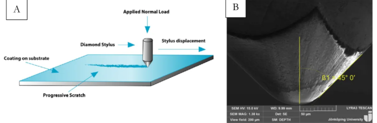
Scratch test can be used to determine surface properties and characterization of a materials hardness and surface deformation mode. Compared to abrasive wear and grinding, that by increasing action producing a large number of abrasive particles, a single-point scratch is a method to study the metal deformation process. Parameters that are of importance during the scratch process is the applied load, scratch velocity, attack angle type and hardness of indenter. Depending on the parameters and the material, the surface is influenced by the modes of material deformation, the modes are typically ductile or brittle. For metals under low load scratching conditions, ductile mode dominates as material deformation [18].
A hard scratching indenter going over a specimen surface generates a groove by dynamic surface deformation. The specimen surface experience friction between the hard indenter and the surface [18]. To determine the scratch hardness of a material, the scratch width is sufficient to analyse compared with other conventional hardness test, such as Vickers indentation, where the depth of the indent needs to be measured. Scratch testing could also yield hardness variation along a specific length of the scratch. The scratch test either produce brittle scratches or ductile scratches. The brittle scratches are characterised by material removal through fracture process and ductile scratches are mostly characterised through ploughing and deformation [18]. Figure 6 (a) is a schematic view of a low load case using nano-head module. Figure 6 (b) is a schematic view of a high load case using micro-head module.
Theoretical background Pontus Bergstedt
10
2.4.2 Reciprocating wear
Wear leads to deformation by different modes and mechanisms. The amount of removed material is defined by the wear mode, while the wear mechanism defines the deformation process. Some of the most well-studied wear modes are abrasive and adhesive wear. A wear mechanism occurs due to a thermal, chemical or mechanical nature. Example of mechanical wear mechanisms are ductile fracture, brittle fracture and plastic deformation [19]. Several mechanisms can occur simultaneously, although one is often more dominant than the others. Figure 7 illustrates relations between different terms used with wear.
Reciprocating wear is a type of sliding wear, whereas adhesion and tribo-oxidation are the main wear mechanisms. When two mating surfaces also has the presence of hard particles, abrasive wear may occur. Wear can be sectioned into three stages: run-in, steady-state and transition. In dry reciprocating sliding wear, the run-in stage is very short, as seen in Figure 8, where the asperity peaks on the mating surfaces wears down. Between the run-in stage and transition stage, the wear is in steady state. This stage has lower wear rate than the run-in stage and is controlled by a combination of tribo-oxidation and adhesion. It is the type of wear that is desirable for the lifetime of a product. The last stage is transition, as seen in Figure 8, and is characterized by the change of wear mode, typically adhesion, were the debris changes from oxidation to metallic [20].
Figure 7. Terminology for wear and their interrelations
11
2.4.2.1 Abrasive wear
Abrasive wear occurs when hard particles, either as sperate or embedded particles, scratch one or both surfaces which are sliding or moving over each other. To make a surface exhibit sufficient wear resistance, as a rule, the surface hardness must be more than half the hardness of the abrasive particle. Sufficient wear resistance is defined as following:
QR%&'()*+ > 0.5 ∗ QR),')%-.+ Equation (1) Abrasive wear resistance Maximum abrasive wear for a mechanical system, as a rule, is achieved when the surface hardness is above a factor of 1.3 times the hardness of the abrasive particles. Maximum abrasive wear resistance is defined as following;
QR%&'()*+ ≥ 1.3 ∗ QR),')%-.+ Equation (2) Maximum
abrasive wear resistance
It is important to take into account that increasing the surface hardness more than 1.3 times the hardness of the abrasive particles, will not results in wear resistance improvement [2]. Abrasive wear can be classified as Two- and Three-body abrasion, which are explained shortly as following.
Two body contact
In two-body contact abrasive wear, the particles are integrated in surface resulting in “two bodies” for that specific wear situation. Figure 9 illustrates two-body abrasive wear contact.
Three body contact
In three-body contact situation, the wear particles moves or rolls between two surfaces. Figure 10 illustrates three-body abrasive wear contact.
2.4.2.2 Adhesive wear
Adhesive wear occurs when two unsuitable materials are paired in a sliding motion under a mechanical load. Adhesion wear depends on various parameters such as material selection, applied pressure, present of lubrication as well as relative velocity of the moving surfaces. This wear mechanism has the tendency to accelerate the wear in a self-accelerating manner, evident as a wear mechanism in harsh environment for pistons. Tearing is the result of micro-welding between asperities that immediately breaks [2]. Figure 11 illustrates adhesive wear.
Figure 9. Particles integrated in the surface (Two-body-contact)
Figure 10. Particles moving between two surfaces (Three-body-contact)
Theoretical background Pontus Bergstedt
12
2.4.2.3 Tribo-Oxidative Wear
Tribo-oxidative wear is prominent during high temperature and low speed. The reciprocating wear test will lead to tribo-oxidative wear at low speed. In reciprocating sliding wear, fragments are prone to retain between the surfaces that are in contact. Figure 12 shows the different stages leading to tribo-oxidative wear. Adhesive wear leads to metallic fragments at the contacting asperities. The fragments oxidize and agglomerates onto the surface. The fragments could form scales of compact tribological layer if the load and sliding conditions are intense. The scales could make the fragments either remain in the contact region or leave the tribological system. Oxidation between contacting surfaces could lead to decrease in wear rate which is associated with change from metallic debris to oxide debris [21],[22].
2.4.2.4 Stick-slip and Sprag-slip
Sprag-slip is a phenomenon that occurs in a frictional system where one of the interacting surfaces has an angled counter force against the other, during movement relative to one another. Both surfaces experience sprag-slip when the pin moves from (3) to (4), see Figure 13.
During the turn of a reciprocating test when the direction of speed is changing, an interlocking mechanism between the two surfaces are likely to be present described by the pattern from (1) to (2), ending at (3), see Figure 13. This area is also where stick-slip is prone to happen, due to the low speed just before and after the turn and when the static friction coefficient is lower than the kinetic friction coefficient, introducing vibrations in the system, resulting in an vertical movement [23]. An illustrative way of describing the phenomenon is if the reader were to push her finger over the table, experiencing a pulsating movement.
Figure 12. 2.4.2.3 Tribo-Oxidative Wear
2
3
4 1
13
2.5 Thermophysical properties
According to ICTA, ASTM 473-85, the definition of “Thermal Analysis” is a group of different techniques where the physical property of a substance is measured as a function of temperature while the substance is subjected to a controlled temperature program.
2.5.1 Specific heat capacity
Specific heat capacity measured at constant pressure, represents the heat absorption or heat dissipation capacity of a material. The higher specific heat capacity, the higher capacity of heat absorption or dissipation a material inhibits. The thermodynamic potential enthalpy is combined with the specific heat. If the specific heat is known as a function of temperature, the enthalpy can be determined by integration.
Differential scanning calorimetry (DSC) is one of the most commonly used thermal analysis techniques to measures heat flow and temperatures related with exothermic and endothermic transitions. DSC measures the progress of a chemical and physical process occurring over a range of temperatures. Calorimetry measures the energy that is necessary to reach a zero-temperature difference between substance and the reference material subject to temperature change as each sample is subjected to an equal temperature program. The weight of the substance to be measured will show different characterization depending on the mass. With the focus on phase transformation a smaller mass will provide a more accurate representation.
The difference in heat flow between the known sample and the unknown is related to the ordinate value at any time or temperature, this is related to the kinetics of the process.
The specific heat capacity is calculated with the following formula, referencing to a sample with known properties.
;"!"#$%& =;"'&(∗ %/+(∗ ∆(/+( %0)1"2+∗ ∆(0)1"2+
Equation (3) Specific heat capacity
Where ;"!"#$%& is the unknown specific heat of the material being investigated, ;"'&(the known specific
heat of the reference material, %0)1"2+the mass of the tested sample and %/+( the mass of the reference material. The maximum temperature increased by laser irradiation, denoted by ∆(0)1"2+ and ∆(/+( for the sample and reference material, respectively [9].
Theoretical background Pontus Bergstedt
14
2.5.2 Thermal diffusivity
The laser pulse method, or laser flash analysis (LFA) is one of the most well-known and widely applied methods to measure thermal diffusivity. The front surface of a small disk sample is irradiated by a uniform pulse laser and the temperature rise curve of the back face of the sample can be used to evaluate the thermal diffusivity of the specimen. Prior the test a graphite coating is applied onto the two surfaces of the sample, to ensure efficient absorption of energy from the laser pulse.
The thermal diffusivity can be calculated through the following equation, where #3/! is a unitless constant: 1.37, P [%%] is the thickness of the sample and 43/! [9] is the half time of the maximum temperature rise for the back face.
8 = (#3/!/e!)(P!/4 3/!)
Equation (4) Specific heat capacity
Due to various assumptions, such as heat loss or that the material is homogeneous, this formula may be deficient. If so, other calculation models could be used, applying the relatively complex Cowan method could result in more accuracy [24], [25].
Two layered method
Two layered method is applicable for measuring thermal diffusivity of a substance containing two distinctive layers of different thermal properties. The diffusivity of the unknown layer is calculated from the temperature increase at the rear side together with the known specific heat, density and diffusivity of the known layer. Heat transfer between the different layers is decisively influenced by the heat resistance between the layers. The heat contact conductivity fixes decisively the temperature distribution and the efficiency of the heat transfer between the layers.
2.5.3 Thermal expansion
During thermal stresses a material will undergo dimensional changes, the expansion or contraction of this sample can be detected by a thermal expansion detection device where the physical property of a substance is measured as a function of temperature while the substance is subjected to a controlled temperature program. The coefficient of linear thermal expansion (CTE) and density (@) of the studied substance with respect to the change of temperature can then be calculated by Equation (5) Equation (6), respectively. By identifying the CTE for eligible temperatures the density subjected to temperature can be calculated using Equation (6).
;(X =ΔP P5∗
1 Δ(
Equation (5)Coefficient of thermal
expansion
@(() = @5
(1 + ;(X ∗ Δ()#
Equation (6) Density subject to
temperature
2.5.3.1 Determination of density - Archimedes principle
The Archimedes principle relies on the measurable buoyance force, that acts vertically against the gravity, that occurs when a body is immersed into a fluid and is equal to the weight force of the displaced fluid. Thus, if the weight of the sample in air, in water and the density of the fluid are known, the density of the sample can be calculated with the following Equation (7).
@5= %=)-'
%=)-'− %=6)7+'∗ @(2&-8
15
2.5.4 Thermal conductivity
Thermal conduction is a phenomenon where heat transports from high to low temperature in a substance. Thermal conductivity represents the ability to transfer heat in a material [5]. Thermal diffusivity, specific heat capacity and thermal expansion are the three main thermal properties, whereas thermal conductivity is the product of the three. The thermal analysis is of importance in this study due to the industrial perspective and for comparison between the different coatings. Figure 14 shows the thermal conductivity in room temperature for different raw materials and alloys.
It is evident that the thermal conductivity for the raw materials is significantly higher than for their alloys, as shown in Figure 14. Thermal conductivity is usually referred as λ[mm2*s-1], where λ e is the free electrons
moving in a crystal structure, electron thermal conductivity. λ p are the phonons vibrating at lattice positions,
phonon thermal conductivity. The total thermal conductivity, λ expressed as Equation (8).
λ = λ++ λ" Equation (8) Electron and phonons thermal conductivity
λ e is dominant for pure metals and λ p is significant for alloys. Metals have generally good thermal
conductivity due to the large number of free electrons. For this reason, the thermal conductivity in alloys is reduced. The impurity atoms in an alloy lowers the efficiency of the free electrons, leading to a decrease in thermal conductivity.
The total thermal conductivity is the product of thermal diffusivity, density and specific heat capacity, as seen in Equation (9) [9].
! = 8 ∗ ;"∗ @ Equation (9) Total thermal conductivity
The thermal properties are calculated as a function of temperature, making the thermal conductivity itself a function the other properties. Thermal conductivity is a commonly used indication of how the material behaves and responds to the thermal stresses.
0 50 100 150 200 250
Al EN 46000 Raw Al Raw Mg AE44
Th er m al c on du c; vi ty [W *m -1K -1]
Thermal conduc.vity for different materials
Method and implementation Pontus Bergstedt
16
3 Method and implementation
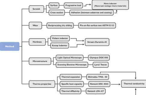
Figure 15 shows a tree map for the chapter method and implementation. Microstructure, hardness, adhesion, progressive scratch and tribological wear experiments were conducted resulting in a comparison between the coatings. The following chapter describes the different experiments, parameters and preparation respectively.
3.1 Sample preparation
To prepare the substrate material that was to be coated, material originated from HPDC biscuits were machined by 600 Lathes M390 to the dimension: Ø 50 mm, t 10 mm, as shown in Figure 16 B). The prepared samples were sent to a coating supplier abroad, applying the surface treatment trough a functional coating. In total 120 samples were prepared.
Thecoated samples that were intended for ASTM G133 reciprocating pin-on-flat surface test was further prepared by machining them in the machine Buehler ISOMET 4000 Cutter. The samples were machined in the dimensions; 35 x 35 mm. Lamellar graphite iron (LGI) pins acted as counterpart surface in the reciprocating wear test, produced accordingly to the ASTM G133 standard with the dimensions;
Ø 9 mm, l 28 mm, tip radius 4,76 mm. Bomar band saw was used to machine the
raw material into smaller pieces. As the next step to create the cylindrical parts by utilizing 600 Lathes M390 and the automatic HAAS CNC ST 10 was then used to machine the pin tip radius, 10 pins were created in total. The procedure is illustrated in Figure 17 A) and B) for the samples and pins respectively.
Figure 15. Tree representation of method chapter
Figure 16. A) HPDC biscuit & ingate B) HPDC biscuit before & after machining
A
B
Figure 17. A) Machined biscuit for reciprocating dry sliding wear test B) Preparation of LGI pins for pin on disc
17
Sample preparation for the thermophysical experiments required specific dimensions depending on the different tests. Netzsch LFA 427 used for the thermal diffusivity test required dimensions of Ø 10 mm, t ~ 4 mm. The thermal expansion machine Shimadzu TMA-50 required dimensions of Ø 5 mm, t ~ 2 mm, whereas the flatness of the surfaces was of importance. Netzsch DSC 404 C utilized for the specific heat capacity required dimensions of Ø 5 mm, weight ~42.1mg. These samples were obtained by operation of an automatic mill. The small samples were then cut into the final sizes in the high speed cutter, Buehler ISOMET 4000 Cutter. Figure 18 shows the preparation stages for the thermophysical experiments.
To prevent unwanted reactions induced by machining, a protective lacquer from Struers was applied. Ultrasonic cleaner was used with the dissolvent medium acetone for 3 hours, the samples were weighted and measured before and after to confirm that the applied lacquer was removed.
An adapter was mounted onto the coated samples prior to the scratch testing. To mount the adapter, a glue with capillary effect was used.
3.2 Polishing of samples
Some tests and analyses require hot mounted resin specimen, cured in Struers CitoPress-1 using the resin powder PolyFast by Struers to reassure the compatibility with the electron microscope. The samples were polished in Struers Tegramin-30 with different stages, as shown in Table 1. Between the different stages, both the sample holder and the samples were washed in Struers Lavamin, reducing the risk of contamination.
Table 1. Polishing stages
Stage Force [N] Durance [min] Polishing disc Lubricant
1 20 1 MD Piano 80K Water
2 20 2 MD Piano 120K Water
3 15 5 MD Largo 9 µm DiaPro Allegro/Largo 9 µm
4 15 2 MD Mol 3 µm DiaPro Mol 3 µm
5 10 1.5 MD Mol 1 µm DiaPro Mol 1 µm
6 10 1.5 MD Chemo OP-S NonDry
Method and implementation Pontus Bergstedt
18
3.3 Analysis using microscope
A light optical microscope, Olympus DSX1000, was used to study the microstructure of the polished samples and for analysing the results from other tests. The microscope has an image analysis software that is used to analyse the microstructure and can also make 3D images by stacking images. The samples were placed in the microscope and magnification from 3x-50x magnification was used to analyse the surfaces as a result of different test. A scanning electron microscope (SEM), Lyra3 Tescan, was used to analyse the microstructure, wear tracks and scratches at higher magnification. Energy-dispersive X-ray spectroscopy (EDS) was also used in conjunction with the SEM to analyse the composition of the materials, the microscopes are shown in Figure 19.
3.4 Hardness test
To measure the hardness of the coatings and the substrate, hardness indentation was conducted with both Vickers and Knoop hardness test using Struers Duramin-40. The tests were carried out in room temperature with load of 50gr and 100gr and dwelled for 10 seconds at different positions to acquire a mean value.
3.5 Adhesion
To measure the adhesion between the substrate and the coating the micro and nano-scratch machine developed by Micro-materials NanoTest system was used. The samples were placed in the holder and constant load was applied while the holder moved in z-axis. The scratch length was 350 µm with different load cases from 500 mN up to 2700 mN. Five adhesion tests were conducted on each sample utilizing the high load nano indenter modelled as a sphero-conical diamond with a tip radius of 50 µm with induced cone angle of 2β = 90 ° was used to conduct the micro-scratch testing, seen in Figure 20 B).
3.6 Progressive scratch experiment
Scratch resistance of the different coatings was characterised by a single-pass scratch test using a micro and nano-scratch machine developed by Micro-materials NanoTest system. The machine has a microscope, tangential friction force and penetration depth sensors. The sample is fixed in a holder on a positioning table that moves in z-axis up and down. During the movement, the contact load can either be constant or progressive at a user-defined rate. In the thesis the progressive load is analysed. During the scratch, the depth penetration and friction force are recorded. Figure 20 A) illustrates the scratch test.
A B
19
The same indenter that was utilized during the adhesion test was used during the progressive scratch experiment. The tests were performed under different loads ranging from 500 mN to 2000 mN. The scratches were 1000 µm in length with a scratch speed of 20 µms-1 in room temperature ~ 25°C. Before and
after each scratch, topography of the surface was conducted with a profiling load of 0.1 mN. After the scratch test, the width was measured at different locations for each scratch and analysis in light- and electron microscope was conducted.
3.7 Reciprocating dry sliding wear experiment
To perform the reciprocating dry sliding wear test the ASTM G133 standard was used. The standard covers the laboratory procedures to determine the sliding wear and friction properties. The geometry for the standard is a linear, oscillating ball-on-flat surface geometry.
A load is constantly applying a vertical force against a roller. The roller pushes the specimens, the pin and the flat surface, together with an equal force making the surfaces of the specimens always being forced against each other as they oscillate. The specimens reciprocate periodically relative to each other. The test was executed in a dry state, room temperature with relative humidity of 40 – 60%. Figure 21 shows the machine that was used for the test and the illustration from the ASTM G133 standard.
Figure 21. Reciprocating dry sliding wear machine Figure 20. A) Schematic view of progressive load B) Indenter
Method and implementation Pontus Bergstedt
20
The samples were prepared in the form of squares with the dimension 35 x 35 mm as Figure 22 shows. The optimized geometry generated the possibility of 8 individual wear tracks to be inflicted to each surface. The reciprocating pins were designed for the possibility to be reshaped, creating a new surface to be used up to 3 times. For each wear test, the pin and track were documented, making it possible to corelate the two surfaces and tackle each wear test case in the aspect of weight and visual appearance, to be able to characterise the wear mode.
A cryogenic load cell indicated that the tests were performed with the intendent load of 25 N between the two surfaces. The load was calibrated before every test. The test run for 120, 240, 360, 480 and 1000 seconds were conducted with the same parameters, onto the 3 different coatings for the possibility of a representative evaluation and comparison.
Mass loss rate was acquired for the wear track and the corresponding reciprocating pin through weight measurements obtained through a scale with 0.0001 mg accuracy. It was crucial to document the starting mass of each wear test case prior the new test run, the sample and pin was cleaned in ultrasonic cleaner in acetone for 6 minutes, corresponding to the ASTM standard before the measurements, see (1) Figure 23. After the reciprocating wear test, the wear track and pin were photographed and weighted, see (2) Figure 23. Thereafter cleaned in the ultrasonic cleaner in acetone for 6 minutes, removing the debris, and the coated sample and pin was weighted once again, see (3) Figure 23. This procedure made it possible to conclude the variation of mass for the system prior and after the induced wear test, evaluate the produced debris and understand how the wear system behaved. Utilizing an advanced light optical microscope to quickly estimate the damage of the wear track served as a fundamental evaluation where the decision of parameters for the next test run could be made.
C797 6
%= 1
C(
Figure 22. Illustration of sample before and after preparing for wear test
1
2
3
21
3.8 Thermophysical properties
Thermal conductivity is the product of thermal diffusivity, density and specific heat capacity. The different tests were therefore conducted in the same argon atmosphere and temperature interval. Figure 24 represents the method used to calculate thermal conductivity.
3.8.1 Thermal expansion
The thermal expansion is one of three thermal properties that is to be acquired in order to calculate the thermal conductivity. The expansion was measured with the use of the test equipment: Shimadzu TMA-50, see Figure 25, with a temperature range from 25 – 400°C, with a constant temperature velocity of 5°C*min-1.
When hypotheses regarding elevated temperature resulting in irreversible material property changes, some of the samples also was tested during cooldown. Due to the heating of the sample, the tests were conducted in an argon atmosphere preventing eventual reactions with oxygen.
The geometry of the specimen was prepared, with a focus on the vital parameter: ensuring two flat, parallel surfaces through the sample which the measurement was recorded. With the assumption of an isotropic material, the measurement in one dimension would be accepted as a representative thermal expansion of the investigated material in any direction. The expansion in three dimensions is therefore considered to be elevated by three, and larger than for that in one dimension.
3.8.1.1 Density Archimedes principle
The actual parameter needed to calculate the thermal conductivity is not the expansion, the density is the relevant one. Generally, when a material is heated the density will decrease, the mass will remain the same whilst the specimen expands, this corelation makes it possible to indirect measure the density change subjected to temperature change using the coefficient of thermal expansion. In order to use the formula, Equation (7) Density in RT, the initial condition of the density
and thickness in room temperature was measured. A modified scale, relying on the Archimedes principle was used to determine the density, see Figure 26.
Figure 24. Tree representation of thermal properties
Figure 25. Shimadzu TMA - 50, thermal
Method and implementation Pontus Bergstedt
22
3.8.2 Specific heat capacity
The differential scanning calorimetry (DSC) method calculates the specific heat capacity. The machine used in the experiments is the Netzsch DSC 404 C, see Figure 27.
The machine has a measuring head with two crucibles within the furnace, one for the unknown substance and one for the known reference material, connected to a thermocouple each. The thermocouples are wired to measure the temperature difference between the sample and the reference material. In the experiments, the reference material used was sapphire. The weight of the sapphire should correspond to the weight of the sample. The sapphire samples have the following weights: 20.8 mg, 42.1 mg, 64.2 mg, 83.9 mg. The experiments were conducted in argon atmosphere and the temperature range was between 25 - 400°C using the 42.1 mg sapphire reference sample.
The absolute temperature is measured with the reference thermocouple. The crucibles are identical due to the dependency of material and size for the substance to be measured and the temperature range of interest. To determine the specific heat capacity, three measurements were considered: correction, standard and sample. During the correction measurement both crucibles are empty. The measurement is performed as a correction for thermal gradients in the furnace.
3.8.3 Thermal diffusivity
In the Netzsch laser flash method (Netzsch LFA 427), see Figure 28, a laser beam is absorbed in a thin layer at the front of the test piece. The temperature distribution inside the unknown sample depends only on the thermal diffusivity of the material. The experimental situation is strongly influenced by the initial and boundary conditions. Some of these conditions are; heat losses that are frequently significant and particularly at higher temperatures, layered materials and inhomogeneous materials.
The calculation method that was used during the thermal
diffusivity test was Cowan + pulse correction. The adiabatic method is a simplified calculation were the utilization of Cowan + pulse correction includes heat loss in the computational equation.
3.8.4 Thermal conductivity
The thermal conductivity is as earlier mentioned, calculated by the product of specific heat capacity, density and thermal diffusivity. The specific heat capacity and thermal diffusivity data was collected from the measurements. The density is calculated with the coefficient of linear thermal expansion (CTE) derived from the thermal expansion measurements. The measurements were collected in a database where the Cp, α and ρ was calculated for different temperatures. For each experiment, samples were tested twice. This resulted in two different set of data that was used to calculate the thermal conductivity.
Figure 27. Netzsch DSC - 404 C, specific heat capacity
23
4 Findings and analysis
The following chapter presents findings and analyses resulting from the thermophysical and tribological experiments conducted in the present thesis, together with fundamental experiments supporting the main investigations.
4.1.1 Al EN46000 – as-cast and coated
It has been discussed and elaborated in many studies that the microstructure has a vital influence on the thermal, mechanical, as well as tribological properties of aluminium and magnesium alloys. Hence, the microstructure analysis was performed and the results presented accordingly in this section describes the difference in microstructures for Al EN46000 biscuit and ingate samples. In addition, it is worth mentioning that in HPDC alloys, to consider the origin of the selected samples, due to the variation between the samples taken from biscuits and ingate system which could influence the results considerably. Additionally, the microstructure of the three different coatings applied on the aluminium samples were investigated. Figure 29 A) shows the microstructure of the investigated Al EN46000 originated from the biscuit consisting of primary aluminium (α) in the form of dendrites and refined Al-Si eutectic phases due to addition of strontium. Arrow 1) in Figure 29 A) indicates the primary α phase and arrow 2) shows the eutectic phases. Arrow 3) in Figure 29 A), indicates intermetallics found in the matrix. The Al EN46000 microstructure from the biscuits varies from the one originating from the cast product. Figure 29 B) shows the microstruture of the cast product. The microstructure of the cast product consist of dendritic α-Al phases with eutectic phases modified by strontium. Figure 29 B) arrow 4) shows the α-Al phases and arrow 5) shows the eutectic phases modified by strontium. Figure 29 B) arrow 6) shows sludge particles originated from the casting process.
The difference between the microstructure for the biscuit and cast product results in variations in thermophysical and mechanical properties. The thermal conductivity is dependent on the free path of electrons in the alloy. The eutectic Si phases are of high resistance, hindering the electrons to transport through the alloy. This results in a decrease for thermal conductivity in these regions. The eutectic phases modified with Sr are evident to increase the thermal conductivity, being the majority of the cast products eutectic phase, this is the reason why thermal conductivity is higher for the ingate than for the biscuit sample. Stress concentrations at the grain boundaries could lead to promotion of debris generation, leading to increased wear rate.
A
B
Figure 29. A) Microstructure from biscuit B) Microstructure from ingate