AN ADVANCED PLATFORM FOR DEVELOPMENT AND EVALUATION OF GRID INTERCONNECTION SYSTEMS USING HARDWARE-IN-THE-LOOP
by
© Copyright by Blake R. Lundstrom, 2013 All Rights Reserved
A thesis submitted to the Faculty and the Board of Trustees of the Colorado School of Mines in partial fulfillment of the requirements for the degree of Master of Science (Electrical Engineering). Golden, Colorado Date Signed: Blake R. Lundstrom Signed: Dr. Pankaj K. Sen Thesis Advisor Golden, Colorado Date Signed: Dr. Randy Haupt Professor and Head Department of Electrical Engineering and Computer Science
ABSTRACT
The recently highlighted vulnerabilities, environmental effects, and critically aging status of the North American Electric Power System (EPS) are fueling a shift towards a power system paradigm that more fully leverages Distributed Resources (DRs). In order to support and accelerate DR grid integration, methods to rapidly evaluate DRs against existing grid interconnection standards and assess advanced DRs integrated in complex EPS scenarios are needed. This thesis develops a novel solution for rapid evaluation of DR grid interconnection standard conformance that uses a real-time simulator and a single graphical user interface to automate the time-consuming process required for the many repeated conformance tests of IEEE Std 1547.1™. A method for evaluating advanced DR grid integration scenarios using Power Hardware-in-the-Loop (PHIL) is presented. The results from a novel demonstration of a DR grid integration scenario using both PHIL-based and hardware-only approaches are presented, establishing the utility and validity of the PHIL method.
TABLE OF CONTENTS
ABSTRACT . . . iii
LIST OF FIGURES . . . ix
LIST OF TABLES . . . xii
LIST OF ABBREVIATIONS . . . xiii
ACKNOWLEDGMENTS . . . xv
CHAPTER 1 INTRODUCTION . . . 1
1.1 The Existing Power System Paradigm . . . 1
1.2 Towards a New Power System Paradigm with Distributed Resources . . . 4
1.3 The Role of Grid Codes and Standards and the Need for Advanced Evaluation Methods . . . 7
1.4 Problem Statement . . . 8
CHAPTER 2 GRID INTERCONNECTION AND THE ROLE OF IEEE STD 1547 IN THE UNITED STATES . . . 9
2.1 The IEEE 1547 Series of Interconnection Standards . . . 10
2.2 IEEE Std 1547 . . . 12
2.2.1 Requirements . . . 12
2.2.2 Gaps . . . 16
2.2.3 Applicability of IEEE Std 1547 and Relation to UL 1741 and Other Standards . . . 18
2.3 IEEE Std 1547.1 . . . 19
2.3.2 Abnormal Frequency Tests . . . 21 2.3.3 Unintentional Islanding . . . 22 2.4 IEEE Std 1547.2 . . . 23 2.5 IEEE Std 1547.3 . . . 24 2.6 IEEE Std 1547.4 . . . 25 2.7 IEEE P1547.5 . . . 26 2.8 IEEE Std 1547.6 . . . 26 2.9 IEEE P1547.7 . . . 27 2.10 IEEE P1547.8 . . . 27
CHAPTER 3 HARDWARE-IN-THE-LOOP SIMULATION TECHNIQUES . . . 28
3.1 Basics and Terminology . . . 28
3.2 Types of HIL Testing . . . 31
3.2.1 Real-time Simulator (RTS)-based Simulation Only . . . 31
3.2.2 RTS as Device Under Test (DUT) Controller . . . 32
3.2.3 Controller Hardware-in-the-Loop (CHIL) . . . 34
3.2.4 Power Hardware-in-the-Loop (PHIL) . . . 36
3.2.4.1 Basics . . . 36
3.2.4.2 Implementation Challenges . . . 39
3.2.4.3 Literature Summary . . . 46
CHAPTER 4 METHOD FOR RAPID EVALUATION OF GRID INTERCONNECTION SYSTEM CONFORMANCE TO IEEE STD 1547 . . . 47
4.1 Problem Statement . . . 48
4.3 Methodology . . . 50
4.4 Realization . . . 50
4.4.1 Electrical Hardware Setup . . . 52
4.4.2 RTS and Models . . . 53
4.4.2.1 Real-time Simulator (RTS) . . . 53
4.4.2.2 Voltage Source Model . . . 53
4.4.2.3 Load Model . . . 54
4.4.2.4 DC Source or PV Simulator Model . . . 55
4.4.2.5 Abnormal Grid Condition Model . . . 56
4.4.3 Results Analyzer and Plotter . . . 56
4.4.4 Graphical User Interface . . . 59
4.4.5 GISE Test Configuration and Sequence . . . 62
4.5 Results . . . 64 4.5.1 OV Tests . . . 66 4.5.1.1 Time . . . 66 4.5.1.2 Magnitude . . . 66 4.5.2 UV Tests . . . 69 4.5.2.1 Time . . . 69 4.5.2.2 Magnitude . . . 71 4.5.3 OF Tests . . . 73 4.5.3.1 Time . . . 73 4.5.3.2 Magnitude . . . 75 4.5.4 UF Tests . . . 75
4.5.4.1 Time . . . 78
4.5.4.2 Magnitude . . . 78
4.5.5 Unintentional Islanding . . . 80
4.6 Conclusions . . . 84
CHAPTER 5 DEVELOPMENT OF A PLATFORM FOR ADVANCED DISTRIBUTED RESOURCE GRID INTERCONNECTION STUDIES . 85 5.1 Problem Statement . . . 86 5.2 Literature Review . . . 87 5.3 Solution Methodology . . . 89 5.4 Modeling . . . 93 5.4.1 Power Amplifier . . . 93 5.4.2 Fixed RLC . . . 98 5.4.3 Variable RLC . . . 98
5.4.4 Stabilization of Real-Time Model . . . 101
5.5 Test Methodology and Hardware Setup . . . 101
5.5.1 Task 1: Demonstrate Validity of PHIL Technique . . . 103
5.5.2 Task 2: Demonstrate Advanced Applications of PHIL . . . 104
5.6 Key Results - Task 1 . . . 106
5.7 Key Results - Task 2 . . . 112
5.8 Conclusions / Applications . . . 116
CHAPTER 6 CONCLUSION . . . 118
6.1 Application . . . 118
6.3 Contribution . . . 120
REFERENCES CITED . . . 121
APPENDIX A - COPYRIGHT PERMISSION LETTER . . . 130
LIST OF FIGURES
Figure 2.1 Illustration of where various interconnection-related codes and
standards apply . . . 19
Figure 2.2 Representation of trip magnitude test function (Based on Figure A.2 of IEEE Std 1547.1 ) . . . 21
Figure 2.3 Graphical representation of trip time test function (Based on Figure A.3 of IEEE Std 1547.1 ) . . . 22
Figure 2.4 Unintentional islanding test circuit (Simplified version of Figure 2 of IEEE Std 1547.1 ) . . . 24
Figure 3.1 Typical HIL Simulation Architecture . . . 28
Figure 3.2 Example of using the RTS as Controller HIL simulation technique . . . . 33
Figure 3.3 An implementation of CHIL for evaluation of a hardware-based PV inverter controller . . . 35
Figure 3.4 An implementation of PHIL for evaluation of a PV inverter . . . 38
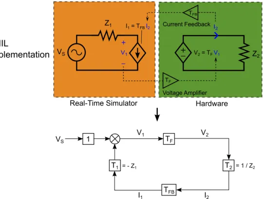
Figure 3.5 The implementation of a voltage divider using PHIL . . . 40
Figure 3.6 Control system block diagram for the PHIL voltage divider . . . 41
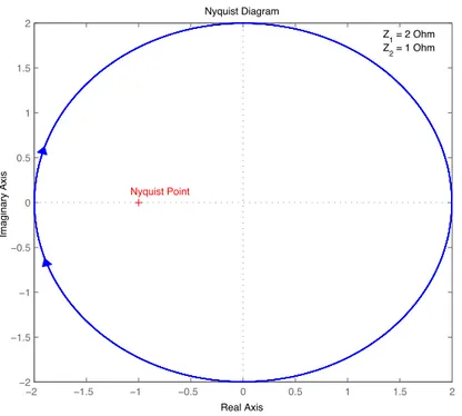
Figure 3.7 Nyquist plot of GL for Z1 = 2 Ω and Z2 = 1 Ω . . . 44
Figure 4.1 Grid Interconnection System Evaluator (GISE) architecture . . . 51
Figure 4.2 Voltage source model . . . 54
Figure 4.3 PV simulator architecture . . . 57
Figure 4.4 Abnormal grid condition model . . . 58
Figure 4.5 Example summary test report for an undervoltage time/step test . . . 60
Figure 4.7 Test configuration and status portion of the GUI . . . 65
Figure 4.8 Multiple overvoltage time test runs . . . 68
Figure 4.9 Multiple overvoltage magnitude test runs . . . 70
Figure 4.10 Multiple undervoltage time test runs . . . 72
Figure 4.11 Multiple undervoltage magnitude test runs . . . 74
Figure 4.12 Multiple overfrequency time test runs . . . 76
Figure 4.13 Multiple overfrequency magnitude test runs . . . 77
Figure 4.14 Multiple underfrequency time test runs . . . 79
Figure 4.15 Multiple underfrequency magnitude test runs . . . 81
Figure 4.16 Multiple underfrequency magnitude test runs . . . 83
Figure 5.1 An implementation of PHIL for evaluation of a PV inverter connected to the IEEE Std 1547.1 unintentional islanding circuit . . . 91
Figure 5.2 Power amplifier system identification test setup . . . 95
Figure 5.3 Output filter topology of the power amplifier . . . 97
Figure 5.4 Bode plots of the power amplifier’s measured and modeled frequency response . . . 99
Figure 5.5 Simulink implementation of a variable capacitor . . . 101
Figure 5.6 Discrete hardware realization of the unintentional islanding test with a fixed RLC load . . . 104
Figure 5.7 PHIL realization of the unintentional islanding test with a fixed RLC load . . . 105
Figure 5.8 PHIL realization of the unintentional islanding test with a variable RLC load . . . 107
Figure 5.9 Results from the task 1 unintentional islanding test for qf = 1.04 . . . . 108
Figure 5.11 Results from the task 1 unintentional islanding test for qf = 4.35 . . . . 110 Figure 5.12 Inverter current and voltage from repeated tests of the task 1
unintentional islanding test for qf = 2.84 . . . 111 Figure 5.13 Results from the task 2 unintentional islanding test for qf ∼= 1 with a
poorly-tuned RLC load (igrid1∼= 0.02 · iinv,F L) . . . 113
Figure 5.14 Results from the task 2 unintentional islanding test for qf ∼= 1 with a
well-tuned RLC load (igrid1 ∼= 0.002 · iinv,F L) . . . 114
Figure 5.15 Results from the task 2 unintentional islanding test for qf ∼= 3 with a
LIST OF TABLES
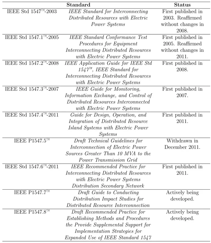
Table 2.1 Current status of IEEE 1547 series of interconnection standards . . . 11
Table 2.2 Summary of Key Interconnection Requirements and Specifications in IEEE Std 1547-2003 . . . 13
Table 3.1 Summary of PHIL interfacing methods, as introduced in . . . 43
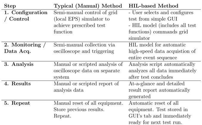
Table 4.1 Comparison of manual and RTS-based grid conformance evaluation methodologies . . . 52
Table 4.2 Summary of selected overvoltage time tests . . . 67
Table 4.3 Summary of selected overvoltage magnitude tests . . . 69
Table 4.4 Summary of selected undervoltage time tests . . . 71
Table 4.5 Summary of selected undervoltage magnitude tests . . . 73
Table 4.6 Summary of selected overfrequency time tests . . . 75
Table 4.7 Summary of selected overfrequency magnitude tests . . . 78
Table 4.8 Summary of selected underfrequency time tests . . . 80
Table 4.9 Summary of selected underfrequency magnitude tests . . . 80
LIST OF ABBREVIATIONS
AC . . . Alternating Current A/D . . . Analog to Digital CCCS . . . Current-Controlled Current Source CHIL . . . Controller Hardware-in-the-Loop CPU . . . Central Processing Unit D/A . . . Digital to Analog DG . . . Distributed Generation DR . . . Distributed Resource DSP . . . Digital Signal Processor DUT . . . Device Under Test EPS . . . Electric Power System FCF . . . Feedback Current Filtering FPGA . . . Field-Programmable Gate Array HIA . . . Hardware Inductance Addition HIL . . . Hardware-in-the-Loop ICS . . . InterConnection System ITM . . . Ideal Transformer Method LTI . . . Linear time-invariant MRP . . . Multi-rate Partitioning PCC . . . Point of Common Coupling
PHIL . . . Power Hardware-in-the-Loop PV . . . Photovoltaic RTS . . . Real-time Simulator STATCOM . . . STATic Synchronous COMpensator VCVS . . . Voltage-Controlled Voltage Source
ACKNOWLEDGMENTS
I would like to first acknowledge my advisor, Dr. P.K. Sen, and committee members, Dr. Ravel Ammerman and Dr. Benjamin Kroposki, for their advice, support, and vision throughout this effort. Without these three wonderful mentors, I would, more than likely, not have discovered and become interested in the area of renewable energy and power systems; it has been by their passion, excellent teaching, and wise advice that I have been lucky enough to learn and work in this area.
I extend my gratitude to Dr. Mariko Shirazi and Dr. Barry Mather of the National Renewable Energy Laboratory (NREL) who have both been very instrumental throughout this research effort, especially in the all-important aspects of fruitful discussions on imple-mentation ideas, reviewing my work, and debugging when things weren’t working right. I would also like to thank the rest of the Distributed Energy Systems Integration group at NREL for many helpful discussions, assistance in the lab, and mentoring.
I would like to acknowledge the financial support I have received through NREL and the U.S. Department of Energy’s Solar Energy Technologies Program.
Last, but certainly not least, I thank my family, especially my parents, brother, and my loving wife, for all of their tireless support, without which this work would not have been possible.
CHAPTER 1 INTRODUCTION
From its inception in the 1880s, the north american electric power delivery system has expanded immensely into what the U.S. National Academy of Engineering has called “the single greatest engineering achievement of the 20th century” [1]. Yet, despite such a large expansion, the power system’s basic mode of operation has changed very little; the initial concept of a central power plant generating electricity that is then distributed to a network of loads, which was demonstrated by Edison’s Pearl Street Station and its first customers in the 1880s, is largely still in use in today’s power system. Significant development of nearly every aspect of Edison’s system design occurred, yet today’s electric grid still predominantly consists of unidirectional power flow from a centralized primary generation source through three-phase Alternating Current (AC) transmission and distribution systems to a network of distributed loads. However, this power system paradigm, which worked well for over a hundred years, is experiencing new pressures.
1.1 The Existing Power System Paradigm
The goal of the electric power system has always been to deliver electricity to customers safely, reliably, and economically. Historically, the power system paradigm of centralized generation with unidirectional power flow to loads has met these criteria well enough. Cen-tralized generation has generally taken the form of large, fossil fuel-based power plants located relatively close to load centers. The large and centralized nature of power plants has encouraged a focus on the efficiency of the generation equipment itself, resulting in cheaper electricity for the end user, while maintaining a level of safety and reliability in that electric utilities can more easily control, maintain, and monitor generation assets when in fewer cen-tralized locations. Fossil fuels, such as coal and natural gas, have historically been readily available and cheap and thus the economical choice for large power plants. The location
of power plants relatively close to load centers results in more efficient, and thus more eco-nomical, distribution of electricity from the power plant to the majority of customers. The goal to deliver electricity in a manner that is characteristically safe, reliable, and economical remains the same today; however, as these characteristics are taking on new meanings in light of recent events and new pressures, the traditional power system paradigm is beginning to change towards the greater use of distributed and renewable generation assets.
What it means to deliver electric power safely has changed; the safe delivery of electric power, which used to relate principally to generating and distributing power so that it could be utilized by customers without any personnel injury or property damage from the electricity itself, now applies also to the security of the energy supply and physical grid infrastructure as well as the longer-term environmental impacts that directly affect mankind’s well being. While the vulnerability of centralized generation to terrorist attacks and natural disasters has always been present, events such as the 2007 demonstration by a team of hackers at Idaho National Laboratory of how a generation asset can be destroyed [2], a 2008 revelation by CIA officials that hackers had shut off the power supply to several unnamed cities outside the U.S. [2], the devastating and lasting effects of a 2011 natural disaster on Japan’s Fukushima nuclear power plant [3], and the multi-billion dollar damage [4] of Hurricane Sandy in 2012 have highlighted the issue. Recent reports, such as the U.S. National Academy of Sciences’ Terrorism and the Electric Power Delivery System [5], continue to emphasize the physical, cyber, and personnel vulnerabilities, which are exacerbated by the use of centralized generation, of the electric power delivery system.
The longer-term environmental impacts of burning fossil fuels, the primary fuel source for large centralized power plants, has also been highlighted as a more important public safety issue in recent history. At the core of the most recent attention to this issue has been the discussion of global climate change and its effects. A number of national and international scientific bodies [6, 7, 8, 9, 10, 11] concur with the Intergovernmental Panel on Climate Change (IPCC)’s position that “warming of the climate system is unequivocal, as
is now evident from observations of increases in global average air and ocean temperatures, widespread melting of snow and ice and rising global average sea level” [12]. The majority of these scientific bodies also agree with the IPCC’s position that “most of the warming observed over the last 50 years in attributable to human activities” [13] such as the burning of fossil fuels. However, regardless of one’s opinion on the cause of climate change or even whether it is significant across the longer span of geological time, it is irrefutable that climate change has occurred over the last 50 years and thus the effects, short term and long term, of climate change should be considered. The IPCC, many of the international scientific bodies referenced above, and a number of health organizations [14, 15, 16] indicate that, among other consequences of climate change, public safety and well-being is threatened; incidents of injury or death caused by extreme weather events and natural disasters, climate-sensitive infectious diseases, and air pollution-related illness are increasing. Thus, it is clear that the recent threats to the security of the energy supply and physical grid infrastructure, as well as the longer-term environmental impacts that directly affect mankind’s well-being, have made safe delivery of electric power more difficult than ever. This brings into question the traditional exclusive use of large, centralized, fossil fuel-based generation.
The continued reliable and economic delivery of electric power has also been brought into question recently. A 2009 U.S. Department of Energy (DOE) report [1] emphasizes that “there have been five massive blackouts over the past 40 years, three of which have occurred in the past nine years,” and that these outages and other interruptions “cost Americans at least $150 billion each year” [1]. While “today’s electricity system is 99.97 percent re-liable” [1], a very impressive figure, the system is “aging, inefficient, and congested, and incapable of meeting the future energy needs of the Information Economy without opera-tional changes and substantial capital investment over the next several decades” [17]. The electric power delivery system has reached this state largely because it matured in an era when the consumer’s electricity bill was the most important factor; energy efficiency, envi-ronmental impacts, and customer choice were minor concerns [17]. This has meant that,
despite sustained growth for nearly the entire 20th century, capital investment was kept very low such that only the minimum transmission and distribution networks were built; upgrades of key equipment were often made only upon failure; large, centralized, fossil fuel-based gen-eration was favored; wholesale markets were limited; and control and metering functions were limited. However, as the full costs, both short-term and long-term, of fossil fuels, less efficient generation and distribution architectures, and difficult infrastructure upgrades are beginning to be considered, it is becoming clear that the historical power system paradigm is unsustainable.
1.2 Towards a New Power System Paradigm with Distributed Resources A new advanced power system paradigm, often referred to as smart grid, that addresses many of the issues of the existing electric power delivery system is needed. According to the U.S. DOE, the key characteristics of an ideal advanced power system paradigm are that it “enables active participation by consumers; accommodates all generation and storage op-tions; enables new products, services, and markets; provides power quality for the digital economy; optimizes assets and operates efficiently; anticipates and responds to system dis-turbances (self-heals); and operates resiliently against attack and natural disaster” [1]. By adapting these characteristics, the power system of the future would be able to deliver elec-tricity safely, reliably, and economically while being more resilient to attacks and natural disasters, utilizing environmentally responsible energy sources, more efficiently using exist-ing transmission and distribution systems, and makexist-ing future grid infrastructure upgrades much more feasible. As indicated in a recent DOE report [17], a number of key technolo-gies can help enable this power system paradigm shift: “advanced conductors made from new composite materials and high temperature superconducting materials, advanced electric storage systems such as flow batteries or flywheels, distributed intelligence and smart con-trols, power electronics devices for AC-DC conversion and other purposes, and distributed energy resources including on-site generation and demand management” [17].
Out of these technologies, distributed energy resources, often referred to as simply Distributed Resources (DRs), are one of the most effective as their use directly addresses a majority of the existing power system’s issues. As the name suggests, DRs are small-scale (the IEEE 1547 standard indicates < 10 MVA [18]) power generation, sometimes referred to as Distributed Generation (DG), or energy storage technologies located close to the load being served and can be powered by a variety of energy sources including renewable sources such as Photovoltaic (PV) and wind. The dispersed nature of DRs allow for greater safety and secu-rity as the overall power system is less vulnerable to a single attack or natural disaster and greater energy independence and reliability can be achieved as dispersed DRs can be sepa-rated from the grid to support local loads in the event of a wide area outage. DRs are often powered by renewable sources such as PV or wind, which are much more environmentally friendly than fossil fuels. Because DRs are most often located close to the load being served, the need for distribution and transmission systems that are expensive to build, maintain, and operate is greatly reduced; also, overall efficiency is improved as less power losses occur because power travels much shorter distances than when sourced from centralized generation assets. The ability to provide “ancillary services such as voltage support or stability, VARs, contingency reserves, and black start capability” [19] is an important capability that is most valuable to the local Electric Power System (EPS). Furthermore, DR-based generation offers “greater economies from mass-production than big ones [can] gain through unit size. The increased value—due to improvements in financial risk, engineering flexibility, security, and environmental quality—of these resources can often more than offset their apparent cost disadvantages” [20].
The use of renewable energy-based generation, which is often in the form of DRs, con-tinues to increase rapidly. Worldwide, 71 countries have renewable portfolio standards or other quotas mandating that their electric utilities produce a portion of their electricity from renewable sources [21]. The effect of these quotas is evident; investments in new renewable power capacity worldwide have increased over 150% and worldwide installed solar PV
capac-ity has increased by more than 300% from 2009 to 2011 alone [21]. The U.S. DOE’s Energy Information Administration predicts that this trend of growing renewable power capacity will continue for the foreseeable future, at least through 2035 [22].
The use of DRs, especially those powered by renewable sources with inherent variability, comes with its own set of challenges. A 2008 Renewable Systems Interconnection study, commissioned by the National Renewable Energy Laboratory, identifies the key technical concerns as: voltage and VAR regulation, power quality, unintentional islanding, protec-tion design and coordinaprotec-tion, and equipment grounding [23, 24]. As suggested in [25], the magnitude of these concerns is dependent on many factors including:
• Local, and sometimes regional, EPS architecture including its electrical characteristics (system impedance, location in the larger system, nearby equipment (voltage regu-lation, loads, etc.), grounding design, etc.) and control, operation, and protection schemes
• Type of energy resource (PV, wind, etc.) used and its dispatchability
• Characteristics, including converter type, rating, impedance, transformer, grounding, and implemented control functionalities, of the grid InterConnection System (ICS), which interfaces between the energy resource and the EPS
• Local proliferation of other DRs
However, much progress, as described in [26], towards addressing these issues has been made, which has aided the rapid installation of DRs, especially those that are PVs-based, as demonstrated in a number of case studies in [26] and, most notably, in a recent report that “during some hours of 2012, PV already contributed about 40% of the peak power demand” for all of Germany [27].
1.3 The Role of Grid Codes and Standards and the Need for Advanced Evalu-ation Methods
With the increasing proliferation of DRs and the integration challenges that accompany them, it is essential that DR installations occur in a manner that does not stress, but rather strengthens the EPS. To this end, grid codes and standards have been developed and implemented in many countries worldwide. Summaries of many of these key grid codes, including those implemented in Germany, Italy, the United States, Japan, Belgium, and Australia, are discussed in [26]. Though exact implementations certainly vary, grid codes generally address how DRs provide power to the EPS and how they must respond in abnormal grid voltage, frequency, or disconnection (islanding) scenarios. Some grid codes, such as those implemented in Germany, require specific active power control functions and the option for control of reactive power by the local EPS operator, while others, such as those in the United States, Italy, Belgium, and Australia, have little or no active or reactive power control regulations. However, all of these countries are actively developing newer grid code revisions to update codes that were designed around low penetrations of DRs to include important control functionalities required to support an advanced EPS architecture.
Grid codes and standards go a long way towards ensuring that DRs strengthen and not stress the local EPS, however they will never be sufficient for all installations and situations. The vast diversity of the EPS–with all its various potential interconnection points, different DR and traditional generation situations, operational scenarios, load requirements, and per-formance criteria– ensures that additional grid interconnection requirements will be required in certain cases. As such, the ability to easily simulate these unique local EPS scenarios in conjunction with a particular DR under consideration so as to identify the needed grid inter-connection requirements and advanced controls is very important. While compliance with existing grid codes provides a reasonable estimate of the baseline performance of a DR once interconnected with the EPS, more advanced simulation methods are crucial for complete understanding of how a DR will interact with the EPS in complex scenarios that may include
abnormal grid voltage and frequency excursions, islanding, and interactions with other DRs. 1.4 Problem Statement
This thesis will address two key needs that were introduced in this chapter:
1. Rapid Evaluation of Conformance to Existing Grid Codes and Standards. Testing if a particular ICS conforms to grid codes and standards is an important first step towards establishing how that ICS will interact with the local EPS and whether it will support or stress the EPS . Grid code conformance testing can often be time-consuming and somewhat complicated and so a method of rapidly performing the evaluation is important.
2. Method for Advanced Evaluation of DRs in Complex EPS Scenarios. The wide variety of potential EPS configurations and operating requirements ensures that particular DR installations will require further interconnection requirements than those prescribed by the relevant grid codes and standards. Fully understanding whether a particular DR installation will support and properly interact with the EPS in the event of complex scenarios, which may include abnormal grid voltage and frequency excursions, islanding, and interactions with other DRs, requires the development of ad-vanced evaluation methods capable of properly simulating the complicated interactions between the DR and a prospective local EPS without having to install and connect the two physical systems.
Addressing these two problems will begin with an introduction of the IEEE 1547 grid standard, the standard of relevance for the United States. Following that, Hardware-in-the-Loop (HIL) simulation, an advanced technique that is most relevant to developing solutions to these two key problems, will be introduced. This thesis will then present a novel solution, including detailed modeling and testing methodologies, realization, and experimental results, to each of the two problems before summarizing the key results and conclusions of this research.
CHAPTER 2
GRID INTERCONNECTION AND THE ROLE OF IEEE STD 1547 IN THE UNITED STATES
The passage in 1978 of the Public Utility Regulatory Policies Act (PURPA) by the U.S. Congress marked the beginning of significant efforts towards grid interconnection of DRs in the United States; it began the process of deregulation, which significantly changed the momentum of the utility system by removing the monopoly status of utilities and opening the way towards competitive markets with independent power producers. PURPA also spurred research into renewable energy technologies, such as wind and solar, resulting in significant reductions in the cost of power produced by PV panels (over 70% reduction between 1980 and 1995) and wind turbines [28]. This combined effect of changing the momentum of the utility system by introducing competition and stimulating research in renewable energy technologies “challenged the established paradigm of the utility industry that previously relied on large-scale equipment to produce economies of scale” [28]; instead, DR technologies were shown to be economically viable in that they required less time to build, put less capital at risk during times of rapid price inflation, and could use more environmentally preferable technologies [28].
Then, with the passage of the Energy Policy Act of 1992–which “gave states the right to begin competition on the retail level” [28]–several states began passing legislation that established competitive retail frameworks for power. This, in turn, further opened the way for renewable and other DR technologies, culminating in various states enacting “laws creating ‘renewable portfolio standards’ that required all competitive power companies to produce (or to purchase) a certain amount of power coming from small-scale, renewable resources” [28]. The end result of PURPA and the Energy Policy Act of 1992 was the start of a slow shift away from the traditional utility-controlled, centralized generation-dominated paradigm
towards the increased use of DR technologies.
In the United States, each electric utility is responsible for setting its own interconnection requirements [26]. Hence, with over 3000 individual utilities in the U.S., each with a po-tentially different set of interconnection requirements, it became readily apparent, especially to the increasing number of DR manufacturers and operators, that a set of standardized interconnection requirements was needed. Thus, “in 1999, the Institute for Electrical and Electronics Engineers (IEEE) began the development of a national consensus-based standard for inter-connecting distributed energy to electric utility distribution systems” [26]. In 2003, after “arduous debate and scrutiny by hundreds of individuals” [19], the eleventh draft of P1547 was finally approved and became IEEE Std 1547™-2003 Standard for Interconnecting Distributed Resources with Electric Power Systems [18]. Since that time, IEEE Std 1547 was designated as the U.S. national standard for interconnection of distributed resources by the Energy Policy Act of 2005 and subsequently adopted into the interconnection rules of more than 40 states, “making it the de facto standard for inter-connection in the USA” [26]. 2.1 The IEEE 1547 Series of Interconnection Standards
In January 2001, in the midst of developing IEEE Std 1547, “the development of comple-mentary interconnection standards was discussed” [19]; these complecomple-mentary standards were to support the widespread application of IEEE Std 1547 by providing guides for evaluating the conformance of equipment to the standard and for the standards application to specific cases such as island systems or distribution secondary networks. Once IEEE Std 1547 was complete and approved in 2003, working group members turned their attention towards the development of the rest of the IEEE 1547 series of interconnection standards with the result that the majority of series is complete today. The complete listing of the IEEE 1547 series of interconnection standards is shown in Table 2.1.
This chapter will briefly introduce each standard and describe its scope and purpose. Those standards that are of particular relevance to the work of this thesis will be described in further detail.
Table 2.1: Current status of IEEE 1547 series of interconnection standards
Standard Status
IEEE Std 1547™-2003 IEEE Standard for Interconnecting Distributed Resources with Electric
Power Systems
First published in 2003. Reaffirmed without changes in
2008. IEEE Std 1547.1™-2005 IEEE Standard Conformance Test
Procedures for Equipment Interconnecting Distributed Resources
with Electric Power Systems
First published in 2005. Reaffirmed without changes in
2011. IEEE Std 1547.2™-2008 IEEE Application Guide for IEEE Std
1547™, IEEE Standard for Interconnecting Distributed Resources
with Electric Power Systems
First published in 2008.
IEEE Std 1547.3™-2007 IEEE Guide for Monitoring, Information Exchange, and Control of
Distributed Resources Interconnected with Electric Power Systems
First published in 2007.
IEEE Std 1547.4™-2011 Guide for Design, Operation, and Integration of Distributed Resource Island Systems with Electric Power
Systems
First published in 2011.
IEEE P1547.5™ Draft Technical Guidelines for Interconnection of Electric Power Sources Greater Than 10 MVA to the
Power Transmission Grid
Withdrawn in December 2011.
IEEE Std 1547.6™-2011 IEEE Recommended Practice for Interconnecting Distributed Resources
with Electric Power Systems Distribution Secondary Network
First published in 2011.
IEEE P1547.7™ Draft Guide to Conducting Distribution Impact Studies for Distributed Resource Interconnection
Actively being developed. IEEE P1547.8™ Draft Recommended Practice for
Establishing Methods and Procedures the Provide Supplemental Support for
Implementation Strategies for Expanded Use of IEEE Standard 1547
Actively being developed.
2.2 IEEE Std 1547
IEEE Std 1547-2003 [18], the root standard of the IEEE 1547 series, “provides intercon-nection technical specifications and requirements as well as interconintercon-nection test specifications and requirements” [29]. The standard is written to be generation technology (e.g. induction generators, synchronous generators, power electronic inverters, etc.) agnostic and applies to one or more DRs of aggregate rating 10 MVA and below connected at a single point of the area EPS, referred to as the point of common coupling (PCC). At just fifteen pages in length, the very brief IEEE Std 1547-2003 focuses solely on specifying the key requirements that an ICS must conform to in order to interconnect with a prospective area EPS; the document provides no background, application guidance, or specific direction as to testing for conformance—tasks which are left to the much more detailed subsequent additions to the IEEE 1547 series of standards on interconnection.
2.2.1 Requirements
IEEE Std 1547-2003 provides technical specifications and requirements for interconnec-tion in four categories:
1. General Requirements - largely how the inverter must operate when connecting, in steady-state, and when disconnecting from the EPS PCC
2. Response to Area EPS Abnormal Conditions – definition of and requirements for detec-tion of, operadetec-tion during, and reconnecdetec-tion after detecdetec-tion of abnormal EPS condidetec-tions such as an abnormal voltage or frequency
3. Power Quality – specifications as to the inverter’s allowed effects on the Area EPS’s power quality (dc injection, flicker, harmonics)
4. Islanding – requirements for response in the event that only the ICS is energizing the area EPS (the larger EPS is no longer connected)
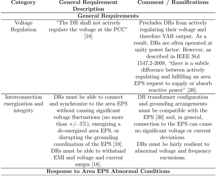
A summary of the standard’s key requirements and specifications, especially those that are the most relevant to the work of this thesis, are summarized in Table 2.2; this summary is by no means exhaustive and the categorization used is not meant to match that used in IEEE 1547-2003.
Table 2.2: Summary of Key Interconnection Requirements and Specifications in IEEE Std 1547-2003
Category General Requirement Description
Comment / Ramifications General Requirements
Voltage Regulation
“The DR shall not actively regulate the voltage at the PCC”
[18]
Precludes DRs from actively regulating their voltage and therefore VAR output. As a result, DRs are often operated at
unity power factor. However, as described in IEEE Std 1547.2-2008, “there is a subtle
difference between actively regulating and fulfilling an area EPS request to supply or absorb
reactive power” [30]. Interconnection
energization and integrity
DRs must be able to connect and synchronize to the area EPS
without causing significant voltage fluctuations (no more
than +/- 5%), energizing a de-energized area EPS, or
disrupting the grounding coordination of the EPS [18]. DRs must be able to withstand
EMI and voltage and current surges [18].
DR transformer configuration and grounding arrangements must be compatible with the
EPS [30] and, in general, connection to the EPS can cause
no significant voltage or current deviations.
DRs must be fairly resilient to abnormal voltage and frequency
excursions. Response to Area EPS Abnormal Conditions
Fault detection and reconnection
DRs must “cease to energize the Area EPS for faults on the Area EPS [. . . ] prior to reclosure by
the Area EPS” [18]. After disconnecting for any reason (fault detection, out of specified voltage or frequency range, etc.) the DR must wait a
fixed delay and then cannot reconnect until area EPS conditions (voltage, frequency, etc.) are in the proper range [18].
DRs are essentially supposed to get out of the way as quick as
possible in the event of any abnormal grid condition and let the utility system try to recover.
Voltage and Frequency
response
DRs must cease to energize the EPS within a specified time and
may not reconnect to the area EPS if the rms voltage or frequency deviates from a specified range. This range can
be fixed or adjustable for units <= 30 kW peak and must be adjustable for units > 30 kW. A
table of default voltage and frequency ranges and associated clearing times is given in Table 1
and Table 2, respectively, of IEEE Std 1547-2003 [18]. Adjustable settings are to be coordinated with the Area EPS.
The default voltage and frequency ranges and associated
clearing times are generally viewed as being too conservative.
However, the use of alternative settings, as long as they are coordinated with the area EPS,
Power Quality The DR must not contribute to objectionable levels of DC current injection, flicker, or harmonic current distortion at
the area EPS PCC.
IEEE Std 1547 essentially adopted the “Recommended
Practices for Individual Consumers” of IEEE Std 519-1992, IEEE Recommended Practices and Requirements for Harmonic Control in Electrical Power Systems [31]; for example,
the established maximum harmonic current distortion requirements listed are directly
from Table 10.3, “Current Distortion Limits for General Distribution Systems”, of IEEE
Std 519-1992. Many of these power quality issues were particularly relevant in the days
of line commutated inverters, but modern pulse width modulation (PWM)-controlled
inverters generally meet these requirements with relative ease.
Islanding If an island is unintentionally formed the DR must detect it and get offline within 2 seconds.
Unintentional islanding can cause a number of issues including significant power quality deviations (e.g. transient
or temporary overvoltage), potential damage to other DRs, customer, and utility equipment caused by out-of-phase reclosing
when utility connection is restored or from continued operation under conditions for
which the equipment was not designed, and increased safety hazards and restoration time for
both the utility and the public due to DRs, customer loads, and
portions of the utility distribution system that may
remain energized during the islanding event; hence, the
requirement to avoid unintentional islands. The role
of the DR in an intentional island is addressed in IEEE Std
1547.4-2011.
2.2.2 Gaps
The requirements in IEEE Std 1547-2003 were “designed around low penetrations of DG, with the idea that the DG should disconnect from the utility system when there are any signs of trouble with utility operations such as faults, outages, and voltage sags and swells. This is to allow the utility to correct the problem before the DG would come back online” [26]. However, as the proliferation of DR has increased, this approach has been shown as being no longer adequate. For example, one of the conclusions after investigating the 2003 Italian blackout was that “due to its significant penetration level, the effect of the distributed generation may no longer be neglected and appropriate technical requirements need to be defined”. This is because under the current requirements DRs not only don’t contribute
to the system’s recovery, they actually hasten it through positive feedback: when a large number of devices all trip at the same time on relatively tight voltage/frequency limits, it makes the system recovery even more difficult for the remaining generation assets. Clearly, as DR forms a larger and larger portion of EPS generation, their combined contribution plays a larger and larger role when the utility system attempts to recover from a grid abnormality and cannot be ignored” [32].
DRs have a valuable role to play in supporting the grid in abnormal grid conditions, but also during normal operation; the provision of key ancillary services such as voltage control, frequency regulation, load following, spinning reserve, peak shaving, harmonic compensa-tion, and network restoration is critical to operation of the grid [33] and, as such, suppliers of ancillary services are often well compensated. Thus, in many situations, DRs are made significantly more valuable because of their ability to provide ancillary services and become economically viable when perhaps they weren’t previously on a pure energy basis. Histor-ically, most of these ancillary services are provided by traditional generators. However, as more and more DRs come online, the capability of providing these key ancillary services and grid support functions can easily shift to individual DRs. In fact, this approach is actually more effective as each DR supports its local area meaning that less of the EPS distribution and transmission system assets are used for transmitting real and reactive power required to support the grid and can instead be used for transferring power for energy supply. In order for widespread provision of ancillary services from DRs, key requirements of IEEE Std 1547, such as the preclusion of actively regulating voltage and tight voltage and frequency operating requirements, must change.
This change is being addressed by IEEE P1547.8 and IEEE P1547a. IEEE P1547.8, Draft Recommended Practice for Establishing Methods and Procedures the Provide Supplemental Support for Implementation Strategies for Expanded Use of IEEE Standard 1547 [34], which is described in further detail in following sections, specifically addresses how to use the existing IEEE 1547 standard in ways to provide these functionalities. For example, the
existing standard doesn’t prohibit non-active voltage regulation or the use of alternative voltage and frequency operating ranges as long as they are coordinated with the area EPS; IEEE P1547.8 provides recommendations on how to leverage these existing flexibilities in the standard to address some advanced ICS functionalities. The development of IEEE P1547.8 also provides a method of identifying what may need to change in the IEEE Std 1547-2003. These recommendations for change are then used in the IEEE P1547a effort, which will formally amend IEEE Std 1547-2003 to include those changes.
2.2.3 Applicability of IEEE Std 1547 and Relation to UL 1741 and Other Stan-dards
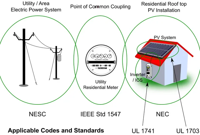
As described above, IEEE Std 1547 provides the technical requirements and specifications for interconnection of a DR to the EPS; as such, it applies at only one point in the electrical system—the PCC between the DR and the EPS. IEEE Std 1547 does not apply to the area EPS itself. For example, depending on the situation, a particular DR could be interconnected through a home or building (e.g. roof top PV connected through an inverter into the home or building’s electrical system – see Figure 2.1) or could be directly connected to the utility’s distribution system (e.g. a single 1 MW wind turbine connected into a utility substation). In these cases, it is likely the U.S. National Electrical Code [35] and the National Electrical Safety Code [36], respectively, that apply to the area EPS (at least for U.S. installations). Separate codes and standards then apply to the DR’s ICS and related equipment as well. For example, many utilities require that any installed DR ICS be certified to UL 1741 Standard for Inverters, Converters, Controllers, and Interconnection System Equipment for use with Distributed Energy Resources [37]. UL 1741, which was created before IEEE Std 1547 was even published, ensures that the ICS equipment is safe and will operate in an expected manner; for example, this includes the enclosure, mechanical assembly, wiring, bonding, spacing, shock hazard, electrical overcurrent and ground fault protection, etc. aspects of the ICS. After the publication of IEEE Std 1547-2003, UL 1741 was harmonized with IEEE Std 1547 so that any ICS that is certified to UL 1741 will meet the requirements of IEEE Std
1547. Certainly additional codes and standards may apply depending on the installation (e.g. UL 1703 [38] applies to PV modules).
KILOWATT HOURS
100 120 2 1S 15 276X140677 CL V W FM TA
CAT276X140677
NESC
IEEE Std 1547
NEC
UL 1741
Point of Common Coupling Residential Roof top PV Installation Inverter / ICS PV System Utility Residential Meter Utility / Area Electric Power System
UL 1703
Applicable Codes and Standards
Figure 2.1: Illustration of where various interconnection-related codes and standards apply
2.3 IEEE Std 1547.1
IEEE Std 1547.1-2005 “specifies the type, production, and commissioning tests that shall be performed to demonstrate that the interconnection functions and equipment of the distributed resource (DR) conform to IEEE Std 1547” [39]. To do so, it provides detailed procedures to test whether a DR conforms to each of the individual requirements set forth in IEEE Std 1547. Of these individual requirement test procedures, this thesis focuses on the series of abnormal voltage, abnormal frequency, and unintentional islanding tests as these are the most complex and most repeated tests. Each of these tests are briefly reviewed below.
2.3.1 Abnormal Voltage Tests
The purpose of these tests is to verify that the ICS ceases to energize the Area EPS when the voltage magnitude at the PCC between the ICS and the EPS deviates outside of a nominal range. A default set of the specific limits that constitute an overvoltage or undervoltage condition are specified in IEEE Std 1547-2003 [18]. For both of these conditions, the exact voltage magnitude at which the ICS ceases to energize the area EPS (“magnitude test”) and the amount of time between when the abnormal voltage is first observed and when the ICS actually ceased to energize the area EPS (“time test”) must be measured and evaluated against the specifications in section 4.2.3 of IEEE Std 1547-2003.
The process of determining the voltage magnitude at which the ICS ceased to energize the area EPS is described in section 5.2 of IEEE Std 1547.1 [39] and is shown in the generic parameter trip magnitude test function representation in Figure 2.2. The process begins by holding the voltage at the terminals of the ICS at nominal magnitude (Pn) and frequency
until the ICS begins normal operation. Next, the voltage magnitude is stepped to the starting voltage (Pn), which is within 10% of, but not exceeding, the trip point magnitude, and held
at this point for Th, at least two times the trip time setting. Finally, a slow ramp of the
voltage magnitude at slope Mramp occurs until the ICS ceases to energize the area EPS, at
which point the voltage magnitude is recorded. IEEE Std 1547.1 defines Mramp based on the
time-delay setting and stated accuracy of the ICS [39]. This procedure is then repeated for a total of five tests. If the ICS is a multiphase device or if the trip magnitude is adjustable, additional repetitions are necessary.
To identify the amount of time from when the ICS observes an abnormal voltage to when the ICS actually ceases to energize the area EPS, the procedure in section 5.2 of IEEE Std 1547.1 [39] and the generic parameter trip time test function represented in Figure 2.3 is used. As with the trip magnitude test, the trip time test begins by holding the voltage at the terminals of the ICS at nominal magnitude and frequency until the ICS begins normal operation. Next, the voltage magnitude is stepped to the starting voltage (or starting
pa-Pb Pn
Tpt Th Ttest
Trip Magnitude (Ramp) Test
Mramp
ON OFF
ICS turns ON ICS ceases to energize area EPS Time P aramet er Un de r T est (V olt ag e or F re qu en cy )
Figure 2.2: Representation of trip magnitude test function (Based on Figure A.2 of IEEE Std 1547.1 [39])
rameter, Pb), which is within 10% of, but not exceeding, the trip point magnitude, and held at this point for Th, at least two times the trip time setting. Finally, the voltage magnitude
is again stepped, this time to Pt (a point well beyond the trip setting) and held until the
ICS disconnects. The amount of time between when the step to Pt was finished and when
the ICS ceased to energize the area EPS is then recorded. This procedure is repeated for a total of five tests. If the ICS is a multiphase device or if the trip magnitude is adjustable, additional repetitions are necessary [39].
2.3.2 Abnormal Frequency Tests
The purpose of these tests is to verify that the ICS ceases to energize the Area EPS when the frequency of the voltage at the PCC between the ICS and the EPS deviates outside of a nominal range. A default set of the specific limits that constitute an overfrequency or underfrequency condition are specified in IEEE Std 1547-2003. For both of these conditions, the exact frequency at which the ICS ceased to energize the area EPS (“magnitude test”) and the amount of time between when the abnormal frequency is first observed and when the ICS actually ceased to energize the area EPS (“time test”) must be measured and evaluated
Pt Pb Pn
Tpt Th Ttest
Trip Time (Step) Test
ON OFF
ICS turns ON ICS ceases to energize area EPS Time P aramet er Un de r T est (V olt ag e or F re qu en cy )
Figure 2.3: Graphical representation of trip time test function (Based on Figure A.3 of IEEE Std 1547.1 [39])
against the specifications in section 4.2.4 of IEEE Std 1547-2003.
The procedures for conducting abnormal frequency tests, which are given in section 5.3 of IEEE Std 1547.1 [39], are essentially identical to those described for the abnormal voltage tests, except that the parameter being modified is the frequency of the voltage rather than the magnitude of the voltage. Also, the starting frequency (Pb) is to be within 1% of the trip
magnitude. Thus, for both the trip magnitude and trip time tests, the same procedures and generic parameter test functions (shown in Figure 2.2 and Figure 2.3) are followed except that the parameter under test is frequency.
2.3.3 Unintentional Islanding
The purpose of this test is to verify that the ICS ceases to energize the Area EPS when an unintentional island condition is present. Such a condition occurs when “a portion of an Area EPS is energized solely by one or more local EPSs through the associated PCCs while that portion of the Area EPS is electrically separated from the rest of the Area EPS” [39]. In other words, the portion of the EPS to which the ICS is connected becomes isolated, or islanded, from the rest of the Area EPS such that the voltage magnitude and frequency are
no longer being regulated by the Area EPS. Per IEEE Std 1547-2003, an ICS should detect such a condition and cease to energize the area EPS within two seconds [18].
To verify this, IEEE Std 1547.1 prescribes a test (section 5.7 of IEEE Std 1547.1 [39]) in which the ICS is placed in parallel with a resonant RLC load, which very closely matches the real and rective power output of the ICS, minimizing the current supplied by the simulated area EPS (through switch S3). Once this condition has been achieved, the simulated area EPS is then disconnected by opening switch S3, leaving the ICS in an island condition, which it must detect. The resonant RLC load is used in order to replicate a worst-case condition in which an ICS could be found to be energizing a local EPS that has resonant properties and thus might appear to be energized by the area EPS, when in reality it is not.
The procedure for this test begins with connecting the ICS in parallel with a resonant RLC load through a breaker or other electrical disconnection device (S3) to the simulated Area EPS as shown in Figure 2.4. The simulated Area EPS is then set to output voltage of nominal magnitude and frequency until the ICS begins normal operation. Once the ICS is online, the resonant RLC load is tuned until it absorbs all real power provided by the ICS, is operating at a quality factor (described in much more detail in IEEE Std 1547.1, quality factor is essentially a measure of how resonant a particular RLC circuit is and the ratio of real to reactive power in that resonant circuit) of 1 ± 0.5, and the fundamental frequency current through S3 is less than 2% of the rated current of the ICS on a steady-state basis. Switch S3 is then opened and the time between the opening of the switch and when the ICS ceases to energize the RLC load is recorded. This procedure is then repeated multiple times for varying reactive power settings of the load (in 1% increments), with various output power settings of the ICS [39].
2.4 IEEE Std 1547.2
As described in section 2.2, IEEE Std 1547-2003 is a very brief document that focuses solely on concise statements of requirements and specifications for interconnection of DRs and provides no background, further interpretation, or application guidance of said requirements;
Resonant RLC Load ICS Simulated Area EPS S3
Figure 2.4: Unintentional islanding test circuit (Simplified version of Figure 2 of IEEE Std 1547.1 [39])
IEEE Std 1547.2-2008 [30] fills that gap by providing very detailed information as to the interpretation, background, and impact of each requirement in IEEE Std 1547-2003 as well as application guidance, tips, techniques, and rules of thumb to aide implementation of each requirement. For example, IEEE Std 1547-2003 provides only a simple statement regarding the requirement regarding voltage regulation: “The DR shall not actively regulate the voltage at the PCC. The DR shall not cause the Area EPS service voltage at other Local EPSs to go outside the requirements of ANSI C84.1-1995, Range A” [18]. However, IEEE Std 1547.2-2008 provides much greater detail, such as that regarding interpretation: “there is a subtle difference between actively regulating and fulfilling an area EPS request to supply or absorb reactive power” [30]; background on voltage regulation, typical utilization equipment, voltage limits from ANSI C84.1 Range A [40], etc.; the potential impacts of DR on utility voltage regulation schemes; and rules of thumb as to when to expect voltage regulation issues due to DRs. Overall, IEEE Std 1547.2-2008 is an extremely valuable resource for understanding IEEE Std 1547 and interconnection issues in general.
2.5 IEEE Std 1547.3
IEEE Std 1547 provides specific interconnection requirements that describe how a specific DR or group of DRs must interact with the area EPS at a single PCC. However, the
success-ful integration of DRs with an area EPS is much more complex than just the requirements for a DR at a single PCC: oftentimes, complex EPS voltage regulation, system protection, and general operation schemes that span large portions of the distribution system are required. In order to properly integrate DRs into these complex schemes, successful monitoring, infor-mation exchange, and control (MIC) between the area EPS and the DR must occur. The successful implementation of MIC involves translation of existing EPS business and oper-ations processes and DR control and monitoring capabilities into an information exchange model; this model is then used in conjunction with effective protocols and security measures for data transfer between the area EPS and the DR to facilitate full participation of a DR in complex EPS voltage regulation, system protection, and general operation schemes. IEEE Std 1547.3-2007 [41] provides an effective guide to this process of implementing MIC for interconnection of DRs in EPSs; it includes general information about MIC and guidance on data exchange, business and operations processes, information exchange models, protocol is-sues, and information security. It should be noted that the more recent IEEE Std 2030-2011 IEEE Guide for Smart Grid Interoperability of Energy Technology and Information Technol-ogy Operation with the Electric Power System (EPS), and End-Use Applications and Loads [42] addresses the role of MIC at the area EPS and DR level in the larger requirements of an interoperable advanced EPS architecture.
2.6 IEEE Std 1547.4
As described in section 2.2, IEEE Std 1547-2003 provides specific requirements for how DRs should function in the event of an unintentional island, but intentional islanding (e.g. microgrid) scenarios are left for “consideration for future revisions of this standard” [18]. IEEE Std 1547.4-2011, IEEE Guide for Design, Operation, and Integration of Distributed Resource Island Systems with Electric Power Systems [43], provides further guidance as to the application of DR in intentional islanding scenarios. The standard provides an overview of DR island systems and guidance for planning, engineering, and operation of a DR island system.
2.7 IEEE P1547.5
The purpose of IEEE P1547.5, Draft Technical Guidelines for Interconnection of Electric Power Sources Greater Than 10 MVA to the Power Transmission Grid, was to “provide guidelines regarding the technical requirements, including design, construction, commission-ing acceptance testcommission-ing, and maintenance performance requirements, for interconnectcommission-ing dis-patchable electric power sources with a capacity of more than 10 MVA to a bulk power transmission grid” [29]. As of December 2011, it has been withdrawn and is thus unlikely to be published in the near future.
2.8 IEEE Std 1547.6
The majority of U.S. electric distribution systems are operated radially; that is, each com-ponent has a unique path to a source of energy (i.e. there are not multiple parallel paths, which could form a loop or mesh, between the source and the load) [44]. However, multiple path distribution systems, known as secondary networks, are employed to “provide highly reliable electric service to concentrated load centers” [45] and critical infrastructure such as hospitals or airports. EPS distribution secondary networks require special voltage regula-tion, system protecregula-tion, and operation schemes as compared to radial systems. For example, because secondary networks generally involve a network of loads connected through parallel paths served by multiple feeds from a utility substation, there is a potential to have circulat-ing currents, which complicate system protection and take up distribution system capacity; as a result, devices called network protectors are often employed to prevent reverse flow through substation feeds, minimizing large circulating currents. The prevention of reverse flow through a network protector is one example of an additional consideration for inter-connecting DR with secondary networks. IEEE Std 1547.6-2011 [45] provides an overview of secondary network systems, considerations for interconnecting DRs with networks, and potential solutions for such interconnections.
2.9 IEEE P1547.7
As the proliferation of DR has increased, more and more high penetration DR scenarios, which often require further study and new integration techniques, are occurring. IEEE P1547.7 [46] helps power system owners, operators, and regulatory bodies understand when additional studies and integration techniques might be necessary and provides a guide for performing such DR interconnection impact studies.
2.10 IEEE P1547.8
As described in section 2.2.2, the requirements in IEEE Std 1547-2003 were “designed around low penetrations of DG, with the idea that the DG should disconnect from the utility system when there are any signs of trouble with utility operations such as faults, outages, and voltage sags and swells. This is to allow the utility to correct the problem before the DG would come back online” [26]. As greater proliferation of DRs has occurred, the need for DRs to play a more active role in grid support functions, such as the provision of ancillary services or assistance during fault recovery scenarios, has become apparent. Thus, the purpose for IEEE P1547.8 is to “address industry driven recommendations and NIST Smart Grid standards framework recommendations (e.g., NIST priority action plans). The P1547.8 example considerations include: low voltage ride thru; volt-ampere reactive support; grid support; two-way communications and control; advanced/interactive grid-DR operations; high- penetration/multiple interconnections; and interactive inverters” [29].
CHAPTER 3
HARDWARE-IN-THE-LOOP SIMULATION TECHNIQUES
This chapter will introduce HIL simulation techniques, describe typical methods of lever-aging them in EPS-related applications, and present a literature review of how such tech-niques have been used in previous work.
3.1 Basics and Terminology
HIL simulation techniques allow for hardware systems and software models to be placed together into a single closed-loop simulation. This is accomplished through the use of a Real-time Simulator (RTS) (see Figure 3.1), which executes the software model and the communication interface between the software model and the hardware system determinis-tically and in actual time (i.e. one second in simulation time occurs in one second of actual time–crucial when interfacing simulations and hardware systems).
Measurement Conversion Control Signal Conversion
Software
Model
Real-Time Simulator (RTS) SensorHardware
System
A ct uatorFigure 3.1: Typical HIL Simulation Architecture
In doing so, outputs from the hardware system (e.g. output current in the case of an ICS) can be measured and converted to digital values for use as inputs to the software model. The outputs of the software model are then calculated and these digital outputs converted to
analog outputs (e.g. inverter gate drive signals, breaker control, grid simulator control signal, etc. depending on the application) that are sent to the hardware system. This entire process of converting hardware measurements, using those measurements to calculate the outputs of a software model, and outputting control signals is accomplished in a single simulation time step. To function correctly, the software model must accurately reflect the dynamics of the physical system it is simulating and the adjustable simulation time step must be long enough that the computation required for the entire process can be completed in that time, but short enough that the software model can respond faster than any output dynamics of the hardware system.
The value of HIL simulation techniques is that they provide a platform for rapid de-velopment of any portion of a closed-loop control system, whether it is based in hardware, software, or both. For example, in an earlier work [47] by this author, Controller Hardware-in-the-Loop (CHIL) methods (described in further detail in section 3.2.3) were used to rapidly develop a controller for a PV inverter. In that case, a hardware controller board was inter-faced to a RTS so that it could be connected, in a closed loop, to a software model of the PV inverter hardware with its PV system and local EPS connections. This test configuration allowed for development of control algorithms without needing to have a physical inverter, PV system, or connection to the local EPS. Beyond the obvious advantage of being able to develop a hardware-implemented controller without having to rely on physical inverter hardware, this approach also offers the very powerful capability to develop control algorithms that are robust across a wide variety of simulated PV system and local EPS conditions that might be difficult or unsafe to imitate with real hardware. Many other variations of this same example are also useful. For instance, the opposite case–having a PV inverter controller im-plemented in software on the RTS and using that to control physical PV inverter hardware that might be under development–further demonstrates the value of HIL techniques. Further examples and details as to the various methods of employing HIL techniques will be given in section 3.2.
While a variety of development scenarios that leverage HIL are possible, the technique is most often employed to connect a hardware system, for which no good or known model exists, to a software model of a well-known system for which good models do exist. In the context of EPSs, this could be a newly-developed ICS with advanced functionalities, connected to a simulated local EPS through a power amplifier interface such as a grid simulator. In this case, the hardware ICS is utilized as it is not yet very well known, being newly developed, while the local EPS is simulated because many good models of distribution systems exist. This arrangement then allows for the evaluation of the newly-developed ICS in the same conditions that it would see if connected to the actual EPS, but without having to take the risk of “live”, at-power testing of an unknown system.
Regardless of the development scenario or HIL implementation, a RTS is required. In many applications, including all of the work described in this thesis, a commercially-produced RTS is employed primarily due to their ease of use. In the end, each RTS ends up implement-ing a software model usimplement-ing low-level computer instructions that configure and run a real-time processor, Digital Signal Processor (DSP), or Field-Programmable Gate Array (FPGA). Commercially-produced RTSs typically provide a method to develop models in a high-level, visual programming language, such as the Mathworks’ Simulink [48], RTDS Technologies’ RSCAD [49], or National Instruments’ LabVIEW [50], which can then be compiled into low-level computer instructions, executed, monitored, etc. using a software tool specific to that RTS. Commercial simulators also typically offer pre-developed analog and digital I/O interfaces that easily integrate into visually-programmed models. However, because of the cost of commercial RTSs, custom-developed solutions–which often lack many of the same ease-of-use features, but can be significantly cheaper–are commonly used in simple (e.g. RTS as Controller with a simple device) or highly customized applications. An example of a custom-developed RTS platform is the real-time virtual test bed developed in [51] for use in testing power electronics.
3.2 Types of HIL Testing
As described above, HIL simulation techniques can be leveraged in a wide variety of different configurations towards development of various parts of a closed-loop system; thus, the term HIL is used frequently for a wide variety of different implementations, often making it difficult to understand exactly how, or even if, HIL techniques, per the definition given previously in section 3.1, are being used in a particular study. To that end, this section will help clarify this issue by describing the four most frequently-used methods of employing HIL techniques using common terminology.
3.2.1 RTS-based Simulation Only
Employing a RTS to simulate a modeled system in real-time is a first step towards using HIL techniques. This application is not strictly an implementation of HIL (per the definition given in section 3.1) because no part of the simulated system is implemented in hardware; however, it is distinct from most computer simulations in that the model is executed in real time. This approach is often needed for successful HIL simulation as traditional software models typically require further refinement of their numerical methods and parallel computing capability in order to become viable real-time models. RTS-based simulation is often employed in real-time comparisons of a hardware system with its modeled version or to develop initial discrete real-time models that can later be implemented as part of a HIL simulation. For example, this simulation method is employed in [52] to develop a real-time model of a PV module capable for later use in controlling a power amplifier to behave like a PV panel. Specifically, the authors developed a dynamic PV panel model, which they then optimized for real-time simulation and verified against empirical data from the actual PV module being modeled. RTS simulation methods are also often useful for simulating a system in actual time that might otherwise take much longer. This is demonstrated in [53] where the authors developed a real-time model that approximates the electrical system on the Hawaiian island of Lanai, which they used, in conjunction with a model of a large
![Figure 2.4: Unintentional islanding test circuit (Simplified version of Figure 2 of IEEE Std 1547.1 [39])](https://thumb-eu.123doks.com/thumbv2/5dokorg/4335085.98384/40.918.247.675.128.355/figure-unintentional-islanding-circuit-simplified-version-figure-ieee.webp)