Compacted Graphite Iron:
On Solidification Phenomena Related
to Shrinkage Defects
Doctoral Thesis
Doctoral Thesis in Materials and Manufacturing Compacted Graphite Iron:
On Solidification Phenomena Related to Shrinkage Defects Dissertation Series No. 046
© 2019 Björn Domeij Published by
School of Engineering, Jönköping University P.O. Box 1026 SE-551 11 Jönköping Tel. +46 36 10 10 00 www.ju.se Printed by BrandFactory AB 2019 ISBN 978-91-87289-49-1
ABSTRACT
An improved understanding of solidification of compacted graphite iron (CGI) is necessary to predict shrinkage related casting defects. Spheroidal graphite is not only found in ductile iron (SGI) but usually also in CGI, but its characteristics and role in this material is less understood. Uncertainties also remain regarding the segregation of alloying elements in cast irons. This is important because of its important role in the solidification process. The dendritic austenite structure has received little attention in cast iron research. A good understanding of the development of this structure is important to understand feeding of melt through the solidifying material. Nodularity is a measure of the amount of spheroidal versus compacted graphite in the microstructure. At a lower nodularity, the compacted graphite tips were found to grow in contact with the melt for a longer time before being encapsulated in the austenite. Moreover, as the nodularity was reduced, the subpopulation of larger spheroidal graphite gradually disappeared, reducing the bimodal size distribution to unimodal.
Segregation of Si, Mn and Cu in SGI and CGI with a solidification time of near 10 min was found to be rather predictable under assumptions of no diffusion in austenite and complete mixing in the melt. Gradients of these elements contribute to a decrease in the driving force for diffusion of carbon into the austenite from the liquid, which is important for the growth of graphite which is separated from the liquid by austenite. During solidification of a near-eutectic CGI, the carbon concentration of austenite was found to deviate considerably from local equilibrium with graphite during solidification. This is important to consider in growth models for graphite by diffusion of carbon through a barrier of austenite.
Micropores were shown to have displaced liquid from the solid structure at a late stage of solidification when solidification was slowing down and the temperature of the casting was falling at an increasing rate.
The development of dendritic austenite in a near eutectic CGI was investigated. The contact area between liquid and the dendritic structure exceeded the contact area between liquid and eutectic cells through the dominant part of solidification. This highlights the importance of good understanding of the development of this structure in order to predict feeding of melt through the solidifying material. The coarsening of the structure was found to proceed at a higher rate compared to studies under isothermal condition. The dendritic structure continued to grow in parallel with the eutectic by a combination of thickening and dendritic growth.
Keywords: Compacted graphite iron, Spheroidal graphite iron, Solidification, Microsegregation, Porosity
SAMMANFATTNING
En förbättrad förståelse av stelningsförloppet hos kompaktgrafitjärn (CGI) är nödvändig för att förutbestämma krymprelaterade gjutdefekter. Nodulär grafit förekommer inte bara i segjärn (SGI) utan vanligtvis även i CGI, men dess karaktär och roll är mindre känd för detta material. Osäkerheter kvarstår även kring segring av legeringsämnen i gjutjärn, vilket spelar en viktig roll under dess stelningsförlopp. Dendritisk austenitstruktur har fått relativt lite uppmärksamhet bland forskare inom gjutjärn. God kunskap om dess utveckling är viktigt för att förstå matning av smälta genom stelningsförloppet.
Nodularitet är ett mått på andelen nodulär kontra kompakt grafitmorfologi i mikrostrukturen. Vid lägre nodularitet visades kompaktgrafitens extremiter växa i kontakt med smältan en längre period innan de inneslöts av austenit. Gruppen av större nodular försvann dessutom gradvis vid lägre nodularitet, vilket reducerade den starkt bimodala storleksfördelningen till unimodal.
Segring av Si, Mn och Cu i SGI och CGI med stelningstid på nära 10 min fanns förutbestämbar under antaganden om obetydlig diffusion i austenit och omedelbar blandning med smältan. Gradienter av dessa element bidrar till en sänkt drivkraft för diffusion av kol mot austenitens inre, vilket är viktigt för tillväxt av nodulär grafit. Under stelning av ett nära eutektiskt CGI fanns kolhalten i austenit avvika avsevärt från lokal jämvikt med grafit under stelningen. Detta är viktigt att ta hänsyn till i modeller för tillväxt av grafit genom diffusion av kol genom en barriär av austenit. En studie av mikroporer visade att dessa trängt undan smälta mellan stelnad struktur i ett sent stadie av stelningen, med avtagande stelningshastighet och ökande temperaturfall.
Utvecklingen av dendritstruktur i ett nära eutektiskt kompaktgrafitjärn undersöktes. Smältans kontaktyta mot denna struktur överskred kontaktyta mot eutektiska stelningskroppar genom större delen av stelningen. Detta visar att en god förståelse för dendritstrukturens utveckling genom stelningen är viktig för att beskriva matning av smälta genom stelnande struktur. Förgrovning av strukturen visades fortskrida i högre takt genom stelningen jämfört med studier vid isotermiskt tillstånd. Dendritstrukturen fortsatte växa parallellt med eutektisk stelning genom en kombination av homoepitaxial och dendritisk tillväxt.
ACKNOWLEDGEMENTS
I express my sincere gratitude to:
My supervisor Attila Diószegi for his encouragement, inspiring discussions, guidance and support throughout this work.
Juan Carlos Hernando and Baiwei Zhu for their friendship, help and interesting discussions.
Kaj Grönlund and Gunilla Runnsjö for their contagious enthusiasm and inspiring work with the microprobe.
Jessica Elfsberg for her shared curiosity and her much appreciated support and feedback.
Taishi Matsushiita for his valuable feedback.
Lucian Vasile Diaconu for his support and help during the work.
Laboratory staff for their help during workshop activities and making sure the equipment works: Jörgen Bloom, Peter Gunnarson and Lars Johansson. Special thanks to Esbjörn Ollas for his work on the experimental equipment.
To all colleagues at the department of materials and manufacturing who make up a friendly and inspiring environment.
To my parents, Bryngel and Karin Domeij for their love and support during this work.
All participants of the Spofic II project and the involved industrial partners Scania CV AB, Volvo Group AB, Swerea SWECAST, for their valuable contributions to the work, and to Vinnova for the financial support of the research project.
Björn Domeij Jönköping 2019
SUPPLEMENTS
The following supplements constitute the basis of this thesis:
Supplement I B. Domeij, J.C. Hernando, A. Diószegi, Size distribution of Graphite Nodules in Hypereutectic Cast irons of varying Nodularity, Metallurgical and Materials Transactions B, 2018, 45(5), p. 2487-2504
Björn Domeij is the main author. Juan Carlos provided suggestions regarding the experimental work. Attila Diószegi supervised the work.
Supplement II B. Domeij, A. Diószegi, Inferring the development of microsegregation and microstructure in Spheroidal and Compacted Graphite Iron using EPMA‐WDS, Proceedings of the 6th Decennial International Conference on Solidification
Processing, Ed. Zhongyun Fan, BCAST, 2017, p. 455-458 Björn Domeij is the main author, Kaj Grönlund and Gunilla Runnsjö performed the EPMA, Attila Diószegi supervised the work.
Supplement III B. Domeij, A. Diószegi, Solidification Chronology of the Metal Matrix and a Study of Conditions for Micropore Formation in Cast Irons using EPMA and FTA.
Metallography, Microstructure, and Analysis, 2016, 5(1): p. 28-42.
(SPCI Young researcher award)
Björn Domeij is the main author. Kaj Grönlund and Gunilla Runnsjö performed the EPMA, Attila Diószegi supervised the work.
Supplement IV B. Domeij, J.C. Hernando, and A. Diószegi, Quantification of Dendritic Austenite After Interrupted Solidification in a Hypoeutectic Lamellar Graphite Iron. Metallography, Microstructure, and Analysis, 2016, 5(1): p. 28-42. (Selected as an Editor’s choice article for 2016) (2016 Annual IMS Buehler Technical Paper Award) Björn Domeij is the main author, Juan Carlos Hernando guided the experimental work and Attila Diószegi supervised the work.
Supplement V B. Domeij, J. Elfsberg, A. Diószegi, The evolution of dendritic austenite in a solidifying near‐eutectic compacted graphite iron under varying cooling conditions, Manuscript
submitted 2018-12-18 to Metallurgical and Materials Transactions A.
Björn Domeij is the main author, Jessica Elfsberg and Attila Diószegi supervised the work.
Supplement VI B. Domeij, J. Elfsberg, A. Diószegi, The distribution of carbon during solidification of a compacted graphite iron, Manuscript
Björn Domeij is the main author, Kaj Grönlund and Gunilla Runnsjö performed the EPMA. Jessica Elfsberg and Attila Diószegi supervised the work.
TABLE OF CONTENTS
CHAPTER 1 INTRODUCTION ... 1
BACKGROUND ... 1
THE SHRINKAGE DEFECT PROBLEM ... 3
SOLIDIFICATION OF CAST IRONS ... 5
KNOWLEDGE GAPS ... 20
CHAPTER 2RESEARCH APPROACH ... 23
PURPOSE AND AIM ... 23
RESEARCH DESIGN ... 23
MATERIALS AND EXPERIMENTS ... 26
CHARACTERISATION AND TESTING ... 30
CHAPTER 3 SUMMARY OF RESULTS AND DISCUSSION ... 33
THE TRANSITION FROM SPHEROIDAL TO COMPACTED GRAPHITE IRON ... 33
MICROSEGREGATION IN SGI AND CGI (SUPPLEMENT II) ... 41
PORE FORMATION (SUPPLEMENT III) ... 43
DENDRITIC AUSTENITE IN NEAR-EUTECTIC CAST IRON (SUPPLEMENT IV AND V) ... 45
THE DISTRIBUTION OF CARBON DURING SOLIDIFICATION OF CGI (SUPPLEMENT VI) ... 50
CHAPTER 4 CONCLUSIONS ... 53
CHAPTER 5FUTURE WORK ... 59
REFERENCES……... 61
CHAPTER 1
INTRODUCTION
CHAPTER INTRODUCTION
This chapter describes the background of the work and introduces the reader to the subject area. The chapter ends with a discussion on knowledge gaps.
BACKGROUND
Increasingly stringent environmental legislation and increasing demand for improved performance and fuel economy drives an effort among truck manufacturers to design more fuel-efficient engines. The efficiency of an engine is related to the peak pressure during operation, which is limited by the capacity of the engine to resist the resulting static and cyclic thermomechanical load.
Compacted graphite iron (CGI) has been highlighted as a suitable material for the main structural components in truck engines, the cylinder head and cylinder block. In 2009, over 100,000 tonnes of CGI cylinder blocks were produced annually [1]. The material has a balanced combination of e.g. thermal and mechanical properties, castability, machinability, and vibration damping properties. Other applications which involve both mechanical and thermal loads are also common, such as brake disks, ingot moulds, and exhaust manifolds [2].
The introduction of CGI as material for these components has come with a number of challenges, mainly related to the shortage of understanding about how to control the production and properties of the material.
One challenge the manufacturers have struggled with is porosity defects. The defects are often difficult to detect, in part due to the complex shape of the component and in part due to being hidden beneath the casting surface. This leads to considerable waste and costs as defects are often detected at a late stage of production.
The formation of porosity defects in cast irons is usually attributed to a combination of gas evolution and local material deficit related to shrinkage during its solidification.
In a recent research project, porosity defects were found to be promoted by excess amounts of N and H but persisted even at levels below those normally considered critical. This has lead to the suspicion that the triggering factor is local material deficit and that more work is required to understand how such material deficit may develop. Most metals are denser in their solid state than in their liquid state [3]. This means that the metal contracts as it crystallizes, a phenomenon commonly referred to as “solidification shrinkage” [3]. The solidification shrinkage of pure iron is about
3.16%. A favorable characteristic of graphitic cast irons is that excess carbon precipitates as graphite, which has lower density than the liquid and so counteracts the solidification shrinkage of iron. The graphite precipitates mainly in parallel with the crystallization of the iron, in a eutectic reaction. The net density change of the eutectic is an expansion. For hypoeutectic compositions, a stage of crystallization of only iron precedes the eutectic reaction, leading to an initial stage of only shrinkage. For carbon equivalents over about 3.6, the expansion during the eutectic stage exceeds the shrinkage during the primary stage [3, 4].
The progress of solidification is not uniform across a casting as cooling occurs by extracting heat from its surface. A general guidelines is that solidification should ideally begin in the parts of the casting furthest away from feeding sources, such as risers and inlets [3]. The solidification front should then proceed towards the feeding sources, while staying connected through a clear path of liquid [3]. Any local density changes are in this way compensated for by movement of liquid to or from the feeding sources. However, in complex components like cylinder heads and motor blocks, with various section thicknesses and surface curvatures, this is very difficult, particularly because there is little room to compromise functionality for the sake of producibility. This poses a considerable challenge to producers.
The shrinkage defect problem
Reports on the tendency of CGI for shrinkage defect issues are mixed, indicating characteristics somewhere between LGI and SGI [5]. It has been suggested that the variation in shrinkage behavior corresponds to variation in nodularity, indicating that it is useful to think of CGI approximately as a composite of LGI and SGI depending on nodularity. For this reason, the shrinkage behavior of SGI relative to LGI is reviewed first, before CGI is treated.
Shrinkage in SGI
It is rather well established that SGI exerts a greater pressure on the mold wall during solidification [5, 6]. If the mold material and geometry are such that the elevated pressure causes the mold cavity to dilate, more feeding is required for SGI. If, in this situation, feeding is not possible, a shrinkage defect may develop. Several authors report that the feeding requirement of SGI is no different from LGI given that the mold material and design is strong enough to avoid dilatation of the mold cavity [7]. The assumption appears to be that the solid structure yields under its own load such that the expansion contributes to material feeding rather than to mold dilatation. It has been suggested that the elevated pressure on the mold wall relates to the solidification behavior of SGI. Factors such as a more “mushy” solidification morphology and weak “skin formation” relative to LGI have been mentioned [5, 6]. More specifically SGI is described as featuring a more prominent dendritic austenite structure relative to LGI.
Investigations employing dilatometry suggest that the material undergoes a period of contraction followed by a period of expansion, regardless of graphite morphology and whether the composition is hypo- or hypereutectic [7]. However, the magnitude of the two stages is larger for SGI than for LGI and the duration of the prior stage is longer. Moreover, for SGI, increasing magnesium content has been found to aggravate this effect [7]. It has been shown that shrinkage porosity issues in the casting may be avoided by adjusting the feeder neck dimensions such that connection remains open during the contraction stage [7].
It has therefore been suggested that, even if the final feeding requirement is independent of graphite shape for rigid molds, it is more important for SGI than for LGI that the connections to risers/feeders remain open during the shrinkage stage of early solidification [7].
As feeders/risers are costly, there have been efforts to achieve riserless castings through optimizing melt composition and treatment. A study involving a riserless steel die indicates that shrinkage defects may be avoided by keeping the effective graphite area fraction (discounting large spheroids assumed to be primary graphite) above 10.4 % [8]. This limit was found to hold true both when the carbon equivalent was too low and when considerable carbon had been consumed by precipitation of primary graphite). Moreover, the limit is in line with and perhaps improves on an older rule of thumb suggesting that shrinkage defects are avoided given that wt% C + 1/7 wt% Si > 3.9 [9]. However, their estimation of the effective graphite area fraction appears to be flawed as parallel growth of large and small spheroids is overlooked [8].
Shrinkage in CGI
Shrinkage tendency of CGI is less well understood. It has been reported that the feeding requirement may be slightly larger for CGI than for LGI, but considerably smaller than for SGI. Similar to SGI, this has been attributed to an elevated pressure exerted on the mold wall during solidification, causing mold dilatation [10]. The similar mold dilatation tendency of CGI to LGI has been attributed to graphite being in direct contact with the melt during eutectic growth, which is not the case for SGI [11].
The solidification morphology of CGI and SGI has been investigated by measuring the evolution of solid fraction through solidification [11]. The solid fractions evolved similar in SGI and CGI up until about 40% solidification time, after which a layer of higher solid fraction formed near the mold in the CGI.
Feeding
Clearly, feeding is one of the more important factors contributing to material deficit. Feeding can be divided into at least five types: liquid, mass feeding, interdendritic feeding, burst feeding and solid feeding [3].
Liquid feeding is simply flow of the liquid, restricted mainly by its viscosity and the geometry of the space through which it flows [3].
Mass feeding is defined as the movement of solid structure together with the liquid, collectively referred to as a “slurry”. The feeding behavior differs from that of liquid in that its viscosity depends on the shear rate [12]. However, according to a casting handbook, mass feeding is usually too early in the feeding process to be responsible for feeding issues [13].
Metals typically crystallize dendritically, forming a tree-like structure with branches. Once a rigid structure of this type has formed, liquid must pass between the branches, which is termed interdendritic feeding. This problem may be treated as fluid flow through a porous medium, where flow is governed by the viscosity of the liquid, the permeability of the solid medium and the local pressure gradient [14-16]. The permeability in turn is related to the geometry of the dendritic structure [15, 17, 18]. Burst feeding may occur when the dendritic structure yields to the pressure gradient, allowing a burst of mass or liquid feeding [3].
Given that enough hydrostatic tension builds up in the interior of the casting, the solid exterior may deform through plastic or creep flow [3]. This is called solid feeding.
Solidification of cast irons
As shrinkage defect formation relates strongly to the density changes occurring during solidification and the permeability of the solidification structure. A good understanding of the solidification behavior of cast irons is crucial. Current understanding is reviewed here.
The Fe-C equilibrium and metastable phase diagram
Cast iron is a category of Fe-C based alloys which are differentiated from steels in that its solidification includes a eutectic reaction consisting of the iron rich phase austenite (𝛾) and a carbon rich phase which can be either graphite (G) or cementite (Fe3C). Its main solidification characteristics can be overviewed using the Fe-C
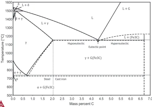
equilibrium and metastable phase diagram shown in Figure 1, which shows regions of temperature and carbon concentration where the various phases are stable at 1 atm of pressure.
Figure 1. Stable and metastable Fe‐C equilibrium phase diagram. The metastable phase diagram is superposed and represented by a dashed line.
The diagram reveals that for carbon (C) concentrations below 2.08 wt% (2.11 wt% for Fe3C), all of the C may dissolve in γ at solidus. This means that solidification may
complete without the precipitation of C-rich phases, which is the definition of a steel. Beyond this concentration, γ becomes saturated with carbon over solidus, and the
Fe-C Equilibrium Phase Diagram
0.0 0.5 1.0 1.5 2.0 2.5 3.0 3.5 4.0 4.5 5.0 5.5 6.0 6.5 7.0 Mass percent C 500 600 700 800 900 1000 1100 1200 1300 1400 1500 1600 Te m p er a tur e [°C ] γ γ G Fe3C L G L Fe3C α γ α G Fe3C L L γ L δ δ δ γ α Eutectic point
Steel Cast iron
excess C precipitates in parallel with iron as a C-rich phase in a eutectic reaction. This is the key characteristic of cast irons. As the C concentration increases beyond 2.08 wt% (2.11 wt%), the liquid-γ equilibrium line drops until it crosses with the liquid-G or the liquid-Fe3C equilibrium line. At this crossing, γ and the C-rich phase become
stable at the same temperature and is called the eutectic point. Up to this point, Cast irons are said to be hypoeutectic. Cast irons beyond this composition are said to be hypereutectic and are characterized by the carbon rich phase being stable at a higher temperature than γ.
G is the stable carbon rich phase. However, because it contains almost exclusively C, which is in rather dilute solution, its crystallization demands substantial migration of C, which takes time. Under sufficiently rapid cooling, the liquid may undercool below the metastable liquid-Fe3C equilibrium line, leading to crystallization of Fe3C in place
of G. This transformation is more rapid, as the 6.67 wt% C in Fe3C demands less
rearrangement of carbon. Fe3C is regarded metastable, because given enough time at
sufficient temperatures, it is destined to decompose into 𝛾 and G. Fe3C is hard and
brittle and does not provide expansion to compensate against solidification shrinkage as does graphite. Unless its hardness is desired and its brittleness is tolerated, the stable graphite phase is for this reason preferred.
Cast irons usually contain additional alloying elements than C to control solidification and the properties of the metal matrix. However, their main influence on the solidification characteristics are commonly represented by the binary Fe-C diagram by substitution of the carbon content with a carbon equivalent value e.g. CEV = C + 0.33 (Si + P) where C, Si and P represent the concentration of the respective elements in units of weight percent [19]. This means that an Fe-C-Si-P alloy with a CEV = 4.3 can be expected to solidify approximately as an Fe-C alloy with a carbon content of 4.3 wt%. The influence of elements vary with carbon content, so CEV is valid for a carbon content in the neighborhood of 4 wt% carbon [20]. CEV is an empirical equation, but a similar equation has been developed based on thermodynamic data [21]. This has lead researchers to suggest that additional elements should be included in the equation, such as Al, Cr and Cu [20].
Graphitizers and carbide stabilizers
Besides the influence of elements on the 𝛾-G eutectic carbon concentration, elements also influence the stability of graphite relative to Fe3C. This is of key importance in
cast irons as Fe3C is hard, brittle, a poor thermal conductor and does not compensate
against solidification shrinkage as does G. Elements which stabilize G relative to Fe3C,
such as Si, Cu, Co, Al and Ni, are categorized as graphitizers [22, 23]. Conversely, elements which stabilize Fe3C relative to G, such as Mn, Cr, Mo and W are categorized
as carbide stabilizers [22, 23]. Graphitic cast irons are for this reason alloyed with a generous amount of graphitizers, while carbidic cast irons are alloyed predominantly with carbide stabilizers. Sulphur is also a carbide stabilizer [23], but is seldom used in this regard as it plays a more prominent rule in nucleation and modification of graphite.
After solidification, the solubility of C in 𝛾 decreases with temperature. Eventually, the eutectoid concentration of C is reached, rendering austenite unstable. The eutectoid reaction involves the transformation of 𝛾 into the body-centered-cubic phase ferrite (α), and a carbon rich phase. The eutectoid point is found at the bottom
of the 𝛾 field in Figure 1. Also here, the metastable Fe3C phase may form in place of
the stable G, usually in the form of a fine lamellar structure of Fe3C and α called
pearlite. In general, the influence of graphitizers and carbide stabilizers on the stability of graphite versus Fe3C applies also to the solid-state transformation of
austenite. However, certain elements, such as Cu and Ni have the more complex but convenient property of promoting graphite in the solidification temperature range while acting as carbide stabilizers in the austenite transformation temperature range [24]. Graphitic irons typically include a balance of graphitizers and carbide stabilizers to promote graphite during solidification while at the same time promoting the eutectoid transformation of 𝛾 into pearlite.
Graphite Morphology
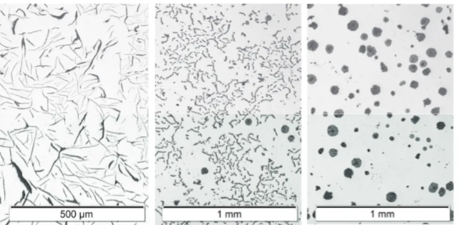
Graphite grows in many different morphologies, some of which arise from some combination of its crystallization behavior in the liquid its interaction and coprecipitation with austenite. The morphology of the graphite has a great impact on the mechanical and physical properties of the material. Commercial graphitic cast irons can be divided into three main types based on graphite morphology: lamellar graphite iron, often referred to as gray iron, compacted graphite iron, and spheroidal graphite iron, often referred to as ductile iron. Examples of the three can be viewed in Figure 2.
Figure 2. Graphite morphologies as viewed on a polished cross section of the cast iron. From left to right: Lamellar graphite, Compacted graphite, Spheroidal graphite. Note that a few spheroidal graphite is found among the compacted graphite, as is typical for compacted graphite iron. Patricia Alonso Muela is greatly acknowledged for sharing the micrograph of lamellar graphite iron.
NUCLEATION
Nucleation occurs at a time and size scale where direct observation is difficult. Theoretical descriptions have proven to development of inoculation practice. According to classical nucleation theory, it is not sufficient that a phase is thermodynamically stable, because it cannot exist without an interface against its surrounding, which is energetically expensive [25]. The energy gain from the phase transformation scales with the volume of the crystal, while the cost of the interface scales with its surface. Consequently, for a positive undercooling, there is a critical size beyond which the crystal is favoured to grow [25]. This critical size drops with increasing undercooling [25]. Nucleation occurs when the critical size falls below the size of crystal embryos generated from thermal and concentration fluctuations [25, 26].
In a conventional casting process, the liquid typically solidifies in contact with a solid mold or die and includes a variety of inclusions and dross particles. The cost of establishing an interface against these can be small compared to an interface against the liquid [25]. This allows nucleation to occur at a much lower undercooling. In general, phases which have similar crystallographic lattice structure and similar distances between atoms compared to the nucleated phase tend to serve as better nucleation agents [27]. However, atomistic simulations have revealed flaws in the classical model [28, 29]. For example, the interface thickness may be in the same order of magnitude as the initial size of the crystal nucleus, so the approximation of a sharp interface is not realistic [29]. Moreover, the energy barrier to nucleation is not a monotonous function of lattice mismatch, because large lattice mismatch may promote an amorphous layer which in turn facilitates nucleation [28].
For cast irons, a population of potential nucleation sites remains after melting of the charge material [30]. Moreover, the melt is commonly treated with inoculation and graphite modification which generates additional nucleation sites [30]. Most commercial inoculants are based on FeSi but also contain additions of e.g. Zr, Ba, Sr, Ca, Al, Ti, Mn and rare earth elements (RE) [31]. A study employing a droplet emulsion technique to study nucleation in cast irons showed that large undercooling was required to nucleate G in the presence of γ, however, low undercooling was required to nucleate γ in the presence of G [32]. This asymmetry was proposed to relate to the high G-L interfacial energy compared to γ-L. It implies that nucleation of graphite is the bottleneck to the eutectic reaction, which appears to have guided subsequent research.
1.3.4.1 NUCLEATION OF AUSTENITE
The literature concerning the nucleation of 𝛾 is relatively scarce. In hypoeutectic LGI, slow cooling, small superheating and short holding time has been found to promote nucleation of primary 𝛾 , as characterized by smaller undercooling and a larger number of more equiaxed austenite grains [33]. The influence of cooling rate on the number of 𝛾 grains is the opposite to what is observed for eutectic cells, where high cooling rate is associated with smaller and more numerous eutectic cells. The authors attributed this effect to the steep thermal gradient which promotes nucleation near the wall and subsequent growth of columnar grains.
Several inoculants have been reported to promote the number of austenite grains in hypoeutectic LGI, including SiO2 [34, 35], Fe-powder [35, 36], graphite powder [35],
Al [37] and Bi [38]. Analysis of the lattice disregistry agrees that crystalline SiO2 and
Fe-powder are suitable inoculants, but suggests that amorphous SiO2 is not [34].
Experimental results also indicate that columnar growth of the austenite grains is generally suppressed as the number of grains increases [35].
1.3.4.2 NUCLEATION OF GRAPHITE
The nucleation of graphite has been given more attention by researchers. The practice of inoculating the cast iron melt started long before heterogeneous nucleation was understood because of observed practical benefits. Much of the research on nucleation of graphite has aimed to understand the mechanisms involved in this practice. This involves determining the precise substrates on which graphite nucleates and their relative potency. Analysis of compatibility between various substrates and the graphite crystal lattice has also informed the development of new inoculant types. Today, most commercial inoculants are based on FeSi containing minor additions of e.g. Al, Ba, Bi, Ca, Ce, Mn, Sr, Ti and Zr [39].
Experience has shown that FeSi and SiC are effective as inoculants [40]. It has been hypothesized that homogeneous nucleation of graphite occurs in the supersaturated concentration fields around dissolving FeSi and SiC inoculant [40-42]. While the vicinity of FeSi has been confirmed to be supersaturated with C and populated with graphite, the evidence for homogeneous nucleation is weak [42]. A comparison between additions of FeSi and SiC showed that additions of SiC is more effective for inoculation, resulting in smaller undercooling and higher eutectic cell count [43]. Small additions of alkali, alkaline earth, and rare earth metals tend to facilitate nucleation of graphite [44]. Motivated by low lattice disregistry, it has been hypothesized that that these form salt-like carbides which act as nucleation sites [44]. Carbides are, however, rarely observed, due to their low stability in cast iron melts [45]. Among sulphides, CaS, CeS, LaS and SiS show particularly low lattice disregistry indicating that these are suitable nucleation sites for graphite [46].
Nuclei are frequently observed at the center of spheroidal graphite particles. These typically contains some combination of sulphides [45-49], oxides [48, 50-52], carbides [45], nitrides [49] and silicates [50] involving additives of mainly alkali, alkaline earth and rare earth metals.
Some studies report that the graphite nuclei hold sulphide cores surrounded by oxide shells [48], while others report the reverse [53]. It has been suggested that the sequence of the layers relates to the balance of composition and additives which control the temperatures at which sulphides and oxides become stable [53]. Others have emphasized that the balance between O and S appears sufficient to explain the discrepancy between the observations [54].
An extensive study of 933 cores of graphite spheroids showed that the vast majority consisted of MgS or MgO, often with a Ti(C,N) shell. The authors argue that the MgS and MgO cores originated from the spheriodization treatment and that the inoculation process had little impact on the composition of the cores. In LGI, MnS appears to play a more important role [53, 55-58].
Clearly, the composition of the core and the associated nucleation mechanism depends on the specific conditions, so the various theories regarding inoculation do not necessarily all compete.
High pressure (145 atm) has been shown to reduce the number of graphite nodules [59]. This implies that nucleation of graphite is facilitated by low pressure, which is reasonable as it has to perform work against this pressure to make room for itself. The number of spheroidal graphite particles is typically much larger than the number of eutectic cells in LGI and CGI, e.g. by a factor of 200 to 300 [60]. It has been suggested that this relates to the relatively deep undercooling typically observed before recalescence on cooling curves for SGI, allowing more potential nucleation sites to be activated.
The number of spheroidal graphite particles observed on a cross section is often reported to increase throughout the solidification process, indicating that nucleation is continuous, presumably because undercooling increases [11, 61, 62]. Others have found that, while the number of SG on cross sections indeed increases through solidification, in their case, the number per unit volume was constant [63]. This stresses the importance of proper translation of numbers observed on a cross section to volumetric counts, as larger spheroids are more likely to be intersected by a plane. Analysis of the size distribution often display more than one mode [64, 65], indicating that nucleation of spheroidal graphite may occur in several steps or waves.
FADING OF NUCLEATION POTENTIAL
In LGI and SGI the number of eutectic cells has been observed to drop if the melt has been exposed to longer holding before pouring as well as holding after inoculation [66, 67]. The number decreases at a higher rate at higher holding temperature [66]. The fading effect has been ascribed to a decline of the number of particles on which graphite nucleates, resulting from some combination of Ostwald ripening and coalescence [68, 69]. Ostwald ripening is a diffusion limited process driven by minimization of interfacial area where large particles grow by dissolution of smaller particles [26, 70].
PRIMARY AUSTENITE
In hypoeutectic cast irons, the primary solid phase is γ, which normally grows dendritically [37, 71-78]. The original γ grain structure is often obscured by the solid-state transformation of γ into e.g. ferrite or pearlite. However, the grain structure has been studied using a special technique involving heat treatment and etching [79]. It has revealed that the γ grain structure is similar to other metallic alloys, forming columnar and equiaxed grains [79, 80]. The dendritic structure has also been revealed by rapid cooling which forces carbidic eutectic transformation of the interdendritic liquid [81], or using etching techniques which exploit the micro-segregation patterns the den dritic structure leaves behind [74, 82, 83].
General theory regarding dendritic growth is still developing. According to recent theory, dendritic structures seems to arise through some combination of interface instabilities relating to solute and thermal gradients, interfacial energy and crystal anisotropy [84-86].
The anisotropy of the face centered cubic (FCC) γ crystal promotes growth along the six orthogonal <100> directions of the lattice [87]. When a growing γ crystal suspended in the melt reaches a certain size, primary arms develop along the preferred growth directions. Behind the tip of the primary arms, secondary arms branch off with regular spacing into the four free preferred <100> directions. The average spacing between secondary arms (SDAS) is a common measure of the coarseness or scale of the dendritic structure [88]. Tertiary arms may in turn develop on these and so on [89].
The first γ grains often develop close to the surface of the casting where not all growth directions are free. These undergo spatial competition. Grains oriented such that a preferred growth direction is more aligned with the thermal gradient take the lead and obstruct the growth of less favourably oriented grains [90]. The result is a zone of long grains dominated by the favoured orientations. This zone is often referred to as the columnar zone.
Heat is transported from the melt to the exterior through the grains. If the melt ahead of the columnar zone becomes sufficiently undercooled, additional γ grains may nucleate on particles suspended in the melt, which then obstruct the growth path of the columnar zone [91]. This process is referred to as the columnar-to-equiaxed transition (CET).
In contrast to the columnar grains, the crystals suspended in the melt are free to grow in all six of the favoured growth directions. The lack of connection to the exterior means that the released latent heat related to their growth must be transported through the liquid to the columnar zone [84].
An experiment on a hypeutectic Fe-C alloy indicated that a longer holding time at higher temperatures before pouring promoted columnar grains over equiaxed grains [33]. The effect was interpreted as fading of nucleation sites. Inoculation of hypoeutectic LGI with iron powder has been shown to refine equiaxed γ grains [92]. High cooling rate has been found to promote columnar grains [33]. The suggested explanation was that a steeper thermal gradient keeps the interior less undercooled and promotes a higher growth rate of the columnar grains.
The equiaxed grains gradually impinge on one another, restricting each other’s growth paths and form a coherent structure [93]. For LGI, this has been reported to occur at volume fractions of primary austenite (𝑓 ) around 0.335 and 0.38 [93, 94]. Following the end of dendrite tip growth, cooling causes 𝑓 to increase by thickening of the arms [94]. 𝑓 has been reported to be near the equilibrium value for a wide range of cooling rates [95]. Others suggest that it is possible to increase the final 𝑓 by adding elements which either suppress the graphite nucleation or promote nucleation of γ [38].
As long as the dendritic structure is in contact with liquid, it is subject to phase coarsening which causes morphological changes [96]. The process is described as driven by the excess energy of interfaces between phases [96, 97]. The mechanism for minimizing this energy is the curvature dependence of chemical potentials. This drives diffusion between high and low curvature interfaces which melts and crystallizes, respectively, in response [96]. Over time, this process causes a decay of interfacial surface area and an increase of the overall scale of the structure [98].
The evolution of various measures of the dendritic γ in hypoeutectic cast irons has been shown to evolve approximately in proportion to the cube root of time under constant temperature [99-101]. The initial regular branched structure has been shown to evolve towards more globular morphology [100]. After extended coarsening times fragmentation of the dendritic γ has been observed to occur [100].
PRIMARY GRAPHITE
The graphite crystal comprises monolayers of graphene with a usual stacking of ABAB, forming a hexagonal crystal [102]. The monolayers consist of carbon atoms arranged in interconnected hexagonal rings [102]. The interlayer bonds, consisting of some combination of Van der Waal forces and orbital interactions (this appears to be controversial [102, 103]), are weak relative to intralayer covalent bonds [102, 103]. This gives graphite highly anisotropic properties [104] and has been proposed to influence the growth of graphite both in terms of probability of carbon attaching to the basal plane compared to the edges and by allowing the graphite crystal to bend by having the layers slip in relation to one another [105].
In hypereutectic cast iron, graphite is the primary solid phase. Since the density is lower than the iron melt, it tends to rise due to buoyancy [106]. This phenomenon, often referred to as floatation, may cause primary graphite to accumulate in certain parts of the casting or at the melt surface, causing local defects [106, 107]. Primary graphite is generally considered undesirable in cast irons, because it provides expansion at a stage of solidification when it is the least needed while degrading mechanical properties [8].
The shape of primary graphite depends strongly on melt conditions, with plate morphology in one extreme and spheroid morphology in the other. Since the dawn of spheroidal graphite iron, there was a suspicion that additives like Ca, Mg and Ce played an indirect role and that their desulphurizing property was important to the spherodization of graphite [108]. This became evident after researchers managed to produce spheroidal graphite iron without additives using high purity Fe-C melts achieved by pure charge materials or vacuum degassing [109, 110]. This was interpreted as spheroidal graphite being the natural morphology, while-as impurities somehow modified the graphite towards more plate-like morphology. Curled plates has been observed under intermediate purity levels [111].
Another early observation was that the contact angle between liquid and graphite was lower for high purity Fe-C melts and after spherodizing melt treatment than for impure untreated melts or high purity Fe-C melts alloyed with oxygen or sulfur [112, 113]. This gave rise to the hypothesis that the active modifiers are surface active impurities, like O and S, which promote more plate-like morphologies by altering the interfacial energy between liquid and graphite [112].
It was later found that the interfacial energy between an untreated cast iron melt and graphite was lower for the prism plane than for the basal plane, which resulted in lamellar graphite [114]. After Mg and Ce treatment, the basal plane had the lower interfacial energy, resulting in spheroidal graphite. The authors concluded that graphite tends to grow along the interface which has the lower interfacial energy [114]. Later experiments have shown similar results [115].
Later theories argue that growth by nucleation of new layers on the basal plane is improbable, even in high purity melts. Instead, various crystallographic faults have been proposed to allow the crystal to grow new layers by extending over itself through growth along prism edges [111, 116-119].
At increasing purity, a transition of the prism plane interphase from smooth to faceted has been observed [120]. According to general solidification theory, a microscopically smooth interface is atomically rough. This type of interface has more unsaturated lattice sites exposed, meaning it may grow at a higher rate.
The literature on graphite control focuses mainly on O and S. However, a literature survey on the surface activity of elements in liquid iron indicates that several other elements are strong surfactants. In fact, Te and Se are reported to be considerably stronger surfactants than O and S. Sb, Y, N, Zr, La are also reported to be rather strong surfactants, though weaker than O and S [121]. It is probably not a coincidence that these overlap with the list of elements which are reported as working against the spherodizing treatment, sometimes referred to as “subversive elements” e.g. Te, Se, Sn, As, Sb, Bi and Pb [105, 122]. A general rule is that metals with a high melting point are not surface-active in liquid iron as these tend to be absorbed by the bulk of the liquid [123].
Ce has shown to be more effective than Mg in neutralizing the influence of these subversive elements [105]. Combining Mg with a trace amount of Ce and a small amount of Ti has shown to widen the range where graphite is compacted. The reason Ce facilitates control of CG compared to Mg has been proposed to be that the volatile Mg evaporates over time, raising the impurity level, while Ce is more stable in solution [120].
GROWTH OF THE AUSTENITE-GRAPHITE EUTECTIC
Crystallization of primary γ and primary graphite demands extraction and rejection of carbon respectively. It follows that, regardless of average composition, the composition of the liquid tends to evolve towards the bottom of the Fe-C eutectic valley as temperature drops. Once both phases are nucleated, the carbon rejected by the γ may be absorbed by the graphite, meaning their growth may benefit from exchange of carbon [84].
The form the cooperation of the two phases takes many forms depending on chemical, cooling, and nucleation conditions. The faceted and anisotropic nature of graphite is described as making this cooperation difficult. The perhaps most clear expression of this is that dendritic γ is commonly found in hypereutectic compositions [38, 60, 71, 124, 125]. Other expressions are that graphite may be isolated from the melt by incorporation into the γ, as is the case for SGI [62], or protrude far ahead of the γ as is sometimes observed for LGI [126]. Moreover, the anisotropy of graphite is believed to complicate spacing adjustment by branching, giving rise to coarse phase mixtures compared to regular eutectics [127].
In an attempt to explain free γ in hypereutectic compositions, the coupled-zone concept has been applied [38, 60]. This is defined as the region in the temperature-composition space where the two solid phases of a eutectic can grow collaboratively at a common velocity. The presence of dendritic γ in hypereutectic alloys is
interpreted as a sign of an asymmetric coupled zone, skewed towards hypereutectic compositions [60]. The skewed nature of the zone has been proposed to relate to the steeper slope of the graphite liquidus compared to the γ liquidus which affects the relative driving force for the two phases for a given undercooling, as well as their growth kinetics [60, 128]. It has been proposed that this asymmetry means that a eutectic melt falls out of the coupled zone when undercooled. This allows free γ to crystallize, which pushes the melt composition into the coupled zone where collaboration may start.
The coupled zone of pure Fe-C has been investigated experimentally [129]. Growth laws were employed to extrapolate from the results, enabling construction of a full coupled zone. The resulting diagrams confirms the skewed shape of the zone. Moreover, they suggest that free γ may grow at hypereutectic compositions at high undercooling, given that the metastable Fe3C-γ eutectic is suppressed, which is achieved by addition of graphitizers in graphitic cast irons.
A related phenomenon is that free growth of both graphite and γ dendrites from the liquid is often observed during the early stage of the spheroidal graphite eutectic [71, 124, 125]. This appears to be somewhat difficult to explain in terms of the coupled zone. As it is a commonly observed that graphite spheroids are rapidly engulfed by γ upon contact, this is usually explained as their interfaces not yet having found one another. However, anecdotal evidence of graphite and γ being in contact without apparent interaction has been presented, suggesting that their chemical potentials may differ which may be an obstacle to the establishment of a common interface [130].
The eutectic γ has been shown to adopt the crystallographic lattice orientation of the dendritic γ, meaning it does not nucleate independently but is an extension of the prior γ [80, 131].
The nature of the cooperation between the phases can give rise to many different morphologies. Based on observations using SEM and TEM, it has been proposed that all basic morphologies consist of an arrangement of building blocks in the form of hexagonal platelets, about a micrometer wide and a nanometer thick [132].
Below, the morphologies which are commercially produced are reviewed. 1.3.8.1 LAMELLAR GRAPHITE EUTECTIC
The LG-γ eutectic normally grows as cells with spherical or star-like shapes. The graphite in the cell is interconnected and branches outwards, with edges in contact with the melt. The γ inside the cell has a uniform crystallographic orientation which is adopted from proeutectic γ grain structure [80]. The scale of the cells is smaller than the scale of a dendritic grain, meaning each dendritic grain typically hosts multiple cells [71]. This has led some researchers to suspect that the prior dendritic structure may have an influence on the development of the later eutectic cells [35, 71, 92].
It was early recognized that the spacing between lamella is greater and the cell growth is slower than expected for a regular eutectic [133]. It was proposed that this is a consequence of poor branching of the graphite lamellae, preventing optimization of spacing [133]. The branching issues have been attributed to the anisotropic and faceted nature of the graphite crystal [134]. The flake edges are often observed to
protrude ahead of the austenite, suggesting its growth is poorly coupled with the austenite [126, 133]. Behind the edge, austenite grows on the basal planes of the flake [135]. This gives rise to a more star-like shape of eutectic cells with coarser flakes. This type of growth has been associated with slow cooling [135, 136] and efficient inoculation [93], indicating that it is favoured by low undercooling. The spacing between flakes has also been found to increase with increasing sulphur content [137]. As sulphur is known to play a role in both nucleation and crystallization of graphite, the mechanism may be twofold. This type of cells have been proposed to grow primarily by crystallization of the graphite edge by consumption of carbon from the melt and secondarily by growth of austenite on the basal planes [81]. The graphite has been observed to grow in thickness after being sandwiched between the austenite, indicating growth continues to some degree by diffusion of carbon through the austenite layer [81].
Cells with notably fine and more branched LG is sometimes found. These are associated with high undercooling and are generally referred to as undercooled graphite [81]. Spacing of graphite is well known to diminish as cooling rate increases, however, the transition between coarse and undercooled graphite is often sharp and the undercooled graphite does not show as strong dependency on cooling rate as the coarser graphite [138]. This has been interpreted as a clue that there is something fundamentally different about the growth mechanism of undercooled graphite. The transition to undercooled graphite has been suspected to correspond to a transition from a poor cooperation to a more classical coupled eutectic [129, 137, 138]. This implies that undercooled graphite occurs when conditions are such that branching and curving of the graphite edges is efficient enough for proper spacing adjustment necessary for coupled growth.
A related phenomenon is that the centre of eutectic cells is sometimes characterized by a finer more branched LG structure compared to the periphery. This has been interpreted as a sign of large undercooling at the beginning of eutectic growth as evidenced by cooling curves [122]. In another study, this phenomenon was associated with additions of Mg, but the effect was not present for additions of Ce and La [139]. Mg was also found to promote more curved lamellas compared to Ce and La. The crystallographic lattice of lamellar graphite (in Ni-C) has been found to include a variety of crystallographic defects, e.g. stacking faults, twin and tilt boundaries, which allow the flakes to bend and branch [116].
Oxygen and sulphur has been observed inside the graphite lamella, but is generally higher at its interface against the metal [140].
More recent observations of elevated concentrations of S and O in LG and reduced distance between graphene layers in LG compared to SG, indicate that the impurities may contribute to the lamellar shape by crosslinking the layers [141]. Crosslinking may provide resistance to relative slip of the graphene layers and hence to bending of the crystal.
1.3.8.2 SPHEROIDAL GRAPHITE EUTECTIC
The spheroidal graphite-γ eutectic grows in a considerably different manner. The spheroidal graphite (SG) particles are rapidly incorporated in γ, forming a shell that separates the G from the liquid. The SG then continues to grow at a much lower rate by diffusion of C through the γ-shell [62, 106, 122]. This mode of solidification has
been proposed to be a consequence of growth outside of the coupled zone, leading austenite to grow faster than graphite and thereby encapsulate it [142].
The γ-shell must dilate in order to accommodate further growth of the encapsulated graphite spheroid [61]. This has been proposed to occur through creep by formation of vacancies at the L-γ interface which diffuse through the shell and onto the γ-G interface [130]. A number of consequences have been inferred from the elevated concentration of vacancies. It has been proposed to explain observations of reduced or delayed release of latent heat in SGI [61]. The vacancies are proposed to elevate the solubility of C in γ, shifting the γ liquidus line towards higher C. The formation of micropores has been observed a short distance behind the end of the solidification front, suggesting these are the result from vacancy condensation [130].
The growth of graphite by plastic deformation of the surrounding shell is also suggested to transfer onto the dendritic skeleton and onto the surrounding mould walls, in contrast to VG and LG where graphite grows in contact with the melt [11]. The slower growth rate of SG and the SG-γ eutectic consequently allows more cells to nucleate before this occurs. The continuous thickening of the austenite shell, leading to longer diffusion distances, is proposed to contribute to this phenomenon [11]. 1.3.8.3 COMPACTED GRAPHITE EUTECTIC
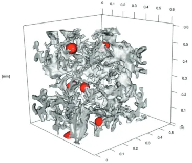
Compacted graphite (CG) is regarded an intermediate between LG and SG in many regards. Owing to its worm-like appearance on a cross section, its shape is often referred to as vermicular. In three dimensions is has the appearance of irregularly shaped flakes which branch and twist as they extend outwards, as can be viewed in Figure 3.
Figure 3. 3D model of compacted graphite iron, obtained using X‐ray microtomography. Spheroidal graphite particles are highlighted in red [188].
It develops under a narrow range of intermediate conditions between lamellar and spheroidal [119, 143]. The production window is also transient, making stable production challenging [143, 144]. A variety of additions have been reported to extend the production window, e.g. additions of Ce, Al and Ti, however the mechanism is unclear [145, 146]. Multiple material standards have been developed, all of which tolerate a rather generous amount of spheroidal graphite present in the structure, e.g. 20% area fraction in the case of ISO 16112 [147].
Building on the understanding of spheroidal graphite, surfactants like O and S are believed to play an important role also in CGI [119, 144]. In contrast to LG and SG, where the interfacial energy between melt and graphite is lower for the prism and basal plane respectively, CG has been found to occur when the two are near equal. This has led to the expectation that CG is characterized by growth on both prism and basal plane. Further development of this idea has been made by utilization of general crystal growth theory [119]. It has been argued that surfactants promote growth along the prism plane by adsorption on the prism plane [119]. TEM graphs have been presented in support of this, showing that LG displays a lower degree of faceting [119]. In the absence of impurities, the low mobility of the prism plane means that graphite must grow at larger undercooling, promoting growth along the basal plane through spiral growth mechanism [119]. Observations regarding the substructure and preferred growth direction of CG are mixed, including claims of basal plane growth, prism plane growth and amorphous carbon, however growth on the basal plane appears to be more common [10, 132, 148]. Recently it has also been proposed that CG is composed of a substructure of small platelets [132, 139, 149, 150]. Graphite in CGI has been observed to grow as spheroids prior to interaction with γ, reinforcing the evidence for growth on the basal plane [144, 151, 152].
Upon interaction with austenite, the spheroids become partially incapsulated by graphite and degenerate into compacted shape [144]. This indicates that, besides preferred growth direction, the interaction between G and γ is important to the development of CG. Similar to LG-γ eutectic the CG grows coupled with γ in roughly spherical cells. The graphite inside the cell is interconnected, branching out from a center with edges in contact with the melt [144, 151, 153].
Some observations suggest that the γ is the leading phase during growth of the CG-γ eutectic cells, unlike the LG-γ eutectic where the graphite edge typically protrudes into the liquid ahead of the γ [152]. In some cases, the austenite protrudes to such an extent that only a small channel is observed to connect CG to the liquid, particularly during later stages of solidification [151, 152]. Trace elements rejected into the liquid have been observed at elevated concentrations in the channels. This has led to the suggestion that the reason certain elements tend to widen the process window for CGI is that they help maintaining the connection between liquid and graphite by lowering the freezing point of the liquid channels [152].
Cooling rate has a pronounced effect on graphite morphology in CGI, frequently observed as high nodularity in thin sections [154]. This can to some degree be explained by the shorter solidification time, leaving less time for fading of the spheroidization treatment [144]. However, high cooling rate also leads to high undercooling. SG-γ type eutectic has been proposed to be favoured by high undercooling, by promotion of spiral growth mechanism on the basal plane [119, 155, 156]. High undercooling has also been proposed to favour austenite growth,
facilitating encapsulation of the graphite [144]. The idea that large undercooling promotes SG-γ type growth is also motivated by cooling curves, typically showing low temperatures and weak recalescence for SGI [144]. However, the minimum temperature before recalescence is under certain conditions lower for CGI than for SGI [153].
The influence of cooling rate appears to be complex. First of all, slow cooling means more time for the spherodizing and inoculation treatment to fade. However, it also affects the undercooling at which the eutectic grows, which, according to the coupled zone theory, plays an important role to the collaboration between G and γ.
At the periphery of CG-γ cells, the CG tips may sometimes be thick, giving the appearance of spheroids. This has been interpreted as the CG edge having been overgrown by γ and lost its contact with the melt, meaning further growth has to occur by diffusion through a layer of γ similar to SG-γ [146, 153].
Subpopulations of eutectic cells
The size distribution of SG in eutectic and hypereutectic SGI often include more than one mode. In hypereutectic SGI a mode of larger spheroids may be explained as primary graphite, where the larger size is relates to the prolonged growth in direct contact with the liquid [62]. Sometimes, the distribution close to the surface of the casting is reported to be unimodal, while the interior is bimodal [157]. Apart from their size, the set of larger nodules is associated with higher concentration of Si and a shell of ferrite, while the set of smaller nodules are reported to more frequently be embedded in pearlite, display little or no aura of elevated Si concentration, and be located in regions late to solidify [125, 158, 159]. A third, smaller mode has been reported to appear in heavy sections [64, 157]. The phenomenon of different size groups of eutectic cells is not exclusive to SGI. Bimodal size distribution of nodules has been observed in CGI [159, 160]. A set of smaller LG-γ eutectic cells has also been recognized in LGI [69, 161-163]. A larger set of LG-γ does not relate to primary graphite as this is expected to form easily recognized large straight graphite plates. Instead the smaller subpopulation is proposed to be explained by a secondary nucleation event during a late stage of solidification. The nucleation is proposed to occur due to impingement of the eutectic cells, which increasingly limits the solidification rate [161]. The last liquid then cools due to the low release rate of latent heat, leading to undercooling exceeding the previous maximum level, activating additional nuclei [161]. Segregation of solute elements is also considered an important factor to predict secondary nucleation events since partitioning causes the equilibrium eutectic temperature to shift considerably near the end of solidification [162].
MICROSEGREGATION
During freezing of alloys, the solute elements distribute between the solid phases and the liquid. This process is called solute partitioning. The ratio of the amount of solute on each side of an interface of a pair of phases which are in equilibrium is called an equilibrium partition coefficient [164]. The equilibrium partition coefficient depends on temperature, pressure and curvature of the interface [164]. If the system is in equilibrium, the concentration of the phases are easily found using an equilibrium
phase diagram and the amount of phases are found using the traditional lever rule [165].
In most practical solidification scenarios, equilibrium does not hold in the bulk of phases, only at interfaces [166]. The low mobility of solute in the solid means that concentration can only equilibrate with the liquid locally at the interface. This causes the concentration in the liquid to diverge and leaves concentration gradients in the solid. Under the assumption of zero mobility in the solid, infinite mobility in the liquid, equilibrium over the interface and a constant partition coefficient, the evolution of concentrations in solid and liquid can be estimated using the Gulliver-Scheil equation [167, 168]. Under similar assumptions, more advanced calculations can be made for multi-component, multi-phase systems by coupling to thermo-dynamic modelling [169].
In many cases, however, a small amount of diffusion does occur in the solid, meaning the reality falls somewhere between equilibrium and the Gulliver-Scheil case. Accounting for finite mobility in solid or liquid is more complicated since it requires knowledge of factors like solidification time, diffusion rate, diffusion path length and crystal growth rate, making it necessary to combine it with some level of microstructure modelling [170]. For finite diffusion rate in the solid, the solute profile is subject to homogenization, which leads some solute to diffuse back across the interface, a process called back-diffusion [165]. Several analytical models exist for predicting back-diffusion during dendritic growth, making various assumptions about e.g. morphology and interface velocity [165]. These are valid until the onset of the eutectic, but not for back-diffusion occurring during eutectic solidification. For finite rate diffusion in the liquid, solute profiles develop ahead of the growing interface [171]. In this case an effective partition coefficient is useful to define as the ratio of solute concentration in the solid close to the interface over the solute concentration in the liquid far away from the growing interface where the concentration can be assumed uniform due to convection [164, 171]. Unlike the equilibrium partition coefficient, the effective partition coefficient also depends on solute transport in the melt [171].
For extreme crystal growth rates, equilibrium over the interface is broken, because there is not enough time for solute to partition, and ends up locked in the crystal lattice, a phenomenon called solute trapping [172].
Experimental and theoretical work on Fe-C-X suggest that the tendency of graphitizing alloying elements to concentrate in the solid austenite during solidification of cast irons relates mainly to their interaction with C [22, 173]. For low carbon contents, i.e. steels, graphitizing and carbide stabilizing elements both concentrate in the melt during solidification [22, 173]. For increased carbon contents, the repulsive interaction between graphitizing elements and C forces them out of the C rich melt and into the γ [22, 173]. Conversely, the attractive interaction of carbide stabilizing elements with C pulls them into the C rich liquid, lowering their partition coefficient [22, 173].
In practice, cast irons contain a large number of alloying elements, making partitioning more complex. Segregation was investigated in SGI, noting that the areas around SG was enriched with Si, Ni and Cu, while the last-to-freeze areas were enriched with Mn, Mo, Cr, Va, Ti and Pb [82]. In a poorly inoculated SGI, larger regions of low Si were found and coincided with regions of high Mn concentration [82]. In
normally inoculated SGI, such characteristics were limited to two smaller regions. The slow growth mode of the SG-γ eutectic and poor inoculation was proposed to contribute to stronger segregation. In a later study on SGI with a solidification time of about 30 seconds, the effective partition coefficients were measured and found to correspond roughly to those measured and analytically determined for ternary Fe-C-X alloys [174]. The measured evolution of Si, Mn, Mo, and Cr in the solid close to the S-L interface versus fraction solid was found to agree roughly to solute profiles calculated by application of the measured effective partition coefficient to the Gulliver-Scheil equation. Ni and Cu displayed worse agreement. The assumptions of zero diffusion in solid and instant mixing in the liquid were found to be reasonable for the conditions of the experiment. Later work by the same authors brought further support to these conclusions [175]. Solute profiles of Si and Mn in austenite as a function of fraction solid was estimated using EPMA in an SGI quenched soon after solidification was finished and compared to simulated profiles. The simulation made the same general assumptions as the Gulliver-Scheil model but applied a temperature and composition dependent partition coefficient for Si and a composition dependent partition coefficient for Mn. The simulated profiles agreed reasonably with the measured profiles.
KNOWLEDGE GAPS
The above literature survey shows that much is already known about solidification of Cast Iron, however some areas remain unclear.
Most research has revolved around the eutectic stage of solidification, meaning topics related to the dendritic austenite structure and its influence on the later solidification is still rather unexplored. The studies on the dendritic structure also mainly focus on hypoeutectic LGI. The development of the structure in CGI and SGI, which are typically near or hypereutectic, is not well known. As has been pointed out a long time ago [71], the primary reason for this appears to be that it is not easily observed in the final structure and knowledge on how to reveal and characterize it is scarce. Lack of knowledge on how to characterize the structure has led to many subjective and ambiguous descriptions, making it difficult to interpret and compare earlier work. The dendritic structure has been studied in other alloys, but this knowledge is rarely utilized in cast irons. Recently, some useful parameters related to the structure were introduced [95], however, the spread of their use has been limited due to lacking understanding of their relevance and practical means to measure them.
The spheroidal graphite particles in SGI have received extensive attention, however the same cannot be said for CGI, even though they often make up a considerable part of the structure. A recent research project related to shrinkage porosity formation in CGI indicated that the defects may be associated with a higher volume fraction of SG, in particular, a subpopulation of smaller SG which seemed to have formed at a late stage of solidification. This has contributed to a raised interest in their nature and role in the material as well as the conditions in the last melt to solidify. It is commonly stated that nucleation of graphite in SGI continues throughout solidification. For CGI nucleation is regarded discrete due to the strong recalescence observed on cooling curves. It is therefore suspected that the proportions of SG versus CG dictate the solidification kinetics which may interrupt continuous nucleation, or reactivate discontinued nucleation. Nodularity is for this reason expected to influence the size