M
ÄLARDALENU
NIVERSITYS
CHOOL
OFI
NNOVATION, D
ESIGN
ANDE
NGINEERINGV
ÄSTERÅS, S
WEDENThesis for the Degree of Bachelor in Computer Science - DVA 331
VR/AR and Digital Twin for improved
visualization of overview and debugging
of live hardware in next generations
industry.
Kristian Jansson Room
krm17002@student.mdh.se
Joakim Karlsson
jkn17010@student.mdh.se
Examiner:
Moris Behnam
Mälardalen University, Västerås, Sweden
Supervisor: Leo Hatvani
Mälardalen University, Västerås, Sweden
Author: Joakim Karlsson, Kristian Jansson Room Thesis Report
Abstract
This thesis describes the implementation of a Digital Twin tied to Virtual Reality environment that could, by easy means be expanded to Augmented Reality-solution. The field is of interest due to the fact that movement into Industry 4.0 puts the traditional operator in a new seat of work. Previous hands-on tasks are replaced with system monitoring and supervision roles. New interconnected industrial hardware allows for extensive data collection, while interactive technology like VR/AR helps monitoring live systems in completely new manners. An operator can overview and debug industrial systems while not even being in close proximity of the physical system. This provides the opportunity to increase the level of system information presented to the operator. The Cyber Physical Factory created by Festo was targeted to be represented as a digital twin. The question asked: What are
the advantages and/or disadvantages of monitoring and troubleshooting a Festo CP-Factory by means of a digital twin-driven visualization? proved to be extensive and the work included mapping of important factory data and DRM-research to find visual improvements between the provided solutions by Festo, and an implemented digital twin. The solution we produced focuses on overview and debugging and it connects to OPC-servers on each mapped module of the Cyber Physical Factory and acquires the data. This data can then be used to expand, test and debug previous sessions. Each real implementation of a factory has some type of logging of data, our solution allows visualization of those log entries as close to reality as possible, reducing the need to search databases for indications of problems. The Unity 3D created software also handles dynamic connections where the operator can modify which nodes to connect to in an intuitive way, this enables our software to abstract and modify information outside of the source code.
Author: Joakim Karlsson, Kristian Jansson Room Thesis Report
Table of Contents
1. Introduction 7
2. Background 9
2.1. Industry 4.0 9
2.2. Festo and the Cyber Physical Factory 9
2.3. Digital Twin 10
2.3.1. Early days of Digital Twins and their definitions 10
2.3.1.1. 2010 - 2012 NASA creates the Expression 11
2.3.1.2. 2013 11
2.3.1.3. 2014 - 2015 11
2.3.1.4. 2016 11
2.3.1.5. Post 2016 11
2.4. Industrial VR/AR 12
2.5. Open Platform Communications and Unified Architecture 12
3. Related Work 13
3.1. Festo and its VR/AR definitions. 13
3.2. Virtual Production Line -Virtual Commissioning (J.Persson, J.Norrman 2018) 14 3.3. Using Unity3d as an Elevator Simulation Tool (J. Polcar et al., 2017) 14 3.4. Benchmarking of existing OPC UA implementations for Industrie 4.0-compliant
digitalization solutions (H. Haskamp et al., 2017) 14
3.5. Digital Twin Based Synchronised Control and Simulation of the Industrial
Robotic Cell Using Virtual Reality (V. Kuts et al., 2019) 14
4. Problem Formulation 15
4.1. Question formulation 15
4.2. Extension upon Digital Twin definitions 16
5. Method 17
5.1. Festo Cyber Physical Factory 17
5.2. DRM 17 5.2.1. Criteria definition 18 5.2.2. Descriptive Study I 18 5.2.3. Prescriptive Study 18 5.2.4. Descriptive Study II 19 5.3. Research 19
6. Ethical and Societal Considerations 20
6.1. Engineers honor codex 20
6.2. Industry 4.0 and its ethics 20
Author: Joakim Karlsson, Kristian Jansson Room Thesis Report
7. Description of the work 20
7.1. Selecting the data protocol 20
7.2. Mapping the Physical Twin 21
7.2.1. Mapping CP-F-ASRS32 22
7.2.2. Mapping CP-F-BRANCH 22
7.2.3. Mapping CP-F-RASS 23
7.2.4. Logging the input 23
7.2.5. The settings file 24
7.3. Research phase 25
7.3.1. DRM: Initial Criteria and mappings 26
7.3.2. DRM: Iteration One, the metrics of the original solutions 27 7.3.2.1. Descriptive Study I: The existing solutions. 27
7.3.2.1.1. MES4 - The Desktop software 27
7.3.2.1.2. Factory attached Human-Machine Interfaces 28
7.3.2.1.3. General comments about MES4 30
7.3.2.2. Prescriptive Study 30 7.3.2.3. Descriptive Study II 30 7.3.3. DRM: Iteration Two 31 7.3.3.1. Descriptive Study I 31 7.3.3.2. Prescriptive Study I 31 7.3.3.3. Descriptive Study II 32 7.3.4. DRM: Iteration Three 32 7.3.4.1. Descriptive Study I 32 7.3.4.2. Prescriptive Study I 32 7.3.4.3. Descriptive Study II 33 7.3.5. DRM: Iteration Four 33 7.3.5.1. Descriptive Study I 33 7.3.5.2. Prescriptive Study I 34 7.3.5.3. Descriptive Study II 34 7.3.6. DRM: Final Iteration 34
7.3.6.1. Final Descriptive Study I 34
7.3.6.2. Final Prescriptive Study 35
7.3.6.3. Final Descriptive Study II 35
7.4. The implemented Research: Final Software 36
7.5. AR complement and its potential 37
Author: Joakim Karlsson, Kristian Jansson Room Thesis Report
8. Results 38
8.1. Comparing the solutions with regards to debugging and overview 38
8.1.1. Ease of use and overview 38
8.1.1.1. Feed forward 38
8.1.1.2. Complete Picture of a live system 39
8.1.2. Error handling 39
8.1.2.1. How does the solutions flag Errors 39
8.1.2.2. Error intuition and if they are easy to miss 40
8.1.2.3. Clarity in how to recover 40
8.1.3. Information Representation 41
8.1.3.1. Access and overview of data 41
8.1.4. Design (visuals) follow up and improvements upon the previous solution 42
9. Discussion 43
9.1. The strength that derives from digital twins 43
9.2. Discussion around the OPC solution and its logging 44
9.3. Discussions with regards to debugging and overview 45
9.3.1. Discussing ease of use and overview 45
9.3.2. Discussing Error handling 45
9.3.3. Discussing Information Representation 46
9.3.4. Discussing the solution design (visuals) 46
9.4. VR and AR as technology 47
9.4.1. Pros/Cons of VR as improvement upon workflow 47
9.4.2. Pros/Cons of AR as improvement upon workflow 47
9.4.3. VR/AR, should it be used? 48
9.5. Reconnect to the overarching question 48
10. Conclusions 49
10.1. Purpose of the question 49
10.2. Overview of the thesis and its work 49
10.3. Summation of the results and its impact 51
11. Future Work 52
11.1. Complete mapping of the factory 52
11.2. Playback tools 52
11.3. Audio 52
11.4. Animation 53
11.5. Expand the settings functionality 53
11.6. Build Tools 53
11.7. Complete tool-suite for creating generic digital twins 53
11.8. Holographic work, the real power of the technology 54
11.9. Create a duplex connection between the twins 54
Author: Joakim Karlsson, Kristian Jansson Room Thesis Report
Table of Resources
Figure 1, Festo modules 10
Figure 2, Festo real size 10
Figure 3, The DRM research process 17
Figure 4, Festo pure DT 57
Figure 5, the Mitsubishi arm used by RASS 57
Figure 6, The Lightboard 58
Figure 7, CSV file 58
Figure 8, MES4 - Main window of the MES4 software 59
Figure 9, MES4 - Watch tables 59
Figure 10, MES4 - The watch table dropdown menu 60
Figure 11, MES4 - Historical data 60
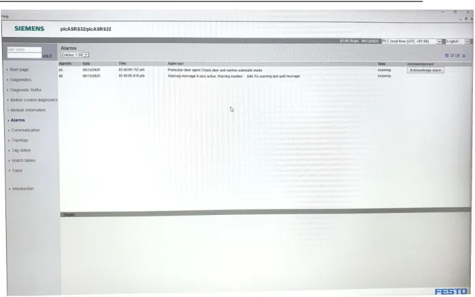
Figure 12, MES4 - Error screen 61
Figure 13: ASRS32 - Settings of the gripper arm 61
Figure 14, ASRS32 - Storage 62
Figure 15, ASRS32 - Belt overview 62
Figure 16, ASRS32 - Stopper 1 and Stopper 2 63
Figure 17, ASRS32 - Error screen 63
Figure 18, CP-F-Branch - Measure attachment laser-view 64
Figure 19, RASS - Main overview 64
Figure 20, RASS - Robot Arm. 65
Figure 21, DRM 1- Menu 65
Figure 22, DRM 2 - Implementation showcase 66
Figure 23, DRM 3 - Error and readability improvements 66
Figure 24, DRM 3 - BRANCH Mixed-Mode 66
Figure 25, DRM 3 - BRANCH Overview-Mode 67
Figure 26, DRM 3 - BRANCH Digital Twin-Mode 67
Figure 27, DRM 3 - ASRS32 Mixed-Mode 67
Figure 28, DRM 3 - ASRS-32 Top Abstract 68
Figure 29, DRM 3 - ASRS-32 Overview-Mode 68
Figure 30, DRM 3 - ASRS-32 Off 68
Figure 31, DRM 3 - RASS Mixed-Mode 69
Figure 32, DRM 3 - RASS Overview-Mode 69
Figure 33, DRM 3 - RASS Off 69
Figure 34, DRM 4 - Color-schemes 70
Figure 35, DRM 4 - Error Overview 70
Figure 36, DRM 4 - Carrier Card Comparison 71
Figure 37, DRM 4 - Stations 71
Figure 38, DRM 4 - Minimap overview 71
Figure 39, DRM 4 - VR Minimap 72
Figure 40, DRM 5 - Station and Carrier updates 72
Figure 41, DRM 5 - Thematic implementations 73
Author: Joakim Karlsson, Kristian Jansson Room Thesis Report
Figure 42, DRM 5 - Minimap expanded 73
Figure 43, DRM 5 - Colour updates 74
Figure 44, Final - Factory in Overview-Mode 74
Figure 45, Final - Factory in Digital Twin-Mode 75
Figure 46, Final - RASS Order overview 75
Figure 47, Final - Belt movements 76
Figure 48, Final - Feed example 76
Figure 49, Final - Safety door open 77
Figure 50, Final - Minimap function in VR 77
Figure 51, Final - Environment interactions 78
Figure 52, AR - Android Connecting to OPC 78
Figure 53, AR - Android Connected to OPC 78
Figure 54, AR - In-simulation menu 79
Figure 55, HoloLens - Example 79
Figure 56, MES4 - ASRS32 PLC overview 79
Figure 57, MES4 - Communication page 80
Figure 58, MES4 - The utility page 80
Figure 59, MES4 - The pallets view 81
Figure 60, RASS - Stopper 1 81
Figure 61, RASS - Stopper 2, Robot station 82
Figure 62, RASS - Divert arm 82
Figure 63, RASS - PCB BOX 83
Author: Joakim Karlsson, Kristian Jansson Room Thesis Report
1. Introduction
This thesis describes the implementation of a Digital Twin solution tied to Virtual Reality that in easy means could be expanded to Augmented Reality-solutions, which we argue is the future for machine-human interactions. This is an interesting field due to the fact that movement into Industry 4.0 now allows us to map and understand live systems in completely new manners, allowing an operator to even overview and debug hardware in completely new ways, while not even requiring the operator to be close to a physical factory. As VR/AR technology gets cheaper and better we can actually use it in real industrial solutions to improve upon work-factors. Previous generations of the technology were not powerful and cheap enough but today the technology is even widely used by the general public, the industrial solutions are still in its early phases where most solutions are still only theoretical, we aim to implement these theoretical aspects in a short timespan. We used a module based system available to us at MITC (Mälardalen Industrial Technology Center based in Eskilstuna, Sweden) called Festo Cyber-Physical-Factory. The hardware and its platform is developed for research and education which was perfect for work like this thesis.
Digital Twin as an expression has gained interest the last 5 years in an increased manner but NASA brought the expression to the public attention already in 2010. Previous work tries to represent reality as close as possible and even allow for interaction between physical and digital twins. Festo already has a Digital Twin implementation in VR called CIROS but it uses strict definitions of DT-solutions. We aim to improve upon this software in a more generic fashion, applicable to most systems where we can read and understand data in a better fashion. We instead focus upon altering reality if it is incremental towards understanding, overview and debugging by abstracting the physical system in ways not always possible with strict definitions of DT-systems. Festo also provides an AR application usable with handheld devices as an example, we never tried to implement something better but instead used our work as proof of how the technology could be used instead, since the usage of a hand-held device will hold the industrial operators work-flow back. While it certainly works as a quick overview of smaller parts of the system, we instead want to aim higher and revolutionize the industry towards Augmented Industry where machine and human becomes more connected and we need better solutions as explained in this work.
We found interesting related work in our literature study: The thesis “ Virtual Production Line -Virtual
Commissioning” explains the development of a digital twin in welding using Unity3d together with OPC communication but the work does not include the VR/AR aspect. In an attempt to find benefits in simulation applications, “Using Unity3d as an Elevator Simulation Tool” investigates the possibilities
of using Unity3d as a modeling tool for elevators versus a Discrete event simulator. In the field of industrial data communications, the paper “Benchmarking of existing OPC UA implementations for Industrie 4.0-compliant digitalization solutions” found out to be useful in our search for a OPC-UA framework to be used in Unity3d. Our definition of digital twin does not allow for controlling the physical twin, the work “Digital Twin Based Synchronised Control and Simulation of the Industrial Robotic Cell Using Virtual Reality” however, researches the possibility of controlling an industrial robot through a digital twin.
This report and our work aims to give examples of and prove how real Digital Twin solutions can work and what they should focus upon when being created. This means any organization that has I4.0 compatible hardware, mainly tied to production, will find the work done here incremental towards how their solutions could be developed, especially if it is tied to overview and error handling. And by implementing our ideas we should see improvements to productivity tied to understanding of live hardware (or previous/saved runs) as well as decrease fatal downtime of real factories.
The question asked:What are the advantages and/or disadvantages of monitoring and troubleshooting a Festo CP-Factory by means of a digital twin-driven visualization? aimed to map important backend data and then improve upon the aspects as we presented above. The reason the question is relevant is because we need to define the impact of DT-solutions and their pros and cons before any organization is willing to invest in the technology.
Author: Joakim Karlsson, Kristian Jansson Room Thesis Report
We first defined and mapped the backend systems (Festo modules) and then used DRM-research to find improvements between the current solution, called MES4, towards our implemented twin. The solution we produced focuses on overview and debugging and with that perspective we also analyzed the current solutions that come with the Festo-CP-F system. Our software manages to connect to OPC-servers on each mapped module and save the data. This saved data can then be used to expand, test and debug previous sessions which is powerful. Each real implementation of a factory has some type of logging of data, our solution allows visualization of those logs just as close to reality as possible via VR and the Digital Twin, no more searching datatables for explanations after fatal errors. The Unity 3D created software also handles dynamic node-connections where the operator can modify which nodes to connect to in an intuitive way, this enables our software to abstract and modify information outside of the source code.
We found in our work that the impact of a DT-solution can be great if it is developed with the right focus. Our work focus upon overview, understandability and error clarity so that is the perspective we developed from and argued in this report. We also found some real technical improvements over the original, MES4, solution. A VR solution tied to DT’s is a great way to simulate the real world and this can be important for replays of captured sessions, simulations of underlying data and test the security and other aspects of systems without ever touching the real twin. Also the impact of this technology in hazardous environments could be substantial, especially if we allow a connection back to the PT from the DT so the operator can steer and operate from a safe environment. Our work also arguments that AR as an technology could be revolutionary “on the work floor” of real implementations if it is tied to holographic lenses where we can expand upon reality in a non intrusive way, if it helps workflow, understandability and productivity.
Author: Joakim Karlsson, Kristian Jansson Room Thesis Report
2. Background
Companies are interested in discovering possibilities and advantages of technologies such as VR/AR for industrial applications. We aim to improve upon these in new ways of thinking by adding a digital twin for debugging and overview that can be interacted with. The industry is looking into digital twins to improve various aspects of manufacturing but it is still in early stages. The following sections describe some important terms to fully understand this thesis work. First the Industry 4.0 paradigm is described which is in the field of this thesis. Later we are inspecting the components of Industry 4.0 and several focus points emerge like the Cyber Physical Systems, Digital Twins and other means like VR/AR that play a significant role. As one of the key factors of Industry 4.0 is connectivity, we describe the communications standard OPC because this is frequently available in the industry. Below follow some important topics that let us achieve the creation of an interactive digital twin in a virtual and augmented environment.
2.1. Industry 4.0
First defined at Hannover Messe, Germany in 2011 [1],[2], the overall industrial trend is aiming for its next phase, called Industry 4.0, where factories are intertwined with computers and each other to a greater degree for improved construction. The focus now lies in increased access and control with the help of communication between all parts of an industrial environment, all in real time. This is the next step in our industrial evolution and thus work towards this field is important. Smart factories can and will use data to learn and predict machine's needs for maintenance and costly repairs. This means that a production flow also can be supervised to a greater degree where every component could report its status in the production chain. We strongly believe our work could be beneficial towards this part of Industry 4.0.
Industry 4.0 also stands before a great problem regarding security [3], since these systems are often connected with each other through IIoT(Industrial Internet of Things) they are vulnerable to outside attacks. Scientific research promotes [3] that digital twins could help prevent disasters by preventing and testing these problems with digital counterparts, without affecting a real system. Thus, our research is important to the future of these major systems and Industry 4.0´s success.
2.2. Festo and the Cyber Physical Factory
Festo is one of the companies that is leading in digitalization together with physical products. Their primary focus lies in systems connected to education and research and achieve this by developing Industry 4.0 and smart solutions.
Cyber Physical-Factory (CP-F) is a Cyber Physical System (CPS) that is developed by Festo and is a fully functional system where the customer can build a factory on a lesser scale [ Figure 1][Figure 2] for research and learning purposes. It is module based and is customizable to the user's needs. The system uses conveyor belts to transport carriers, see [ Figure 58], towards different stations, as is common in production flows. The different module-roles range between anything from storage units, drilling connections, assembly in different stages, product control and transport between factories/modules via robots and all of these units do these tasks along with available sensor logic.
Author: Joakim Karlsson, Kristian Jansson Room Thesis Report
Figure 1, Festo modules:
Modules from Festo CP Factory. In this picture can we see how different robots send units between different modules [4].
Figure 2, Festo real size:
CP Factory in real scale to understand the size of the system [4].
2.3. Digital Twin
A Digital Twin (DT) as a concept is important for the upcoming discussions and will be our primary focus. The different perspectives of digital twins are widespread and thus we need to define our viewpoint, this is discussed in more detail in section 3.1and we make the definition in 4.2. The Digital Twin was created in the context of aerospace (NASA) in 2010 (finished by 2012) [1] and were first defined as: a multi-physics, multi scale, probabilistic simulation of a flying twin or system connected to the latest sensory data, physics models and historical data (not live). In 2012, the same year when the work was finished [1], new definitions arose and a new perspective, interesting to us, are the one for prognosis and diagnostics activities. The next big step for DT was in 2015 when [5] defined DT with more generic uses, it still targeted aerospace but the concept became interesting for other fields. In other words, over the last 5 years, DT’s has been more and more adopted as a topic in other fields, such as industry. This late development is one of the reasons for the many different perspectives. One should note that previous research was made before 2015 as explored in 2.6. The Digital Twin generally aim to mimic a real world system, the Physical Twin (PT), as close as possible for improved reality. It is often used for different simulations, such as aerodynamic simulations in aerospace to understand and improve upon how the physical system would behave in theoretical and real situations.
2.3.1. Early days of Digital Twins and their definitions
According to [1, Table 1. Definitions of Digital Twin in literature] the early structure of DT and previous work were:
Author: Joakim Karlsson, Kristian Jansson Room Thesis Report
2.3.1.1. 2010 - 2012 NASA creates the Expression
NASA defined DT in 2010 publically and its definitions were worked upon until 2012. They defined the system as a multi-physics, multi scale, probabilistic simulation of a flying twin or system connected to the latest sensory data, physics models and historical data. It was meant to specifically mirror the life of its flying twin. This made most of the following research first to focus on aerospace use-cases. Other work in 2012 saw DT as a cradle-to-grave model of an aircraft structure. Which means it was meant to map a physical system from its creation till its destruction. It included submodels of the electronics, the flight controls, the propulsion system, and other subsystems for complete mapping. Ultra-realistic definitions also arose tied to aircraft structure to make sure the system could handle mission requirements.
2.3.1.2. 2013
New definitions and areas were created which meant other fields began to see uses for digital twins as well. Cloud-platforms became coupled with DT-systems in research, in other words, real units. They were simulating the health and condition of the machinery inside the network systems and used analytical algorithms together with physical knowledge.
Research also went into ultra-high fidelity physical models where focus went into the materials and structures that control the lifespan of a system, mainly vehicles. Noteworthy in 2013 is also structural models that included quantitative, in depth, data of materials with high sensitivity.
2.3.1.3. 2014 - 2015
More work towards other fields gets done and more wider perspectives arrive, for example we have very realistic models of a process and its current state. Mapping also went towards system behavior in interaction with the environment in the real world. A more generic approach also gets defined, digital counterparts of physical products is a reality [5]. Aerospace also gets ultra realistic models mapped to each unique aircraft, generally this was not the case previously, this was combined with known flight histories. Research also came up with high- fidelity structural models, they mainly focused on fatigue damage and presented a fairly complete digital counterpart of the actual structural system.
2.3.1.4. 2016
Work similar to ours emerges from multiple sources, for example Internet of Things (IoT) gets integrated by [6] with virtual substitutes of real world objects. Focus was on communication and virtual representation of the objects on the other end. Together the IoT network made up networks of smart nodes creating a twin as a whole. Another focus incremental to our own definition were: digital representations of real world objects, but focus were on the real life objects themself [7]. In 2016 research also went into simulations of future states of systems, in other words trying to predict states and state-machines.
Finally CPS, Cyber- physical systems, gets focus by [8]. Virtual representations were in focus and Industry 4.0 is directly connected to the definition, along with CPS.
2.3.1.5. Post 2016
The work and positive sides of DT gets focus by a broader audience, today it is heavily connected to Industry 4.0 if we look at the industrial side of things. To map more work than those above after 2016 will be too broad for the target of this report, mostly due to the scale of work, both scientific research and implementations, that has been done. Instead we use Festos own sources for definition when they ask the question if their digital system, CIROS, is a digital twin or not (see 3.1below). We also want to note that we can only find CIROS as the closest work available compared to our problem, especially connected to Festo assets.
Author: Joakim Karlsson, Kristian Jansson Room Thesis Report
2.4. Industrial VR/AR
According to the principles of Industry 4.0, see 2.1, factory communication is not limited to the machine to machine field only [9]. The human resources and knowledge can be further strengthened by taking advantage of wearable technology such as Virtual Reality (VR) headsets or handheld Augmented Reality (AR) powered devices like smartphones, tablets or holographic headsets. Both VR and AR are considered key components of the Industry 4.0 paradigm for training and visualisation [9]. VR transfers the operator to a virtual world that can be completely modeled to the current applications needs. With a headset the user can explore the environment in a safe way that can be used for many different scenarios such as for simulation, monitoring, interaction or educational purposes. This technology can be a great help when for example investigating future investments. The layout can be built virtually for testing and simulations which would allow for detecting flaws that could be extremely costly to fix afterwards.
The AR technology can be used to project digital content in relation to the physical world. A screen from a smartphone, tablet or smart glasses acts like a see-through tool that renders this digital content on top of what the user sees. This can be useful in industrial applications where someone might need to find information that is not naturally available on site in a factory for example. That can be assembly instructions for some part of machinery or a blueprint that can be displayed in direct relation to the part itself with interactive information. Also AR technology can be used to visualize information about the current state of machinery that is not easily available in the real world since AR won't adhere to the rules of the real world (time, space and gravity for example).
2.5. Open Platform Communications and Unified Architecture
Open Platform Communications (OPC) is a standard adopted by the industrial automation business, especially in Europe, for secure and reliable communications [10] based on the TCP protocol. The standard is maintained by the OPC Foundation and is built upon a series of specifications set by the members of the foundation, more specifically vendors, end-users & developers. Some of the specifications describe the communication between server/client or server/server, while others describe the access to real time-data/historical-data or the monitoring of changes/events in a network. In the beginning the OPC standard was restricted to the Microsoft Windows platform but has developed into a completely platform-independent standard. This is of high necessity for the further use of the standard because of the different equipment and embedded devices used in industrial applications. OPC-UA (OPC Unified Architecture) is a protocol based on a client/server architecture. Because it is platform independent, any client can access any server regardless of the system it is based upon. A server can collect data from its underlying sensors in any way it likes and then this data is available to clients through the OPC protocol. The protocol supports the auto discovery of servers in a specified network as well as the data it supplies for a client to browse. A client can place subscriptions on particular parts of the data to be notified on specific intervals or on specified events or changes. The OPC-UA protocol leverages a wide range of security features, where some are the use of client/server authentication certificates, message signing and session encryption.
Author: Joakim Karlsson, Kristian Jansson Room Thesis Report
3. Related Work
Related work will present our solution in comparisons between previous work done in the same field. We will begin with Festos current systems and how they define their products compared to research in
3.1below, the chapter then brings up and discusses other research and connects our work towards each one of them.
3.1. Festo and its VR/AR definitions.
We bring up this section under related work since Festo has two implementations themself that our work needs to be compared with, CIROS [11] and its AR-app are Festos own approach to the DT’s evolution. How they compare themself towards research and which definitions their work adheres to is important to understand how to relate where our work fits in a bigger picture, especially compared to Festos own solutions that are closest to ours.
As touched above, Festo provides their own implementation towards AR functionality that allows for displaying information of the running modules of the CP-F such as actuator and sensor states. It can also be used for visual guidance in commission of the modules [12]. This targets handheld devices and is optimized for tablets. The vision for the AR discussion around our system is to overview a greater part of the CP-F at once in real time and for this we target devices that are less disruptive of the monitoring workflow, like smart glasses or the Microsoft HoloLens [13].
Festo also provides a system called CIROS (Computer Integrated Robot Simulation) [11] that focuses on teaching the CP Factory system via simulations in VR environments. CIROS has live overview and visualization of the physical hardware, but it does not augment the visualization in any way, we instead aim to improve understandability via UI elements and tweak the twin for improved understandability at a glance, even if this means we have to add elements that does not exist or change parts in the real world. Our own definition of DT below in 4.2 allows us to improve upon reality which we took advantage of.
Our development of these AR and VR features were towards the connection between our digital twin and an identical physical system where we aimed to use parameters of the physical system to improve understandability of a running system, all in real time. Festo asks the question if the CIROS system is a digital twin, short answer is both yes and no depending on the criterias, they present them as:
• Bolton et al, 2018: “A digital twin is a dynamic virtual representation of a physical object or system ... using real-time data and interaction between them” [14]
• Söderberg et al, 2017: “Using a digital copy of the physical system to perform real-time optimizations” [15]
• Bacchiega, 2017: “A digital twin is a real-time digital replica of a physical device” [16] CIROS does not fulfill the first criteria but the other two they do, we will find below in our definition, in4.2, that we will only fulfill the last criteria in specific ways if we only focus on the same definitions as Festo do, which is logical in our situation since we want comparisons between the solutions.
Author: Joakim Karlsson, Kristian Jansson Room Thesis Report
3.2.
Virtual Production Line -Virtual Commissioning (J.Persson,
J.Norrman 2018)
The authors present their work in the Industry 4.0 domain with a digital representation of automation hardware [17]. Through the software RobotStudio by ABB and CoDeSys, a digital twin is implemented to verify and validate PLC code, before a physical station is commissioned. The paper is related to our work as it involves OPC data communication between a virtual and a physical representation of industrial machinery. Although their work is focused on the core connectivity for testing and simulation, whereas our work aims for enhanced supervision and debugging of a Festo CPF with the help of a digital twin. Also the tools for visualizing the digital twin differs as we use Unity 3D to build our virtual world to produce a more generic solution. The authors findings are that virtual commissioning is costly both in the way of gathering proper prior knowledge and the high time consumption.
3.3. Using Unity3d as an Elevator Simulation Tool (J. Polcar et al., 2017)
The paper describes the research regarding a virtual elevator simulator [18]. The work is related to our research in the sense that the simulator model is developed using the Unity3d game engine just as the virtual simulation in this paper. Research is performed to find out if Unity3d can be suitable to create a simulation model compared to traditional Discrete event simulation tools (DES). The tool is purely a simulator and no data from a physical counterpart is captured and processed, which differs from our work in that way. The authors found that the simplicity of using Unity's object oriented programming system and the use of 3D space, compared to DES is of great advantage for specialized situations. The steeper learning curve and price range of DES tools could be a key financial factor in this decision. Although for the overall situations DES found to be the preferred simulation modeling tool.
3.4.
Benchmarking of existing OPC UA implementations for Industrie
4.0-compliant digitalization solutions (H. Haskamp et al., 2017)
There are many different implementations of the OPC-UA protocol available for various programming platforms on the market. OPC-UA is considered one of the key technologies that complies to Industry 4.0 specifications. The authors of the paper are scanning the most common variants developed by corporations, foundations and private persons to compare their features and categorize them in paid vs free-of-charge groups [19]. Their findings indicate that there are comparable solutions in the two groups and some of the free implementations provide approximately the same features and documentation as the commercial ones do, or at least fulfills the criterias set up by the authors. This relates to our work because we needed to find an OPC-UA solution to develop a client in the C# language that is compatible with Unity3d. We found the “OPC UA .NET” solution provided by the OPC Foundation to be well suited to our needs.
3.5.
Digital Twin Based Synchronised Control and Simulation of the
Industrial Robotic Cell Using Virtual Reality (V. Kuts et al., 2019)
Digital twins can play a significant role in the automation industry in terms of simulations and training. The research [20] by Kuts et al. tries to find the benefits of using a digital twin alongside a physical robotic cell. The work aims for the possibility to not only monitor the physical counterpart in a Virtual Reality environment, but to also be able to control it by the means of the digital model. The DT was modeled in the Maya 3d software and the virtual environment set up in Unity3d. Part of the research aims to visualize movement data such as angles of the robotic arm and also some user directives are
Author: Joakim Karlsson, Kristian Jansson Room Thesis Report
visualized. The research concludes as a successful and viable solution which was tested by students and specialists in the robotic automation industry. The paper relates to our work because of the modeling tools used in the development process and the need to reduce model polygon density. The research also focuses on the digital twin concept in the same way as our work, although we do not find it necessary to control our physical modules through the virtual world in this stage of the research. The use of Virtual Reality is a common factor and because we strongly focus on the status and overview visualisations of our digital twin, these researches relate in regards to user interfaces in a virtual environment.
4. Problem Formulation
This chapter aims to present our research question, we will also structure the greater question into smaller segments in a roadmap manner in which the report later will answer. We also define our digital twin in this section since our problem also impacts definition of the twin, the expressions will be greatly intertwined.
4.1. Question formulation
This thesis aims to answer the following overarching question:
What are the advantages and/or disadvantages of monitoring and troubleshooting a Festo CP-Factory by means of a digital twin-driven visualization?
The more specific problem that we want to answer is if we can achieve improved overview and debugging by introducing a digital twin. We will also introduce VR and AR along with standard Desktop-solutions to the discussion for a wider perspective. Our question means we need to improve overview of the system and its data and we need to define how an optimal solution would look like and function. The Factory we want to focus on is the Festo Didactic system called Cyber Physical Factory and we aim to compare our solution to the overview system that is shipped with the product. We choose the system due to the fact it is built for research as ours and it can produce data towards generic discussions tied to Industry 4.0 and smart factories. As we will see in this reports upcoming chapters nothing will hinder our solution to be applied in a greater scale or problem, in other words a generic approach has been taken in discussions and implementations thanks to the Festo Cyber Physical System.
The visualization tag that comes with the overarching question means we have to look into and define the exact goals that is needed for improvements towards the targeted aspects. We also have to define and present how an effective solution would look like and function, as is common in DRM. This is directly tied to the pure visual and technical aspects of our solution which will be formed in the DRM-research, see 7.3. Visual aspects can be but not limited to: viewability of elements in the environment, improvements upon position of UI-elements or general clarifications and improvements. To finish we then present advantages and disadvantages compared to our result with the current solution that is shipped with Festo CP-F. This software is called MES4 which does not have a digital twin built in to the standard system that controls the hardware. The question and the discussion here is presented and used in the Results section when presenting the work, see Chapter 8for answers and discussions around the results and its impact can be found in Chapter 9.
Author: Joakim Karlsson, Kristian Jansson Room Thesis Report
4.2. Extension upon Digital Twin definitions
As were evident by Festo's own definitions, which are the ones this report build upon, of a digital twin presented in 3.1we could only achieve the definitions Bacchiega, 2017 named in our timespan and it is upon that definition we build our discussions. Compared to the other two we argue that our Digital Twin is not meant to alter or change any parameters of the Physical Twin, not even for enhancement which is the case in the other two sources presented in section 3.1. The data the DT produce could be used for improvement, but it's system should not affect the PT, this is for security reasons [3]. The primary purpose of our system is to improve readability of an active physical system, mainly for debugging and status viewing operations. Because of these aspects we needed to extend the digital twin defined by Bacchiega[16] and by doing so we could focus research and development so they were able answer our problems as described in 4.1.
This is how we describe the Digital Twin system used in this thesis research:
“A Digital Twin is a digital-system that is connected to a physical counterpart that is meant to mimic reality in greatest possible fashion and is meant to expand upon human-machine interaction. Integration of IIot (Industrial Internet of Things) is an important factor since it allows extensive, digital, knowledge about a physical system. Without the sensors that are connected via networking, the DT would not be effective compared to the real world due to the lack of data. Real time data should be in focus connected to overview and debugging as the goal is to keep the delay between physical and digital unit to be as low as possible, this is imperative. The digital system should also look like the physical counterpart when it comes to: scale, relation between modules (such as relation in space) and other “physical effects” that interact with the system, such as gravity or lighting which will improve realism in virtual realities. With realism in mind there is nothing holding the Digital Twin back to abstract away parts of the physical system that hinder understandability tied to overview. Examples of parts can be security attachments or window-panes that are meant to create a secure work environment as well as defending the hardware. A digital twin does not need these security-measures since the operator cannot get hurt or damage the system which means visibility in the virtual space can be greatly improved upon by removal of said parts. The physical twin will always represent the real world better than any mimicking twin and to make the Digital Twin as an available option it has to evolve and we need to improve upon factors increasing productivity. Thus should the software be able to represent the real world twin as close as reality as possible, but its focus for usability should improve upon important factors where it is necessary. This means that any Digital Twin should have more than one mode, at least two: Digital Twin Mode where we aim to be as close to reality as possible which is important for education, secondly we need an Improved Mode which is imperative for overview, debugging and understandability.”
As is apparent with our description we could in Digital twin mode achieve the definition of Bacchiega, 2017, see3.1. When using Improved Mode we will lose all these similarities since the system will not, to the greatest degree, be a replica towards reality, thus we extend the definition. Nothing is hindering the implementation by our extension to allow for other modes where the operator for example could control and impact the physical system from the digital counterpart, this would allow even more and stricter features to be available to us. We did not add this to our digital twin due to the security risks this connection would bring and our timeframe would not allow the implementation.
Even though we aim to use Virtual Reality (VR) and/or Augmented Reality (AR), we don't find that directly related to our description. Theoretically a 2D program tied to Desktop solutions can work under the same description as the one we plan to use, but work in VR would mean that the user could move around and monitor the system as one could in the real world. AR is where the user could use a handheld device to get more information about parts of the system, it would basically act like an overlay to the physical object when viewed through the device that could improve understandability of a live system. It would also allow for quick verification of system status to limit human introduced errors such as misplaced parts.
Author: Joakim Karlsson, Kristian Jansson Room Thesis Report
5. Method
This section aims to present how we tackled the problem via DRM and gives a short explanation of its methodology and what factors we used to define success or failure.
5.1. Festo Cyber Physical Factory
To answer our questions we used the Festo Cyber Physical Factory (CP-F), a training and research station with the capacity for real solutions, located at MITC in Eskilstuna. The CP-F is a module based system built with various units that are connected to each other. Each unit/module has its own state that can be monitored and data can be received from it via communications. This backend is the data we visualized for the user in a VR environment in relation to a digital version of the CP-F system provided. The virtual world was built in the Unity3d game engine that has extensive support for VR/AR development where our foremost focus was on VR but Unity3d enables quick and easy tools to convert these solutions to AR as well which enables a richer discussion. Previous literature was studied regarding VR and industrial implementations and how we could interact in these types of applications such as but not limited to: [21],[22],[23]. This work provided us with a good starting point in our research and we could define what we needed to focus upon tied to success parameters.
5.2. DRM
Our research was structured according to the Design Research Methodology (DRM) that suits this type of interaction design well [24, p. 112] as the research drives parameters as they surface via assumptions, experience and evaluations we focused these parameters upon optimal solutions based on overview and debugging. DRM is an iterative process and we needed to evaluate each step and then go back to reiterate the whole process and improve upon our previous solution where it was necessary, which means during all these iterations new functionality was added or revisited for evaluation according to our findings. The DRM emphasizes four steps to work towards a research result [25] that can be overviewed in [Figure 3].
Figure 3, The DRM research process
Author: Joakim Karlsson, Kristian Jansson Room Thesis Report
5.2.1. Criteria definition
Goal:
● Identify the aim that the research is expected to fulfill, and the project focus.
This means we first needed to map what we aimed to achieve by the DRM-research. Since our question aimed to focus upon overview and debugging we defined the goals with these two aspects in mind, see 7.3.1 for the targeted parameters as we defined them. Since our solution was meant to be compared to the existing desktop application along with the HMI-screens (Human Machine Interfaces) that are attached to each unit/module we also had to define problems with our definitions in mind versus the current solution, see 7.3.2.1 for this process.
In each iteration we got more information about the systems, problems and what we needed to focus on which is the proper strength of DRM as we could begin early and by previous faults correct and evolve the solution and our targeted parameters in 7.3.1and focus on design-parameters as defined in 5.2.3
below. This is the power of DRM since we can shift focus according to experience and the best practical solution as we do the research [25].
5.2.2. Descriptive Study I
Goals:
● Find factors that contribute to or prohibit a successful solution as defined in 7.3.1 and 5.2.3. ● Find details that can be used to evaluate design
Each of the first descriptive studies in each iteration took the previous iterations second descriptive study and tried to focus on improvement from the data produced. The very first iteration focused on the current solution shipped with the Festo CP-F and tried to define what was a success and what was a failure within the system tied to our initial criteria, see 7.3.1. This first step inspected the desktop solution (MES4) along with the HMI-interfaces that exist on each module.
5.2.3. Prescriptive Study
Goals:
● To develop a model or theory, based on the reference model or theory from the descriptive study stage, describing the expected improved situation.
● To develop prototype in a systematic way (Proof of concept)
The prescriptive studies in each iteration aimed to implement and try the improvements upon the data found in the first descriptive study. In other words the prescriptive phase is where the implementation and/or mockup work got done which in turn delivered valuable insights towards the second descriptive study that broke down the implementation studying success or failure, note that each of the parameters from the implementation we looked upon are the following:
1. Is the solution easy to use?
a. Here we focused on feed forward [26, p. 126] (Does the operator need to be trained in the software to use it?)
b. How easy it is to get a complete picture in one go? (Maybe there are multiple tabs with relevant information which might be a bad or good thing)
2. How clear does it handle errors?
a. In what way does the solution flag errors? b. Are they intuitive?
c. Are they easy to miss? (If operator has focus elsewhere) d. How do they look and can we draw any conclusions from that? e. Is it clear how can we recover from the errors?
Author: Joakim Karlsson, Kristian Jansson Room Thesis Report
3. How can the operator get information?
a. How quick/easy is it to navigate to the relevant information? b. Are there any problems with these navigations?
i. Such as the operator have to move in physical space to get the information ii. Not easy to use or great hierarchies to reach information
iii. Not clear what everything is
4. Does the solution design (visuals) follow and improve upon the previous categories in this list?
a. Color schemes i. Contrasts
ii. Are they easy to see in the environment? b. Orientation/transformation of menus and UIs
c. Are the relevant information grouped in intuitive ways? 5. What do we gain/lose from VR compared to desktop each iteration?
a. Does VR hinder the workflow or improve upon it?
5.2.4. Descriptive Study II
Goals:
● Find out if the prototype can be used for the intended situation(evaluation)
● Is each implementation a success compared to the focused design questions in 5.2.3? ● Are there any side effects present?
These stages are similar to the first descriptive study, but instead they focus on the improvements made in current iteration from the prescriptive study. The questions were the same as we used for development and we could use the data produced to check where problems still existed in each iteration. The deliverable at this stage was then used as data in the first descriptive study in the next iteration, unless we were finished with the research. Our study had five of these DRM iterations before we felt done with the result and had a strong proof of concept.
5.3. Research
All work needed to be grounded on current scientific data which also meant we needed to review and read up-to-date sources that touch improved design. The peer-reviewed sources we studied are mainly interaction design sources connected to VR and previous digital twin definitions. We also wanted to look at the human interacting with the system and how we can create applications that are better emotionally, we aimed to use [27] among others that discuss emotions connected to design-choices but there was no time to include these into the thesis and we recommend future work to look into these parameters as we believe them to be beneficial. What we mean with improved design and interactivity here is a better overview that could help prevent hazards (very clear warnings for example), new ways to interact with the hardware (for example focus on a small part of a greater system, abstracting all other information) and better feedforward [26] for new users [28],[29] together with an experience that feels natural. We also needed to investigate the OPC-UA protocol where the paper “Communication
Technology for Industry 4.0”[30] was useful to find more information and to define the metrics of the protocol compared to other popular communication protocols such as ROS, DDS and MQTT [30],[31].
There was a need for studying how certain areas of visual feedback are implemented for industrial machinery, in particular for the Festo CPF. We needed to review the solutions given for visual information like monitor positioning and content as well as light indicators with its colors and positions that the physical system at MITC is equipped with. Then we needed to compare our own result by listing what is better and/or what is worse with our implementation, all discussions grounded in current research with focus on our question: “To what degree could VR and/or AR connected to a digital twin visualize data to improve supervision and debugging of a Festo CP Factory in real time?”
Author: Joakim Karlsson, Kristian Jansson Room Thesis Report
6. Ethical and Societal Considerations
This is a brief section where we discuss some of the ethical effects our work could produce as we completed the research.
6.1. Engineers honor codex
If we focus on the Engineers Honor Codex [24, p. 20] we can't see that we, our work or its result could be in violation of these ethical guidelines. The closest to problems we could be is if this research would harm any of the corporations behind the technologies that we aimed to use such as MITC, Unity Technologies, Festo or Microsoft, but we find this highly improbable as our work finds the complete opposite to be more likely.
6.2. Industry 4.0 and its ethics
Our application aims to improve upon Industry 4.0 which is introducing some ethical problems. Since I4.0 could be replacing personnel-labour with robotics and digital solutions this work could have some catastrophic consequences if this were to come true. But with that said we argue that our section of I4.0 is made to improve upon the workflow for operators by increasing human-machine connections which should lead to that industry won’t need to replace them, but integrate humans with new digitized solutions that could change the possibilities towards a role of supervision and monitoring [9]. Thus we argue that our work and technical progress could be beneficial for the future industrial worker where jobs can continue, not become a replacement factor for organizations.
7. Description of the work
We had 3 major phases in the workflow, first of we mapped the systems, this proved to be the greatest hurdle and it took most of our time. Secondly we had the DRM research phase and lastly the conclusions and result phase.
7.1.
Selecting the data protocol
The modules of the Festo CP-F expose a lot of data about the states they are currently in. We needed this data to be transferred from the modules to our system to have a correct representation in the virtual world. Because there are a lot of different data transfer protocols such as OPC-UA, ROS, DDS [30],[31] and MQTT that are used in industrial communications, we needed to decide which one was best suited for our system. We found the answer would be the OPC-UA protocol, mainly because of the current system in place. To completely use another protocol would take too long to implement and bridge, but this was not a bad thing: The OPC-UA protocol is considered one of the cornerstones of Industry 4.0 [31] and because of this the Festo CP-F has extensive support for it. As this is an open protocol there are open source libraries available for us to take advantage of in our implementation [32], although it had to be tweaked a bit to work in Unity3d. Previous research [19] by H. Haskamp et al. guided us in the right direction to find suitable tools for developing the data communications part of our software targeting the .NET framework supported by Unity3d. All Festo CP-F modules have OPC-UA servers integrated into their Programmable Logic Controller (PLC) that we could connect to directly with our software which acts as a client to receive available sensor data. This reduced the complexity of our program because with other protocols we would have been forced to develop some kind of intermediate bridge to handle the data we needed to get a hold of. The clients (each module of our Digital Twin) signs up for subscriptions of every sensor on the server that provides data. Upon changes in the server the client gets notified via async protocols, and with the incoming data-stream we could incorporate the changes into our solution in any way we wanted.
Author: Joakim Karlsson, Kristian Jansson Room Thesis Report
7.2.
Mapping the Physical Twin
The mapping of the physical twin proved to be more extensive than we initially hoped. There is no extensive documentation over the MITC-specific implementation so we had to dissect every part of each module and its server nodes, for example does the ASRS32 contain nearly 2000 nodes. Our first thought was to subscribe to all nodes and then build a parser logging the important data. This would make saving/reading the data easier, see7.2.4, and we could just throw away the unneeded data, but as one might understand this was not a good approach. Due to the extreme amount of data that is produced the client won't get all data since both server and client are flooded (read/write in Unity must be done between frames). As an example, the ASRS32 produced 21 362 rows of data in a timespan of 14 minutes where we only needed a very small portion of the data and a lot of information was missing due to these bottlenecks as it needed to collect and write all data between engine ticks. The problem is also in the first few moments when we subscribe where the server will send the complete status of the system and this proved to be extensive and expensive. The reason we tried a “log everything” approach is to mitigate problems introduced when the user wants to produce the logs, they would have to subscribe to very specific nodes nested in a complex hierarchy and the work would quickly grow tedious, so a “log everything” approach would be easier for the user, but as we learned did not work. Due to the fact of the extensive nodes count we had to focus on fewer and relevant nodes and make sure to build our own OPC-client in the Unity-application. This would be beneficial since it could subscribe automatically to the correct nodes. This approach also lifted all work from the user when it comes to connecting and saving the logs, but this would be at the cost of maintainability and extensibility: to expand functionality the user would have to extend the source code. To mitigate this problem we landed in using a settings file with all paths and node names collected, see 7.2.5below for in depth explanations. The program will read these lines from a text file and parse them as subscriptions in our software. This approach was the best available and we did not need to map everything and the operator can add functionality as needed, outside of the source code. Note that the software will show the raw data stream and its values, no logic will respond to this data if it was to be added in this fashion. For that to work the source code needs to be altered, logically, see 11.5 for discussions around this problem and how to mitigate the problem. The settings file also enabled the software to be more dynamic in the other spectrum, imagine that the operator wants to abstract away unneeded nodes, they will just have to comment out a line in the document, and the system will not subscribe to the node.
Below we will look closer to the modules we chose to capture data from, the factory assets called: CP-F-ASRS32, CP-F-BRANCH and CP-F-RASS (Robot Assembly), see [Figure 4]. The nodes were first mapped and overviewed by an OPC-Client program called Prosys OPC UA Browser [33]. Since Festo could not provide up to date documentation of the MITC-Festo implementation we had to find the nodes we wanted manually by subscribing to them and view their data in real time. We then had the CP-F running and compared the subscribed values to the actions produced by the physical factory, with this method we could map values and it was of course not optimal. We should also note that on some parts of the physical factory there are labels of sensors that sometimes could be mapped to the OPC server which somewhat speed up our process along with Festo general documentation [34]. Sadly this documentation in some cases did not help us with logic or was wrong compared to the implementations. The hardest part was to find the error handling done by the modules, which was missing from documentation completely and we naturally wanted that data because of our softwares purpose, we had to manually find them. Most nodes work with string values (that can represent the normal data types such as booleans, floats or integers) and each error and sensor has its own node in the server. We can not to our current knowledge understand what all the different nodes, such as all errors, represent exactly but sometimes the naming and namespace of the node gives us a hint. We still present every error, but the more obscure ones will flag with its node name instead of having specific logic attached because of this documentation problem.
Author: Joakim Karlsson, Kristian Jansson Room Thesis Report
To sum the OPC-logic this means each error and all other data-nodes that have logic in the backend have to be manually subscribed to. This turned out to be a lengthy process and we can't always give a string output with an explanation to the user at this moment in time, but as an approximation we have mapped and created specific output for 90% of the subscribed data and to increase that number we will need an expert on the PLC logic in the MITC implementation, something we sadly not had time for and it is thus tagged as future work.
Also note that all software shipped with the solution such as MES4 and each module Human Machine Interface(HMI) will be presented in the DRM section of this report, see section 7.3.2and not in the mapping of each unit below. The upcoming sections will also shortly explain the purpose of each module and how they work.
7.2.1. Mapping CP-F-ASRS32
ASRS32 is the storage part of the MITC-factory, it handles all pallets, see [ Figure 59],and stores them in a hierarchical fashion. It has two loading stations where carrier ID and other data is read by an RFID sensor, the second of these stations will be triggered when an order is queued by the user. A carrier will stop and the arm of the unit will lift down one of the specified pallets (decided by the production-order from the MES4 software). When done the carrier will be released and transported to the BRANCH-module via the conveyor belt. On the first station the module will, with the help of the arm, lift back an empty pallet (or finished product if defined by the order instructions) when it arrives back after the completed production flow.
We chose to map the two loading stations and if there is a carrier present at them. These are composed of two nodes and they will also feed which carrier ID we have on these stations. We also mapped the nodes“diONo”, “diPNo”, “iOPos” and “iOpNo”. These will update with information when a station is loading/unloading a carrier and if a carrier has an order attached. “ iCarrierID” is reporting which carrier is present at the station. The OPC-server has different node sections (can be compared to folders in an file system hierarchy) and as an example we use “ dbTransport” to know in which direction the belts are moving, “dbRfidData” has the carrier data explained above and “dbError” has some (far from all) error-data that can affect the module. The Unit will also measure all raw sensors that are in the machine such as data to present what the gripper arm is doing, for example fetching a pallet. This is where the Festo documentation was of great help, we could use their own definitions of these nodes and add an explanatory text on the Machine UI (a feed showing what the machine is doing, all modules we mapped have them) thus increasing understanding of what the operator sees.
The module also has "dbAppCtrl"-specific data and in here we can find how the storage situation look like, but there are some underlying logic hindering these nodes from updating unless the physical system has a specific menu open (probably OPC functions), thus will our software read other lines instead of these nodes from the settings file defining what is present in storage from start, just as proof of concept. This should also be future work to dissect this problem and feed the data to our software dynamically.
7.2.2. Mapping CP-F-BRANCH
The CP-F-BRANCH is the module that handles input and output to the collective modules seen in [Figure 4]. It also has a CP-AM-MEASURE attachment that via two lasers checks if each carrier loaded with pallets have them at a correct distance (depth) and raises an error if the values are outside of the correct scope, this error is only visible via a light pillar on the unit presenting a green/yellow or red light depending on success. It also handles transport between the ASRS32 and the RASS along with output/input to and from the Robotino robot (CP-MR-C) which handles transport between the two Factory sections.