http://www.diva-portal.org
This is the published version of a paper presented at 2018 3DTV Conference: The True Vision
- Capture, Transmission and Display of 3D Video (3DTV-CON), Stockholm – Helsinki –
Stockholm, 3-5 June 2018.
Citation for the original published paper:
Ahmad, W., Palmieri, L., Koch, R., Sjöström, M. (2018)
Matching Light Field Datasets From Plenoptic Cameras 1.0 And 2.0
In: Proceedings of the 2018 3DTV Conference
N.B. When citing this work, cite the original published paper.
Permanent link to this version:
MATCHING LIGHT FIELD DATASETS FROM PLENOPTIC CAMERAS 1.0 AND 2.0
Waqas Ahmad
1, Luca Palmieri
2, Reinhard Koch
2, M˚arten Sj¨ostr¨om
11
Department of Information Systems and Technology, Mid Sweden University, Sundsvall, Sweden
2Department of Computer Science, Christian-Albrechts-Universit¨at, Kiel, Germany
ABSTRACT
The capturing of angular and spatial information of the scene using single camera is made possible by new emerg-ing technology referred to as plenoptic camera. Both angular and spatial information, enable various post-processing appli-cations, e.g. refocusing, synthetic aperture, super-resolution, and 3D scene reconstruction. In the past, multiple traditional cameras were used to capture the angular and spatial informa-tion of the scene. However, recently with the advancement in optical technology, plenoptic cameras have been introduced to capture the scene information. In a plenoptic camera, a lenslet array is placed between the main lens and the image sensor that allows multiplexing of the spatial and angular in-formation onto a single image, also referred to as plenoptic image. The placement of the lenslet array relative to the main lens and the image sensor, results in two different optical de-signs of a plenoptic camera, also referred to as plenoptic 1.0 and plenoptic 2.0. In this work, we present a novel dataset captured with plenoptic 1.0 (Lytro Illum) and plenoptic 2.0 (Raytrix R29) cameras for the same scenes under the same conditions. The dataset provides the benchmark contents for various research and development activities for plenoptic im-ages.
Index Terms— Plenoptic, Light-field, Dataset 1. INTRODUCTION
The seven-dimensional (7D) plenoptic function completely represents the light information within an observable space [1]. In the observable space, each light ray has a spatial posi-tion (3D), a direcposi-tion (2D), a time instant (1D), and a wave-length that reflects the color (1D) information. However, the present technology has physical limitation to capture a light field using the 7D plenoptic function. In order to reduce the dimensions of the plenoptic function, a set of constraints are used for the scene. The time information is not required when the scene is assumed static. The wavelength is sampled us-ing RGB channels, the wavelength parameter is constant for each color channel and can be omitted in the representation. Finally, an occluder free scene makes it possible to capture the incoming light rays onto a 2D plane instead of capturing light ray at each point of the space. Hence, the 7D
plenop-tic function is reduced to 4D when fixing the other parame-ters [2] and the captured spatial and angular information of the scene is referred to as light field (LF). The additional an-gular information has high significance since it enables var-ious post-processing application, e.g. 3D scene reconstruc-tion, refocusing at different depth planes, synthetic aperture, and digital zoom.
In order to record spatial and angular information, mul-tiple traditional cameras have been mounted on a camera rig and scene is captured at a single time instant, e.g. in [2]. The light field captured with a multi-camera system is referred to as sparsely sampled light field, and the pursuit of having densely sampled light field introduces a new camera technol-ogy. The spatial and angular information of the scene is cap-tured in the latter case using a single camera, also referred to as plenoptic camera. The idea of plenoptic capture was first introduced by Gabriel Lippmann in 1908 [3]. However, in 2006 the first commercial model was introduced by Ren Ng at Lytro [4]. In plenoptic camera, a lenslet array is introduced between main lens and image sensor that multiplex angular and spatial information onto a single image. Each microlens captures one position and multiple angular information and the model is referred to as plenoptic 1.0. In 2009, another version of the plenoptic camera also referred to as plenoptic 2.0 was proposed [5] with a slight change in optical design. Each micro-lens for such a plenoptic 2.0 camera captures a mixture of spatial and angular information of the scene. In 2012, based on plenoptic 2.0 camera model, Raytrix has in-troduced multi-focus plenoptic camera [6]. Micro-lenses with three different focal lengths were used to increase the depth of field of the captured LF.
Light field datasets are available online with different characteristics. Early contributions used multiple cameras as in [7] and [8], while more recent datasets contain LF images captured using the Lytro camera, as in [9], [10] and [11] for general light field processing applications. A dataset consists of synthetic contents [12] was also used as a benchmark for depth estimation schemes.
In recent past, plenoptic image processing has gained significant attention from the research community. Various competitions for plenoptic image compression were orga-nized [13, 14] and also novel methods related to 3D scene reconstruction and depth estimation [15, 16] were proposed.
However, in most of the experiments plenoptic images cap-tured with the Lytro camera were used due to the availability of Lytro datasets [9, 10]. In this paper, we present a novel dataset where the same scene under the same conditions was captured using Plenoptic 1.0 and Plenoptic 2.0, providing benchmark contents for LF applications and algorithms. The rest of the paper is organized as follows. The basic func-tionality of a plenoptic camera is explained in section 2. In section 3, the experimental setup is presented, and section 4 reports the contents of the dataset. The presented work is concluded in section 5.
2. THE PLENOPTIC CAMERA 2.1. Plenoptic camera 1.0
The plenoptic camera 1.0 has a micro-lens array (MLA) at the focal plane of the main lens as shown in Fig.1. The image be-hind each micro-lens contains the information about only one spatial point. The pixels in such a micro-lens image contain the angular information for the light passing this spatial posi-tion. The number of pixels in the micro-lens image defines the angular resolution, i.e. the number of different view points. The spatial resolution of the captured LF is determined by the number of micro-lenses.
Fig. 1: A schematic configuration of the Plenoptic 1.0 cam-era: the MLA is placed at the focal plane of the main lens, and image sensor is placed at distance fM LA(focal length of micro-lens). A point p is seen only from one micro-lens. The parameters correspond to the thin lens equationf1 = 1a+1b.
2.2. Plenoptic camera 2.0
In plenoptic camera 2.0, the micro-lens array is focused onto the image plane of the main lens as shown in Fig.2. Each micro-lens records a part of the scene so that a point is visible across multiple micro-lenses from slightly different perspec-tives, generating micro-images with overlapping areas. The traoff between the spatial and the angular resolution de-pends on the overlap between micro-images: lower overlap results in larger spatial resolution and vice versa.
Fig. 2: A schematic configuration of the Plenoptic 2.0 cam-era: the MLA is focused on the focal plane of the main camera lens. A point p is seen by many micro-lenses. The parameters correspond to the thin lens equationf1 = 1a+1b.
The multi-focus plenoptic camera produced by the Raytrix has an additional characteristic: the MLA contains three dif-ferent lens types with difdif-ferent focal length. This extends the depth-of-field of the captured LF, but introduces other chal-lenges in the manipulation of such images: each micro-image shows a different amount of defocus blur based on the depth of the scene.
3. EXPERIMENTAL SETUP
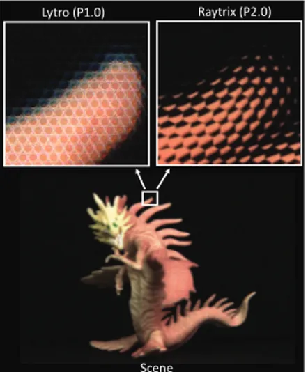
The dataset is captured using two different plenoptic cameras: Illum from Lytro and R29 from Raytrix. The former follows the plenoptic 1.0 model and the latter follows the plenoptic 2.0 model. Fig.3 shows a zoomed area of the scene captured with Illum and R29 cameras. The scenes selected for the dataset were captured under controlled conditions. Instead of using the natural light source, the scenes were captured in a closed room with two movable light sources. The cameras were mounted onto a multi-camera rig that was mechanically controlled to move the cameras with millimeter precision as shown in Fig.4. In this way, both cameras captured the scene from the same view point.
The R29 camera was selected as a reference and parame-ters of the Illum camera were adjusted accordingly. The focal distance of 0.8 meters was used to capture the dataset. Later on, zoom of the Illum camera was adjusted to match the field of view of the R29 camera. However, the Illum camera has a slightly higher vertical field of view compared to the R29 camera. In the R29 camera, the aperture size was adjusted according to the size of micro-lens aperture (f8 in our case). The ISO parameter is also fixed in the R29 camera and only the shutter speed was adjusted to account for the exposure. The Illum camera has fixed aperture size (f2) and the expo-sure was adjusted using ISO and shutter speed. To achieve the best quality in the captured images, the minimum ISO value (80) was used for the Illum camera. The shutter speed
Raytrix (P2.0) Lytro (P1.0)
Scene
Fig. 3: A close up of the same scene captured by Lytro Illum and Raytrix R29 cameras, respectively top left and top right.
Fig. 4: The experimental setup used for capturing the pro-posed dataset. The Lytro Illum and Raytrix R29 plenoptic cameras were used to capture he same scene from same view point.
was manually adjusted with respect to each scene.
4. THE PLENOPTIC DATASET
The captured dataset is made publically available [17] for re-search community to design, test and benchmark various LF image processing algorithms. The dataset contains 31 LF im-ages, captured with two different plenoptic cameras. A subset of LF images captured with Lytro Illum camera are shown in Fig.5 and their corresponding images captured with Ratyrix R29 camera are shown in Fig.6. Keeping in view the content requirements for various applications, the dataset is captured in such a way that LF images inherit specific properties, e.g. different colors, objects at different depths, texture, shapes, and occlusion.
4.1. Lytro
The Lytro camera provides a calibration data file that con-tains the white image database along with camera specific
information. The white image database is pre-computed by the manufacturer for each camera. Each white image corre-sponds to single zoom step and focus step setting. The white image is used in pre-processing stage, e.g. devignetting. The Lytro camera stores plenoptic image in Light field Raw (LFR) format. The captured LFR images can be processed using Matlab Lytro toolbox [18] to perform demosaicing and de-vignetting. Moreover, the processed plenoptic image can be converted into sub-aperture representation.
4.2. Raytrix
The Raytrix application RxLive 4.1 [19] is used to capture the LF images. For each LF image the Raytrix dataset contains a calibration file (provide information about Raytrix camera parameters), a raw LF image (without debayering and saicing), a processed LF image (after debayering and demo-saicing) and a total focus image.
5. CONCLUSION
The paper presents a novel and publicly available plenoptic image dataset. Each scene was captured by using two dif-ferent plenoptic cameras, namely Illum from Lytro (based on plenoptic 1.0 model) and R29 from Raytrix (based on plenop-tic 2.0 model). Both cameras were mounted onto a mechan-ically driven rig with millimeter precision and scenes were captured from a single view point. The captured LF images inherit various properties, e.g. objects at different depths, dif-ferent colors, texture, shapes, and occlusions. The presented dataset provides benchmark contents for LF image process-ing algorithms, e.g. disparity estimation, compression, wa-ter marking, segmentation and etc. The detailed information about the presented dataset is available at [17].
6. ACKNOWLEDGEMENT
The work in this paper was funded from the European Unions Horizon 2020 research and innovation program under the Marie Sklodowska-Curie grant agreement No 676401, Euro-pean Training Network on Full Parallax Imaging.
7. REFERENCES
[1] E. H. Adelson and J. R. Bergen, “The plenoptic func-tion and the elements of early vision,” in In Compu-tation Models of Visual Processing, M. Landy and J.A. Movshon (Eds.). MIT Press, Cambridge, 1991, pp. 3– 20.
[2] M. Levoy and P. Hanrahan, “Light field rendering,” in Proceedings of the 23rd annual conference on Computer graphics and interactive techniques. ACM, 1996, pp. 31–42.
Fig. 5: A subset of LF images captured with Lytro Illum camera. The figure shows the central sub-aperture views.
Fig. 6: The corresponding LF images captured with Raytrix R29 camera. The figure shows the total focus images.
[3] G. Lippmann, “Epreuves reversibles donnant la sensa-tion du relief,” J. Phys. Theor. Appl., vol. 7, no. 1, pp. 821–825, 1908.
[4] R. Ng, M. Levoy, B. Mathieu, G. Duval, M. Horowitz, and P. Hanrahan, “Light field photography with a hand-held plenoptic camera,” Computer Science Technical Report CSTR, vol. 2, no. 11, pp. 1–11, 2005.
[5] A. Lumsdaine and T. Georgiev, “The focused plenoptic camera,” in Computational Photography (ICCP), 2009 IEEE International Conference on. IEEE, 2009, pp. 1– 8.
[6] C. Perwass and L. Wietzke, “Single lens 3d-camera with extended depth-of-field,” in Human Vision and Elec-tronic Imaging XVII. International Society for Optics and Photonics, 2012, vol. 8291, p. 829108.
[7] The (New) Stanford Light Field Archive,
“http://lightfield.stanford.edu/lfs.html,” .
[8] Synthetic Light Field Archive (MIT),
“http://web.media.mit.edu/
[9] M. Rerabekand T. Ebrahimi, “New light field image dataset,” in 8th International Conference on Quality of Multimedia Experience (QoMEX), 2016, number EPFL-CONF-218363.
[10] P. Paudyal, R. Olsson, M. Sj¨ostr¨om, F. Battisti, and M. Carli, “Smart: A light field image quality dataset,” in Proceedings of the 7th International Conference on Multimedia Systems. ACM, 2016, p. 49.
[11] A. S. Raj, M. Lowney, and R. Shah, “Light-field
database creation and depth estimation,” 2016.
[12] K. Honauer, O. Johannsen, and and B. Goldluecke D. Kondermann, “A dataset and evaluation methodology for depth estimation on 4d light fields,” in Asian Con-ference on Computer Vision. Springer, 2016, pp. 19–34.
[13] Call for Proposals on Light Field Coding, “Jpeg
pleno,” ISO/IEC JTC 1/SC29/WG1N74014, 74th Meet-ing, Geneva, Switzerland, January 15-20, 2017. [14] M. Rerabek, T. Bruylants, T. Ebrahimi, F. Pereira, and
P. Schelkens, “Icme 2016 grand challenge: Light-field image compression,” Call for proposals and evaluation procedure, 2016.
[15] M. Kim, T. Oh, and I. S. Kweon, “Cost-aware depth map estimation for lytro camera,” in Image Processing (ICIP), 2014 IEEE International Conference on. IEEE, 2014, pp. 36–40.
[16] M. Tao, S. Hadap, J. Malik, and R. Ramamoorthi, “Depth from combining defocus and correspondence us-ing light-field cameras,” in Computer Vision (ICCV), 2013 IEEE International Conference on. IEEE, 2013, pp. 673–680.
[17] Dataset, “https://doi.org/10.6084/m9.figshare.6115487,” .
[18] D. G. Dansereau, O. Pizarro, and S. B. Williams, “De-coding, calibration and rectification for lenselet-based plenoptic cameras,” in Proceedings of the IEEE confer-ence on computer vision and pattern recognition, 2013, pp. 1027–1034.
[19] Raytrix RxLive 4.1, “https://raytrix.de/downloads/ , (ac-cessed: 2018-03-02),” .