TRITA-LWR PhD-2016:04 ISSN 1650-8602
ISBN 978-91-7595-911-5
R
EACTIVE TRANSPORT MODELLING OF
DISSOLVED
CO
2IN POROUS MEDIA
Injection into and leakage from geological
reservoirs
Nawaz Ahmad
ii © Nawaz Ahmad 2016
PhD Thesis
Doctoral program in Land and Water Resources Engineering School of Architecture and the Built Environment
KTH Royal Institute of Technology SE-100 44 STOCKHOLM, Sweden
Reference to this publication should be written as: Ahmad, N. 2016. Reactive transport modelling of dissolved CO2 in porous media: Injection into and leakage
iii
v
A
BSTRACTThe geological sequestration of carbon dioxide (CO2) is seen as one of the
options of mitigating the imbalance of greenhouse gas emissions and to avoid global warming. However, leakage of CO2 from the subsurface storage reservoir is a potential long-term process with consequences for the bio- and hydrosphere. Over longer times, large-scale groundwater motion may displace the brine out of the storage reservoir with associated leakage risk of dissolved CO2 (CO2aq) along the conducting pathways.
The objectives of this thesis are twofold. First, the modelling study analyzes the leakage of CO2aq along the conducting pathways in caprock. Second, a relatively safer mode of geological storage is investigated wherein CO2
dissolved in brine is injected in a carbonate reservoir. A reactive transport model and computer code is developed that accounts for the coupled hydrological transport and the geochemical reactions of CO2aq in the subsurface porous media. Advection, dispersion, diffusion into the rock matrix, sorption and geochemical reactions are considered along the leakage pathway. The study provides a quantitative assessment of the impact of advection, dispersion, diffusion, sorption, geochemical reactions, temperature, and heat transport on the fate of CO2aq leaking from the reservoir.
The mass exchange between the principal conducting pathway and the rock matrix through matrix diffusion plays an important role in providing extra space for retention and reactions of leaking CO2aq along the travel pathway. A
significant retention of leaking CO2aq is caused by its mass stored in aqueous
and adsorbed states and its consumption in reactions in the rock matrix along the leakage pathway. Under some plausible conditions for clay-rich caprock, the results demonstrate that advection can cause a significant leakage of CO2aq
directly from the reservoir through the matrix in comparison to the diffusion alone in the rock matrix and advection along a highly conducting, but thin fracture. The analysis also demonstrated how geochemical reactions successively changed the porosity and permeability of the medium along the leakage pathway. Hence, the combination of advection, dispersion, diffusion, sorption, geochemical reactions, temperature and heat transported by leaking brine along the transport pathway are found key for understanding the fate of leaking CO2aq from the reservoir.
Injection of CO2 dissolved in brine was simulated for a carbonate reservoir.
Injected CO2-saturated brine being reactive causes fast dissolution of carbonate
minerals in the reservoir and fast conversion of CO2aq into other ions (ionic
trapping) through considered geochemical reactions. Various parameters like dispersion, sorption, temperature, and minerals reaction kinetics are found to play important role in the consumption of CO2aq in reactions.
Key words: CO2 geological storage and safety; leakage of brine saturated with dissolved CO2; reactive transport; fracture; advection, dispersion and diffusion; sorption; carbonate minerals kinetic reactions; calcite; dolomite; siderite; porosity; permeability; heat transport
vii
A
CKNOWLEDGMENTSForemost, I am thankful to the Higher Education Commission (HEC) of Pakistan, KTH Royal Institute of Technology, Lars Erik Lundberg Scholarship Foundation, Sweden and STandUp for Energy, the national strategic research project for funding this research work. Special thanks go to my employer Ministry of Petroleum & Natural Resources, government of Pakistan for granting me the study leave for higher education.
I would like to express my sincere gratitude to my Principal Advisor Professor Anders Wörman, for his great contribution in completion of my PhD. I found him always very welcoming, encouraging and supportive in personal and administrave matters. I am also thankful to my co-advisor Professor Vladimir Cvetkovic for his motivation and encouragement.
Many thanks go to Associate Professor Xavier Sanchez-Vila, UPC Spain for his co-authoring of the Papers. Without his scientific contribution completion of my PhD would have been more challenging. I am greatful to Dr. Andrea Bottacin-Busolin, University of Manchester, UK for his dedicated support, co-authoring all the Papers and contributing in writing PhD thesis. He was always available to help whenever it was needed. I am also thankful to my other co-authors Associate Professor Jerker Jarsjö, Stockholm University, Sweden and Dr. Helge Hellevang, University of Oslo, Norway for their scientific contributions in two of the Papers.
I am greatful to Prof. Jon-Petter Gustafsson for his Quality Review of the thesis and recommending valuable modifications. Many thanks go to Aira Saarelainen, Britt Chow, Merja Carlqvist, Sofia Jonsson and Sari Nieminen for their active support in solving the PhD administrative matters. I cannot go without acknowledging Jerzy Buczak for his timely IT related support. All my Pakistani friends in Sweden particularly Muhammad Shaban, Zahid Anwar and Muhammad Afzal made my times very happy and memorable.
I am thankful to the colleagues here at KTH for their help and nice company. Special mention goes to Bijan Dargahi, Hans Bergh, Proson Bhattacharya, Gunnar Jacks, Roger Thunvik, Anna Åkesson, Joakim Riml, Ting Liu, Farzad Ferdos, Nicholas Zmijewski, Ida Morén and Fredrik Illerstam.
I would like to dedicate my PhD to my Parents (late) for sacrificing their lives in educating us all brothers and sisters despite hard economic conditions. Deepest gratitudes go to my Mother Zubaida Begum who fought the illness for long and passed away in 2015. Heartfelt thanks go to my brothers, sisters and wife for their love, support and encouragement. Special thanks and deepest love go to my loving kids Imaan Fatima and Hasssaan Ahmad Virk for their long wait and allow me complete my PhD.
Nawaz Ahmad March, 2016, Stockholm Sweden
ix
L
IST OF APPENDED PAPERSThis thesis comprises following four papers:
I. Ahmad N., Wörman A., Bottacin-Busolin A., Sanchez-Vila X., 2015. Reactive transport modeling of leaking CO2-saturated brine along a fractured
pathway. Int. J. Greenhouse Gas Cont. (42), 672-689.
II. Ahmad N., Wörman A., Sanchez-Vila X., Bottacin-Busolin A. The role of advection and dispersion in the rock matrix on the transport of leaking CO2-saturated brine along a fractured zone. Submitted to Advances in
Water Resources.
III. Ahmad N., Wörman A., Jarsjö J., Sanchez-Vila X., Bottacin-Busolin A., Hellevang H. Non-isothermal reactive transport modelling of dissolved CO2
leaking through a fractured caprock. Submitted to Water Resources Research. IV. Ahmad N., Wörman A., Sanchez-Vila X., Jarsjö J., Bottacin-Busolin A.,
Hellevang H. Injection of CO2-saturated brine in geological reservoir:
A way to enhanced storage safety. Submitted to International Journal of Greehouse Gas Control.
Contribution of the author in the papers:
(i) Development of geochemical code and its implementation in COMSOL Multiphysics® simulator.
(ii) Scientific planning, theoretical development, modelling, evaluation and most of the writing.
Related work not included in the thesis:
Ahmad N., Wörman A., Bottacin-Busolin A., 2013. Numerical modeling of CO2 brine leakage and evolution of two-phase flow. American
Geophysical Union (AGU), Fall Meeting 9-13 December, 2013, San Francisco, CA, USA.
xi
Table of contents
Abstract ... v
Acknowledgments ... vii
List of appended papers ... ix
1. Introduction... 1
-1.1. CO2 geological storage ... 1
-1.2. The ways CO2 is stored in a geological reservoir ... 2
-1.3. Leakage risk of injected CO2 from a geological reservoir ... 3
-1.4. Physical and geochemical interactions of CO2 with porous media along the leakage pathway ... 3
-1.5. Injection of dissolved CO2 in the geological reservoir to reduce the leakage risk ... 4
-1.6. Rationale of the thesis ... 5
-1.6.1. Reactive transport of leaking dissolved CO2 along the fractured pathway ... - 5 -
1.6.2. Injection of dissolved CO2 in a geological reservoir ... - 6 -
2. Research objectives ... 6
-3. Methodology ... 7
-3.1. Model approach and numerical solution ... 7
-3.2. Geochemical reaction system ... 8
-3.3. Batch geochemical modelling ... 9
-3.3.1. Background batch geochemical modelling ... - 9 -
3.3.2. CO2 dissolution modelling ... - 10 -
3.4. Reactive transport modelling ... 10
-3.4.1. Leakage of single-phase brine saturated with dissolved CO2 ... - 10 -
3.4.2. Injection of dissolved CO2 in the reservoir ... - 11 -
3.4.3. Reactive transport and mass conservation of mobile species ... - 12 -
3.4.4. Mass conservation of minerals... - 13 -
3.4.5. Velocity field for the transport system ... - 14 -
3.4.6. Heat transport ... - 15 -
3.4.7. Mineral kinetics ... - 15 -
3.4.8. Computation of the activity coefficients of aqueous species ... - 16 -
3.4.9. Mineral reactive surface area ... - 17 -
3.4.10. Medium porosity ... - 17 -
3.4.11. Medium permeability ... - 18 -
3.4.12. Sorption of mobile species on mineral surfaces ... - 18 -
3.4.13. Diffusion of species in porous media ... - 20 -
3.4.14. Methodology for calculating the mass conversion of CO2 in geochemical reactions ... - 20 -
3.5. Detailed description of various transport processes analysed in the various papers ... 20
-3.5.1. Paper I ... - 21 -
3.5.2. Paper II ... - 23 -
3.5.3. Paper III ... - 23 -
3.5.4. Paper IV ... - 24 -
4. Results and discussion ... 26
-4.1. Batch geochemical modelling ... 26
-4.1.1. Papers I and II ... - 26 -
4.1.2. Paper III ... - 27 -
xii
4.2. Reactive transport modelling ... 29
-4.2.1. Paper I ... - 29 -
4.2.2. Paper II ... - 36 -
4.2.3. Paper III ... - 40 -
4.2.4. Paper IV ... - 45 -
5. Conclusions ... 50
-6. Study limitations and future work ... 51
-7. Appendix A: Mineral’s concentration, reactive surface area, specific surface area and density of the medium ... 57
-7.1. Initial values ... 57
-- 1 --
1. I
NTRODUCTIONContinued human activities, such as the burning of fossil fuels and unsustainable land uses, have resulted in significant emissions of carbon dioxide (CO2) and other greenhouse gases (GHG) into the atmosphere. Despite remarkable growth in renewable energies, concentrations of CO2 in the atmosphere will likely continue to
increase because of the continued use of fossil fuels (Bachu and Adam, 2003; Orr, 2009a). The global warming linked to the emissions of greenhouse gases into the atmosphere has caused severe global impacts on the environment and biota (Fields et al., 1993; Orr, 2009a; Wolf-Gladrow et al., 1999). The global emissions can be significantly reduced by storing CO2 in subsurface geological reservoirs instead of releasing it into the atmosphere (Orr, 2009b).
1.1. CO2 geological storage
Geological sequestration of CO2 has been seen as a promising way
to mitigate the potential future global warming (Holloway, (1997, 2005); IPCC, 2002; Middleton et al., 2012). CO2 is captured from
major emission sources, such as fossil fuel-fired power plants, and transported via a pipeline for its injection as a supercritical free-phase in a subsurface reservoir. CO2 can be stored in three main types of geological structures (Holloway, 1997; Orr, 2009b): (i) saline aquifers, (ii) depleted oil or gas fields, and (iii) un-mineable coal seams. Deep aquifers containing highly saline brine are thought to be the best candidate for CO2 geological sequestration due to their high volumetric capacity and worldwide abundance. CO2 is injected as a supercritical free-phase to sequester its bulk
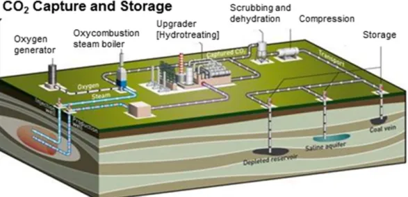
quantities, but this option is associated with potential leakage risks over the geological time scale (Haugan and Joos, 2004; Stone et al., 2009). Fig. 1 shows the schematic of processes involved in CO2
injection in subsurface geological storage reservoirs.
Fig. 1. Schematic of the processes involved in CO2 geological disposal (Courtesy of TOTAL).
- 2 -
1.2. The ways CO2 is stored in a geological reservoir
Injected supercritical free-phase CO2 moves upward and
accumulates beneath the overlying less-permeable caprock due to its lower density compared to that of the resident brine (Orr, (2009a, 2009b); Pool et al., 2013). Thus, the injection of free-phase CO2 is performed in subsurface reservoirs covered with overlying
less permeable caprock to stop its vertical movement and trap it in the reservoir below the caprock (García, 2003). The storage of injected CO2 in the reservoir can be classified into two main
categories; physical and chemical (IPCC, 2005). Structural trapping is a form of physical trapping where the free-phase CO2 is trapped under very-low-permeable caprock (IPCC, 2005). Hydrodynamic trapping is another form of physical trapping where injected CO2
stays as a free-phase in the pore spaces of deep aquifers (IPCC, 2005). Solubility, ionic and mineral trapping are considered forms of chemical trapping. Injected free-phase CO2 dissolves in the
reservoir fluid (solubility trapping), is converted into other carbon-bearing ionic species (ionic trapping) and is finally permanently consumed through mineral reactions (mineral trapping) (Zhang and Song, 2014; IPCC, 2005). Hydrodynamic trapping is the major form of CO2 storage over short periods of time, followed by
solubility trapping (tens to hundreds of years) and ionic trapping (hundreds to thousands of years), whereas mineral trapping spans over thousands to millions of years (Audigane et al., 2007; IPCC, 2005).
Dissolution between injected free-phase CO2 and the resident
formation fluid occur only at the CO2-brine interface (Orr, (2009a, 2009b)). The resulting brine, containing dissolved CO2, becomes
slightly denser than the original brine and starts moving downwards in the reservoir, resulting in enhanced dissolution and reduced leakage risk over the period of time (Weir et al., 1996; IPCC, 2005; Audigane et al., 2007). Dissolved CO2 decreases the
pH of the resident fluid, making it more reactive with the minerals in the subsurface reservoir (Xu et al., (2003, 2004); Audigane et al., 2007). Various aqueous-mineral geochemical reactions driven by dissolved CO2 cause minerals to either dissolve or precipitate,
causing variations in the porosity and permeability of the subsurface porous media (Xu et al., 2003). As a result of geochemical reactions, dissolved CO2 is converted into other carbon-bearing ions (ionic trapping), followed by its permanent consumption in various mineral reactions (mineral trapping) (IPCC, 2005; Audigane et al., 2007). Audigane et al. (2007) have reported a conversion of only 30% of injected CO2 in the dissolved phase after 1000 years, whereas it took 10,000 years for complete dissolution of injected CO2 in the reservoir. These
authors have also reported that only 5% of injected free-phase CO2 is consumed in mineral reactions over a period of 10,000 years. Thus, over a period of time and as a result of various types of trapping processes, including solubility, ionic, and mineral trapping, the quantities of injected free-phase CO2 continue to
- 3 -
1.3. Leakage risk of injected CO2 from a geological reservoir
The greatest risk of leakage is associated with free-phase CO2
being low in density and buoyant with respect to the resident fluids in the reservoir (Weir et al., 1996; Xu et al., 2003; IPCC, 2005; Xu et al., 2007; Audigane et al., 2007; Leonenko and Keith, 2008). Existing weaker zones, such as fractures or faults, that are not detected at the time of reservoir selection or new weaker zones developed by reservoir pressure increase as a result of the CO2
injection process, and subsurface tectonic activity may provide pathways for the leakage of buoyant free-phase CO2. Pressure
variations due to subsurface large-scale groundwater motions can also cause the leakage of free-phase CO2 from the storage reservoir
over longer time-scales. Thus, leakage of CO2 is one of the major
concerns related to the geological storage of CO2 (Haugan and
Joos, 2004; Stone et al., 2009).
Although the dissolution of CO2 in the resident brine makes it
slightly denser than the original brine, with a resulting downward convection in the reservoir, the risk of denser brine that contains dissolved CO2 also exists due to large-scale groundwater motion over longer periods of time. Large-scale groundwater motion may cause pressure variations in the reservoir, resulting in the leakage of CO2-charged brine along existing or pressured-induced
fractures and faults (IPCC, 2005). Leakage of dissolved CO2 may also take place as a result of the bulk displacement of brine carrying dissolved CO2 along the direction of movement of
groundwater (Gaus, 2010).
1.4. Physical and geochemical interactions of CO2 with porous media along the leakage pathway
Although the fluid flow takes place mainly in highly conducting zones, such as fractures and faults, the adjacent less-permeable rock matrix also plays an important role in the solute transport in the fractured porous media (Grisak and Pickens, 1980). Mass exchanges can take place between the principal transport pathway (fractures or conducting fault zones) and the relatively less permeable adjacent rock matrix. Various physical and geochemical processes between the solute mass species and the porous media can take place, thus inhibiting the transport of the solute mass species in the fractured rocks. Significant retardation in the species transport may result from various physical and geochemical interactions of transporting species with the porous media along the flow pathway (Neretnieks, 1980; Cvetkovic et al., 1999; Xu et al., 2001; Bodin et al., 2003).
In the event that leakage of CO2 from the storage reservoir takes
place, either as a free-phase or as a dissolved phase, the leaking CO2 may undergo various physical and geochemical processes along the transport pathway. The leaking CO2 may dissolve in the
fluid and undergo various geochemical reactions along the leakage pathway (Gaus et al., 2005; Gherardi et al., 2007; Ellis et al., 2011a; Nogues et al., 2013). Pore spaces of porous media may store dissolved CO2. Sorption processes may fix CO2 in the sorbed
- 4 -
geochemical reactions driven by the concentration of dissolved CO2 may also consume quantities of dissolved CO2 through its
conversion into ions, such as H2CO3, HCO3-, and CO3
2-(Kaufmann and Dreybrodt, 2007), followed by subsequent permanent removal in the form of precipitated carbonate minerals along the leakage pathway (Gaus et al., 2005). Mineral dissolution driven by dissolved CO2 may release ions such as Na+, Ca2+, Mg2+,
and Fe2+. These ions can form aqueous complexes, such as
NaHCO3aq, CaHCO3+, MgHCO
3+, and FeHCO3+, by utilizing the
bicarbonate ions available in the solution through the conversion of dissolved CO2. Kaufmann and Dreybrodt (2007), via
diffusive-reactive transport modelling, have reported the conversion of dissolved CO2 into H+ and HCO
3- species in a ternary CO2-H2
O-CaCO3 system. Gaus et al., 2005 have found consumption and
related retardation in the transport of dissolved CO2 in their
diffusive-reactive transport modelling performed for the lower part of the caprock. Thus, the interplay between the leakage pathway and the rock matrix is important for understanding the transport and fate of CO2 leaking from the reservoir.
Geochemical reactions between the leaking brine carrying dissolved CO2 and the minerals may cause geochemical alterations along the leakage pathway (Nogues et al., 2013). The leakage of low-pH brine has the potential to react with the host rock minerals, and it may cause variations in porosity and permeability of the medium along the flow pathway and influence the flow velocities. The variations in porosity and permeability along the flow pathway may either enhance the transport of leaking CO2 due
to the increase in hydraulic conductivity resulting from mineral dissolution or slow the transport processes as a consequence of the decrease in medium permeability linked to the mineral precipitation (Gaus, 2010). For example, a carbonate rock-forming mineral may undergo fast dissolution and widen the existing flow path (Gaus, 2010).
1.5. Injection of dissolved CO2 in the geological reservoir to reduce the leakage risk
Dissolution of CO2 in the resident brine of the reservoir increases the density of the resulting brine by approximately 1% (Bachu and Adams, 2003; Song et al., 2005; Duan et al., 2008; Zhang et al., 2011; Li et al., 2011). However, this increase in density resulting from CO2 dissolution depends on pressure, temperature and salinity conditions. The resulting denser brine tends to settle downwards in the storage reservoir. Thus, the risk of CO2 leakage
is generally reduced once it is dissolved in the resident brine. Migration and leakage of CO2 in the dissolved phase can only take place due to regional groundwater movement (IPCC, 2005). Deep subsurface groundwater moves very slowly, with velocities on the order of millimetres to centimetres per year (Bachu et al., 1994). Therefore, the leakage risk associated with injected supercritical free-phase CO2 in the subsurface reservoir can be reduced to a
greater extent by injecting CO2 in the dissolved phase (CO2aq)
- 5 -
Gislason and Oelkers, 2014). The increase in the density of brine containing CO2aq also makes it possible to inject CO2 in its
dissolved phase in subsurface reservoirs without the presence of overlying caprock (Gislason and Oelkers, 2014). Relatively shallow subsurface reservoirs can also be selected for the injection of CO2aq (Aradóttir et al., 2012). An immediate consumption of injected CO2aq can take place through solubility and ionic trapping
(Gislason and Oelkers, 2014). Additionally, relatively fast permanent removal of CO2 through mineral trapping can be expected for CO2aq injected in the reservoir (Aradóttir et al., 2012).
In the event of leakage of CO2aq, it is less likely to reach the land
surface due to its very slow movement, its significant retention caused by its mass being stored in aqueous and adsorbed states, and its conversion/consumption in various geochemical reactions along the travel pathways.
1.6. Rationale of the thesis
1.6.1.Reactive transport of leaking dissolved CO2 along the fractured pathway To date, no specific studies reported in the literature have analysed the retention and consumption of leaking CO2aq along a fractured
pathway based on physio-geochemical processes coupling mass exchanges between the conducting pathway and the surrounding less-permeable rock matrix.
Gherardi et al. (2007) have performed reactive transport modelling in the reservoir caprock for leaking free-phase CO2 and the
associated dissolved CO2 in the brine. These authors have found
porosity variations near the reservoir-caprock interface mainly due to reactions of mineral calcite. The experimental studies of Andreani et al. (2008) show an approximately 50% increase in porosity in close proximity to the fracture, mainly due to calcite dissolution caused by cyclic flows of the free-phase CO2 and CO2 -saturated brine. Gaus et al. (2005) have performed diffusive-reactive numerical modelling of dissolved CO2 diffusing from the
reservoir into the overlying caprock. These authors report a 2.8% decrease in porosity in the lower part of the caprock (within approximately 2 m of the reservoir-caprock interface) due to the precipitation of the minerals calcite and kaolinite associated with the dissolution of the mineral anorthite after a period of 3000 years. Nogues et al. (2013), in their reactive transport modelling, have analysed the evolution of porosity and permeability at the pore-scale level driven by inflowing CO2-saturated water. These
authors have suggested that the geochemical modelling can be simplified by not including minerals, such as kaolinite, anorthite, and albite, where the carbonate minerals are present in abundance. Ellis et al. (2011a), in their experimental study performed for a period of seven days, investigated the geochemical evolution of fracture in carbonate rock due to geochemical interactions with flowing CO2-acidified brine. Ellis et al. (2011a, 2011b) have found
an increase in fracture aperture mainly due to calcite dissolution. Only a few experimental and simplified numerical modelling studies have been published thus far focusing on the geochemical
- 6 -
interactions of CO2–acidified brine (Gaus, 2010). Gaus (2010) has thus identified the need to perform numerical modelling for the leakage of brine carrying dissolved CO2 from the storage reservoir
towards shallow depths to understand the related environmental impacts. Thus, to bridge the existing knowledge gap and investigate the fate of leaking CO2aq, this study focuses on the
numerical simulation of the reactive transport of brine carrying CO2aq along a fractured pathway.
1.6.2.Injection of dissolved CO2 in a geological reservoir
The injection of CO2 in its dissolved phase has been proposed to
increase the security of its geological sequestration (Aradóttir et al., 2012; Pool et al., 2013; Gislason and Oelkers, 2014). However, thus far, few numerical studies related to reactive transport modelling of injected dissolved-phase CO2 and quantification of its
transformation through geochemical reactions have been published (e.g., Aradóttir et al., 2012). Pool et al. (2013), in their numerical modelling, injected CO2aq in the aquifer without considering its geochemical interactions with minerals. Thus, to augment the understanding and complement the existing studies on the subject, this work also focuses on the injection of CO2aq
and quantifies its transformation through geochemical reactions in the carbonate reservoir.
2. R
ESEARCH OBJECTIVESThe aims of this PhD thesis are twofold. First, the study focuses on the reactive transport modelling of CO2aq leaking from
geological storage reservoirs. The overall aim is quantification of the mass stored in aqueous and adsorbed states and consumed in reactions of leaking CO2aq along a fractured pathway (Papers I-III). The following are the specific objectives of the individual Papers I-III:
• Investigate the role of physical and geochemical transport processes on the transport of leaking CO2aq along the
fractured pathway using a simplified model that considers only diffusion in the rock matrix (Paper I).
• Investigate how advection in the rock matrix affects different physical and geochemical transport processes influencing the fate of leaking CO2aq along the fractured
pathway (Paper II).
• Investigate the role of additional geochemical reactions, temperature and heat transport on the leaking CO2aq along
the fractured pathway (Paper III).
The study also investigates a relatively safer approach of CO2
geological disposal where it is injected in its dissolved phase in shallow carbonate reservoir. Reactive transport modelling is performed considering physical and geochemical interactions of the injected CO2aq in the carbonate reservoir. The objectives of
Paper IV are:
• To quantify the mass stored in aqueous and adsorbed states and consumed in reactions of CO2aq injected in the
- 7 -
carbonate reservoir. The roles of dispersion, temperature and pH-dependent mineral reaction kinetics are also investigated.
3. M
ETHODOLOGY3.1. Model approach and numerical solution
In this study, geochemical code was developed and implemented in COMSOL, which is a finite element-based multiphysics simulator, to perform the batch and reactive transport modelling. Flow and transport were coupled with geochemistry while taking into account the spatial and temporal variations in medium porosity and permeability resulting from mineral dissolution and precipitation. The developed geochemical code is capable of solving the geochemical reactions system (equilibrium plus mineral kinetics), updating the minerals’ reactive surface area and tracking the variations in porosity and permeability. MATLAB was externally coupled with COMSOL to compute the density and viscosity of the brine fluid as well as fugacity and the activity coefficients of dissolved CO2. MATLAB is a language and
interactive environment used for technical computing. These variables were solved as a function of pressure, temperature and the concentration of aqueous species. The variables shared between COMSOL and MATLAB are updated every iteration. Fig. 2 presents a schematic of the coupling between COMSOL with MATLAB.
The reactive transport problem of mobile species was formulated in terms of chemical component species (u) that are the linear combination of aqueous species concentrations involved in geochemical reactions. The mass of rock-forming minerals (immobile) participating in the kinetic reactions was conserved through the solution of an ordinary differential equation (ODE). Two numerical approaches are available in COMSOL to solve the nonlinear multiphysics problems: fully coupled and segregated. The Newton-Raphson iteration scheme is used in both of these approaches. In the fully coupled approach, various involved physics are coupled and solved at the same time. However, a fully coupled approach proves to be both memory- and time-intensive.
Fig. 2. Schematic of the coupling between COMSOL and MATLAB.
- 8 -
The segregated solution approach solves various involved physics problems sequentially by solving for various variables in sequence. The iteration process is continued until convergence is achieved. Iteration in the segregated approach takes less time than the iteration of the fully coupled approach. The segregated solver approach generally solves faster and proves to be more memory efficient than the fully coupled approach. Thus, in this study, a segregated technique that splits the solution process into sub-steps was used to solve the coupled reactive transport problem. A backward differentiation formula (BDF)-based time-dependent nonlinear solver was used with a Jacobian matrix that was updated every iteration. A damped version of Newton’s method with a damping factor of 1 was used in all the involved sub-steps. The flow problems (pressure and velocity) were solved together in step 1. The transport of component species and the associated speciation were solved together in step 2. The temperature in the case of heat transport was solved in step 3, and finally, the mass conservation of kinetically controlled minerals was solved in step 4.
Various physical and geochemical interactions of leaking dissolved CO2 with the porous media along the leakage pathway are included in the study. The geochemical reaction systems that may vary between the papers are considered in the reactive transport modelling. All the geochemical reactions, either equilibrium or mineral kinetics, are modelled as a function of temperature.
Storage of dissolved CO2 in the pore spaces, its sorption on the
mineral surfaces, and its conversion and consumption in aqueous and mineral reactions were analysed in the reactive transport modelling. Retention and related retardation of leaking dissolved CO2 arising from considered physical and geochemical processes
are investigated in the transport analysis. 3.2. Geochemical reaction system
Table 1 presents the overall geochemical system used in this study, which describes the water-rock interactions. First, eight reactions ((R0) to (R7)) are assumed to be fast and are thus modelled through the equilibrium assumption, whereas the last three reactions ((R8) to (R10)) are relatively slow mineral (calcite, dolomite and siderite) reactions and thus treated as kinetically controlled. The equilibrium between free-phase CO2 and dissolved phase CO2 was modelled by reaction (R0). The solubility model
developed by Duan and Sun (2003), later improved by Duan et al. (2006), was used to model the solubility of CO2 in the NaCl brine
solution. The used model calculates the solubility of CO2 in aqueous solutions containing Na+, Cl-, K+, Ca2+, Mg2+, and SO
42-.
This model covers wide ranges of pressure (from 0 to 2000 bar), temperature (from 273 to 533 K) and ionic strength (from 0 to 4.5 molal solutions). In their experimental study, Dilmore et al. (2008) have reported the reliability of the model of Duan and Sun (2003) to determine the solubility of CO2 in the saline brine.
Reaction (R0) was only included in the batch geochemical modelling and was not involved in the subsequent reactive
- 9 -
transport modelling because the latter was performed for single-phase brine carrying dissolved CO2.
3.3. Batch geochemical modelling
Batch geochemical modelling (BGM) simulates the equilibrium and mineral kinetic reactions without involving transport (Parkhurst and Appelo, 2013). In BGM, geochemical interactions between CO2, pore water and rock minerals are performed until
equilibrium. Batch reaction modelling was subdivided into (i) background BGM and (ii) CO2 dissolution modelling. Background
BGM was performed in the reservoir containing previously injected CO2 as well as in the fractured caprock that was
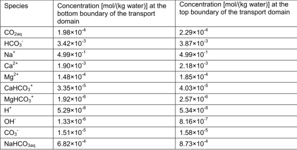
considered a leakage pathway (transport domain) lying above the reservoir. Background BGM provides the information of pressure (P), temperature (T) and geochemical conditions initially prevalent in the transport domain and was used as the initial conditions for the subsequent reactive transport modelling. BGM also provides the composition of the resident brine solution initially present in the reservoir before the placement of CO2.
3.3.1.Background batch geochemical modelling
The initial pressure and temperature distribution in the transport domain was defined based on a hydrostatic pressure gradient of 1×10⁴ Pa/m and a geothermal gradient of 0.03°C/m below the
land surface (Pruess, 2008). The initial concentrations of dissolved species and related component species were found from the background BGM performed at a CO2 partial pressure (PCO2) of 1×10³ Pa (Xu et al., 2005), adopting a 0.5 molar (M) solution of
sodium chloride (NaCl) while including the fluid-mineral geochemical interactions.
The value of 0.5 M was adopted for the NaCl solution arbitrarily to represent the saline brine. The species chloride (Cl-) was
assumed to be conservative for its lack of participation in reactions Table 1. Equilibrium and mineral kinetic reactions considered in the study.
No. Reactions (R0)* CO ↔ CO (R1)** H O + CO ↔ H + HCO (R2)** H O ↔ H + OH (R3)** HCO ↔ H + CO (R4)** Na + HCO ↔ NaHCO (R5)** CaHCO ↔ Ca + HCO (R6)** MgHCO ↔ Mg + HCO (R7)** FeHCO ↔ Fe + HCO (R8)** CaCO + H ↔ Ca + HCO (R9)** (CaMg)CO + 2H ↔ Ca + Mg + 2HCO (R10)** FeCO + H ↔ Fe + HCO
*Equilibrium reaction constant is based on Duan and Sun (2003) as modified by Duan et al. (2006).
**Equilibrium reaction constants are opted from “LLNL thermo database” (Delany and Lundeen, 1990) which is also used by The Geochemist’s Workbench® as its default thermodynamic data.
- 10 -
considered in this study (Table 1). The resident brine composition in the fractured clay-rich caprock (transport domain) obtained from the background BGM was in equilibrium with respect to the considered carbonate minerals, and thus, there was almost no reactivity between the fluid and the minerals. Thus, any reactivity in the subsequent reactive transport modelling can be attributed solely to the CO2-saturated brine leaking from the reservoir.
3.3.2.CO2 dissolution modelling
The composition of CO2-saturated brine supposed to be leaking from the reservoir and that was required as a boundary condition for the reactive transport modelling was obtained by performing CO2 dissolution modelling. In CO2 dissolution modelling, the
pressure of CO2 was increased from a background pressure of 1×10³ Pa to a value that represents the pressure conditions of the
top boundary of the reservoir. Geochemical interactions between the considered carbonate minerals in the reservoir and the brine containing dissolved CO2 were modelled until equilibrium conditions were reached with respect to the minerals.
3.4. Reactive transport modelling
3.4.1.Leakage of single-phase brine saturated with dissolved CO2
For the fracture-matrix system, the solute transport in the fracture is governed by three transport processes, namely advection, dispersion and diffusion whereof diffusion is often acknowledged as the only transport process in the matrix (Novak, (1993, 1996); Steefel and Lichtner, (1998a, 1998b)). Hence, the mass exchange between the conducting principal pathway (fracture or fault zone) and the neighbouring less-permeable rock matrix takes place through matrix diffusion alone. In the first step, based on this concept, reactive transport modelling of the leaking dissolved CO2
was performed by considering the diffusion alone as the the only transport process in the rock matrix (Paper I). However, in this thesis, the analysis was extended by including advection and dispersion in addition to diffusion as the transport processes in the rock matrix (Papers II and III). Reactive transport of leaking dissolved CO2 was performed for a period of 500 years. For the
considered time-scale, only the carbonate minerals calcite and dolomite, due to their fast kinetics, were considered for geochemical interactions with the brine carrying dissolved CO2,
whereas other minerals, present in the clay-rich caprock were considered non-reactive.
Conceptual transport model
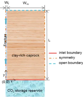
A conceptual model used for the reactive transport of leaking CO2-saturated brine, studied in Papers I, II and III, is presented in
Fig. 3. A geological porous formation, with its upper boundary at a depth of 1040 m below the land surface, was assumed as a storage reservoir containing previously injected supercritical CO2. The
reservoir was assumed to be covered with overlying clay-rich low-permeable caprock containing a conducting fracture. The transport domain consists of a principal conducting pathway (fracture) on the left and the less-permeable rock matrix on the right. Symmetry
- 11 -
was assumed along the left boundary in the y-direction (centre of the conducting pathway) and right side boundary of the rock matrix in the y-direction. Thus, no no-flow conditions were applied at the left side boundary (centre of the fracture) and the right side boundary of the rock matrix. CO2-saturated brine leaking from the reservoir enters the transport domain through bottom inlet boundaries (y=0). After flowing through the fractured pathway, the fluid can leave the domain through the top boundaries (y=L). The mineralogical composition of clay-rich caprock was taken from Gherardi et al. (2007), with an initial porosity equal to 0.12 (Table 2).
3.4.2.Injection of dissolved CO2 in the reservoir
In Paper IV, a porous carbonate reservoir (depth (D) = 250 m and width (W) = 500 m) was considered for the injection of dissolved CO2 (Fig. 4). A 2D axisymmetric model was used in this reactive
transport modelling. The upper boundary of the reservoir ( = 0) was considered to be 400 m below the land surface. CO2-saturated
Table 2. Mineral composition of clay-rich caprock (Gherardi et al., 2007). Minerals Volume fraction in solid rock Volume fraction in porous rock (12% porosity)
Calcite 0.29 0.255 Dolomite 0.04 0.035 Quartz 0.20 0.176 Illite 0.02 0.018 K-feldspar 0 0 Chlorite 0.06 0.053 Albite 0 0 Kaolinite 0.05 0.044 Na-smectite 0.15 0.132 Muscovite 0.19 0.1672
Fig. 3. Schematic of clay-rich caprock with a conducting pathway (fracture) overlying the CO2 storage reservoir (not to scale).
- 12 -
brine was injected through a 0.1 m wide inlet section at the left side (0 0.1) of the top boundary of the reservoir. A symmetry boundary with no-flow conditions exists across the left vertical boundary. Fluid can exit through the bottom and right vertical boundaries, whereas the top boundary was defined as a no-flow boundary. The reactive transport for the injection of dissolved CO2 was performed for a period of 10 years.
3.4.3.Reactive transport and mass conservation of mobile species
The reactive transport system of mobile aqueous species was defined by the following equation written in terms of the species concentrations vector ( ) (COMSOL):
+ − − ∙ [( + ) ] + ∙ ( ) = (1)
In this study, the reactive transport problem was formulated in terms of component species. Thus, in Eq. (1), a vector of aqueous species concentrations ( ) was replaced by a vector of concentrations of component species ( ):
+ 1 − − ∇ ∙ [( + )∇ ] + ∇ ∙ ( ) = (2)
where
= 1 + (3)
where ∇ = (∂/∂x,∂/∂y) is the Nabla operator; u (x,y,t) is the vector of concentrations [mol/(kg water)] of the component species; Rf (x,y,t) is a diagonal matrix of retardation factors accounting for sorption of mobile component species with immobile phases; Kd (x,y,t) is a diagonal matrix where the diagonal elements include the sorption partition coefficients for involved component species [m3/kg]; (x,y,t) is the spatially and temporally varying porosity;
(x,y,t) is the particle density [kg/m3] of the rock formation;
(x,y,t) is the bulk density [kg/(m3 bulk volume)] of the porous
Fig. 3. Schematic of the carbonate reservoir considered for the storage of dissolved CO2 (not to scale).
- 13 -
media that changes with the porosity of the medium; DD is the dispersion tensor [m2/s]; D
e is the effective diffusion (diagonal) tensor [m2/s] defined as a function of porosity of the medium;
v(x,y,t) is Darcy’s velocity vector [m/s] updated in space and time; and rkin(x,y,t) is the source/sink term defining the consumption or production of component species [mol/(s-kg water)]. In transport equations (2-3), u and rkin are vectors of size equal to the number of component species, whereas Rf and Kd are matrices with rows and columns equal to the number of component species. The transport equations (2-3) are nonlinear partial differential equations in which the variables ( , , ), the matrices (Rf and Kd) and the reaction term (rkin) are all nonlinear functions of the local concentrations of component species. The detailed methodology of calculating the medium porosity ( ), the particle density of rock ( ) and the bulk density ( ) of the medium is presented in Appendix A.
The transport equations (2-3) were written in terms of component species (u) that are defined as a linear combination of aqueous chemical species involved in the considered geochemical reaction system (Yeh and Tripathi, 1991; Steefel and Lasaga, 1994; Xu and Pruess, 2001). The mass conservation of aqueous species in the form of component species and the related source/sink term (rkin (x,y,t)) involved in Eq. (2) were formulated following the methodology of Saaltink et al. (1998). A detailed formulation of aqueous species in terms of component species, derivation of the reaction term (rkin) and speciation was presented in the various papers for the considered reaction systems. The equilibrium reactions are defined through the law of mass action and result in algebraic equations. These algebraic equations were solved to compute the involved aqueous species as a function of transport component species (called speciation). Computation of the involved aqueous species is required because all the geochemical reactions are defined in terms of aqueous species. The transport system defined in terms of component species requires defining (i) the initial values of all aqueous species involved in the geochemical reactions and (ii) the initial and boundary values expressed in terms of the involved component species. The previously stored numerical solution from the BGM was used as the initial conditions in the subsequent reactive transport modelling. The transport problem can thus be solved by only specifying the boundary conditions.
3.4.4.Mass conservation of minerals
The minerals (considered as immobile species) undergoing kinetic reactions were mass conserved by means of the following ordinary differential equation (ODE):
, = − (4)
where , is a vector representing the set of concentrations
[mol/(m3 bulk volume)] of individual mineral (
- 14 -
density of brine/fluid, and is the medium porosity updated in time and space (Eq. 15). The initial values of mineral concentrations ( , ) were calculated from the initial volume
fractions of the respective minerals in the porous media given in Table 2. The reaction term is a vector representing the consumption or production [mol/(s-kg water)] of the individual mineral ( ) that was defined in relation to its kinetically controlled dissolution or precipitation (Eq. 10).
3.4.5.Velocity field for the transport system
The velocity field in the transport equation (Eq. 2) was defined by the Brinkman equations. The Brinkman equations are a combination of the continuity equation and the momentum balance equation to define flow in the porous media:
( )
+ ∇ ∙ ( ) = (5)
+ ( ∙ ∇) = −∇ + ∇ ∙ (∇ + (∇ ) ) −2
3(∇ ∙ )
− + + (6)
where is the density [kg/m3] and is the dynamic viscosity
[kg/(s-m)] of NaCl brine; is the pressure [Pa]; is the permeability of the porous medium [m2]; and is the mass source
or sink, taken as zero in this study. The effect of gravity was included via the force term ( = − ), where g is the gravitational acceleration vector (9.81 m/s2). The Brinkman
equations extend Darcy’s law by introducing a term that accounts for the viscous effects in the momentum equation and defines both the pressure gradient and the flow velocity as independent vectors. Consistent with the Darcy law, the Brinkman equation represents the proportionality between the pressure gradient (first term on the right-hand side of Eq. (6)) and the viscous friction loss (represented by the third term on the right-hand side of Eq. (6)) but also include the inertia terms of the momentum equation. Popov et al. (2009) have reported the suitability of the Stokes-Brinkman equation for modelling the flow field in the porous media coupled to free flow regions, such as fractures, vugs, and caves. Gulbransen et al. (2010) have advocated for the Stokes-Brinkman equation compared to the Darcy-Stokes equation for modelling flow in the porous media and the free-flow regions where inertia effects are significant. Further, Brinkman equations are attractive numerically because they define the flow field in two regions (free flow and porous media) using a single system of equations, where the individual domain is represented by implicit parameters instead of the two-domain approach (Gulbranson et al., 2010). Several studies reports the use of Brinkman equations in COMSOL for modelling the flow in porous media (Sajjadi et al., 2014; Chabonan et al., 2015; Golfier et al., 2015; Basirat et al., 2015). The fluid density and viscosity were modelled as a function
- 15 -
of the temperature, pressure and concentration of dissolved species (CO2aq, Na+, and Cl-). The code for formulation of fluid
density and viscosity was developed based on the available published literature and was coupled with the transport problem. The detailed formulations for fluid density and viscosity are presented in Paper IV.
3.4.6.Heat transport
The following equation was used to model the heat transport by the migrating brine and its exchange with the porous media along the travel pathway (Bear and Bachmat, 1990; COMSOL):
+ , ∙ ∇ = ∇ ∙ ∇ + ∇ ∙ ( ∇ ) (7)
where
= (1 − ) , + , (8)
and
= (1 − ) + (9)
where is the temperature [K]; and represent the equivalent volumetric heat capacity [J/(m3-K)] and thermal
conductivity [W/(m-K)], respectively, of the solid-fluid system at constant pressure; and represent the density [kg/m3] of
porous media and fluid respectively; , and , are the heat
capacity [J/(kg-K)] of porous media and fluid respectively; and are the thermal conductivity [W/(m-K)] of porous media and fluid respectively; = , is the dispersive thermal conductivity; and represents the Darcy’s velocity defined by equations (5-6). Here the thermal dispersion ( ) was defined as a function of thermal dispersivity which was taken equal to 1 m. The specific heat capacity of porous media was taken as 920 J/(kg-K), whereas its thermal conductivity was taken as 2.51 W/(m-K) (Pruess, 2005). The heat capacity ( , ) and thermal conductivity
( ) of water carrying dissolved CO2 were calculated on the mass
averaged basis of water and dissolved CO2, whereas the effects of
other dissolved species were ignored (Papers III and IV). 3.4.7.Mineral kinetics
The reaction rate in Eq. (4), which represents the consumption or production [mol/(s-kg water)] of the mineral as a result of its kinetic reaction, is defined as a function of the involved aqueous species and mineral reactive surface area (Lasaga et al., 1994):
= 1 − (10)
where is the temperature-dependent kinetic rate constant of the mineral [mol/(s-m2)], and is the reactive surface area of the
mineral [m2/(kg water)] updated in time and space as a function of
- 16 -
respective mineral. The ratio ( ⁄ ) defines the saturation state of the mineral. The mineral dissolves in the solution if the saturation state of the solution with respect to the mineral is lower than unity, and it can precipitate if the saturation state of the solution becomes greater than unity. The term is the equilibrium constant of the mineral defined as a function of temperature, whereas the term is called the ion activity product of the mineral, which is a function of the local concentrations of the involved aqueous species (e.g., for calcite H+, Ca2+, and HCO
3
-). The temperature dependent kinetic rate constant of the mineral ( ) is defined by the following Arrhenius equation (Lasaga, 1984):
= − 1− 1
298.15 (11)
where is the reaction constant [mol/(s-m2)] of the mineral at
25°C, is the activation energy of the mineral [J/mol], is the gas constant equal to 8.314 J/(mol-K), and is the temperature [K]. The parameters used in Eq. (11) for various minerals considered in this study are presented in Table 3.
In Paper IV, to investigate the solution pH dependence of mineral kinetic reactions, the mineral kinetic rate constant was also defined by using the following relation (Palandri and Kharaka, 2004):
= − 1− 1 298.15 + − 1 − 1 298.15 + − 1− 1 298.15 (12)
The above relation considers three mechanisms (acid, neutral and base) for computing the mineral kinetic rate constant. In Eq. (12), the superscripts H, nu, and OH represent the acid, neutral and base mechanisms, respectively; represents the activity of H+;
and the superscripts and are the reaction order with respect to the activity of H+. The parameters for Eq. (12) are
presented in Table 4. All three mechanisms (acid, neutral and base) are involved in the rate constant for the minerals calcite and dolomite (Palandri and Kharaka, 2004), whereas the rate constant of siderite is defined by the acid and neutral mechanisms (Xu et al., 2007).
3.4.8.Computation of the activity coefficients of aqueous species
The chemical species appear in the geochemical reactions as their activity and not as their concentration. The activity of aqueous chemical species ( ) is the product of the activity coefficient ( ) Table 3. Parameters for the various minerals involved in Eq. (11). Mineral k25 [mol/(s-m2] Ea [KJ/mol] Reference
calcite 1.60×10⁻⁹ 41.87 Svensson and Dreybrodt (1992) dolomite 0.6×10⁻⁹ 41.87 assumed based on calcite siderite 0.6×10⁻⁹ 41.87 assumed based on calcite
- 17 -
and the species concentration ( ) related through the following relation:
= (13)
where is the standard concentration [1 mol/(kg water)]. The species activity coefficient is defined as a function of the species concentration in the solution. The activity coefficient of dissolved CO2 was based on the model presented by Duan and Sun (2003).
The activity coefficients of electrically charged species were obtained from the extended Bebye-Hückel function (B-dot model), whereas the activity coefficients of electrically neutral species were calculated using the relationship presented by Bethke (2008) (Paper I).
3.4.9.Mineral reactive surface area
Mineral dissolution or precipitation through mineral kinetic reactions not only cause variations in the porosity and permeability of the medium but also result in variations in the reactive surface area of the minerals involved in reactions. Variations in the mass of minerals [mol/(m3 bulk volume)] result from their geochemical
interactions with the fluid, expressed by Eq. (4), that in turn change the reactive surface area [m2/(kg water)] of the minerals.
The temporally and spatially varying reactive surface area of the mineral ( ) was computed using the following relation:
= 0.1 ( ) , (14)
where and represent the physical surface area and volume of the mineral grain, respectively, assuming the grain is spherical with a radius of 1.65×10⁻⁵ m; is the molar volume of the mineral;
is the density of brine fluid; and , is the mineral concentration updated in time and space through Eq. (4). Eq. (14) also accounts for the effects of fluid density ( ) that may vary in time and space. A multiplication factor of 0.1 represents the mineral’s reactive surface area as a fraction of its corresponding geometrical surface area (Johnson et al., 2004). The detailed methodology of computing the initial and varying reactive surface area ( ) of minerals is presented in Appendix A.
3.4.10. Medium porosity
Minerals can either dissolve or precipitate in the computational domain over a period of time, causing changes in the Table 4. Parameters for the various minerals involved in Eq. (12).
Mineral Acid mechanism Neutral mechanism Base mechanism [mol/(s-m2)] [KJ/mol] [mol/(s-m2)] [KJ/mol]
[mol/(s-m2)] [KJ/mol] calcite* 0.50 1 14.3 1.55×10⁻⁶ 23.5 3.31×10⁻⁴ 1 35.4 dolomite* 1.74×10⁻⁴ 0.5 56.7 2.51×10⁻⁹ 95.3 4.27×10⁻⁶ 0.5 45.7 siderite** 6.46×10⁻⁴ 0.5 36.1 1.26×10⁻⁹ 62.76 0 -- --
- 18 -
concentrations of minerals through Eq. (4). This causes changes in the mineral volume fraction and thus the porosity of the porous media. These space- and time-dependent variations in the porosity of the porous media were modelled in relation to the updated volume fraction of minerals of the porous media using the following relation:
= 1 − , (15)
where , = ∑ , is the sum of the volume fractions of
all the minerals composing the porous rock; and , = , / , [-] is the volume fraction of the mineral, expressed as
the ratio of the mineral volume to the total volume of the porous medium. The detailed methodology of calculating the medium porosity ( ) from the updated volume fraction of minerals forming the porous rock medium is also presented in Appendix A. The medium porosity was not allowed to reach unity by setting a minimum threshold concentration value for all the involved minerals of 1×10⁻⁷ [mol/(m3 bulk volume)] in Eq. (4). Porosity of
the medium was also maintained at a minimum value of 1×10⁻³ by
stopping precipitation of minerals whenever the porosity falls to this minimum value in the domain.
3.4.11. Medium permeability
The initial permeability ( ) of the porous medium was found from the Kozeny-Carman relation as a function of the initial porosity ( ) and the mineral composition of the porous media (Bear and Cheng, 2010):
=
(1 − ) , (16)
where is a coefficient equal to 0.2 and , is the initial
specific surface area of the solid rock per unit volume of the solid rock [m2/m3], which depends on the initial mineral composition of
the porous media (Bear & Cheng, 2010). The expressions for calculating , are also presented in Appendix A. The
medium permeability was updated in time and space as a function of the medium porosity using the following Kozeny-Carman relation (Lai et al., 2014):
= (1 − )
(1 − ) (17)
3.4.12. Sorption of mobile species on mineral surfaces
Aqueous species may undergo a sorption process on the surfaces of the minerals in the porous media. The sorption process may fix the quantities of aqueous species in the sorbed state and may cause the transport retardation of species. The effect of sorption appears in the transport equations (2-3) through the retardation factor (Rf). A linear Kd model was used to study the sorption of aqueous
- 19 -
reaction (Freeze and Cherry, 1979; Bodin et al., 2003; Bear and Cheng, 2010):
, = , (18)
where , is the i-th component of the vector of concentrations of
aqueous species sorbed on the surface of a solid phase (immobile minerals) that is expressed as the species concentration per unit mass of a solid [mol/kg], is the i-th component of the vector of concentrations of species in the fluid phase [mol/m3],
, is the
i-th diagonal component of i-the partition matrix , and thus has the units of m3/kg. However, in this study, the sorption
process was modelled using a constant value of the partition coefficient Kd for all species.
Various minerals have shown the ability to adsorb CO2 on their surfaces (Santschi and Rossi, 2006; Fujii et al., 2010; Tabrizy et al., 2013; Heller and Zoback, 2014). Calcite presents a partition coefficient of 6.6×10⁻² m3/kg for CO
2 (Santschi and Rossi, 2006).
In their experimental study, Fujii et al. (2010) have observed the adsorption of CO2 on various rocks and minerals at temperature
and pressure conditions relevant to CO2 geological storage. In the
experimental study of Heller and Zoback (2014), the clay sample “Eagle Ford” consisting of mainly calcite (80%) has shown a partition coefficient of 7.39×10⁻⁴ m3/kg for CO
2 at a pressure of
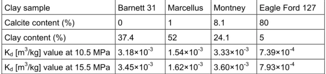
10.5 MPa (relevant pressure conditions in the CO2aq leakage
modelling in this study). The deduced values of the partition coefficient for various clay samples from the study of Heller and Zoback (2014) are presented in Table 5.
In this study, three different values (7.50x10⁻⁴, 2.50x10⁻⁴, and
8.33x10⁻⁵ m3/kg) of the partition coefficient were used that are
lower than the values reported by Santschi and Rossi (2006) and by Heller and Zoback (2014). In addition, the same value of the
Table 6. Parameters for equations (19-20) computed at three different pressure and temperature conditions.
Pressure and
Temperature Viscosity of water (μ ) [kg(m-s)] Viscosity of brine (μ ) [kg/(m-s)] Diffusion coefficient of CO2 in water (D ) [m2/s] Diffusion coefficient of CO2 in brine (D ) [m2/s] 41×105 Pa and 27°C 8.51×10⁻⁴ 8.90×10⁻⁴ 2.10×10⁻⁹ 2.02×10⁻⁹ 105×105 Pa and 45°C 5.96×10⁻⁴ 6.27×10⁻⁴ 3.19×10⁻⁹ 3.05×10⁻⁹ 151×105 Pa and 60°C 4.69×10⁻⁴ 4.94×10⁻⁴ 4.25×10⁻⁹ 4.05×10⁻⁹
Table 5. Sorption partition coefficient (Kd) for CO2 for various clay samples (Heller and Zoback, 2014).
Clay sample Barnett 31 Marcellus Montney Eagle Ford 127
Calcite content (%) 0 1 8.1 80
Clay content (%) 37.4 52 24.1 5
Kd [m3/kg] value at 10.5 MPa 3.18×10⁻³ 1.54×10⁻³ 3.33×10⁻³ 7.39×10⁻⁴ Kd [m3/kg] value at 15.5 MPa 3.45×10⁻³ 1.62×10⁻³ 3.60×10⁻³ 7.93×10⁻⁴
- 20 -
partition coefficient was used for all the aqueous species due to the large uncertainty in the sorption properties and the involved complex geochemical interactions.
3.4.13. Diffusion of species in porous media
The species diffusion in the porous media was defined as an effective diffusion ( ) that is related to the medium porosity ( = ), where is the identity tensor. The diffusion coefficient for dissolved CO2 in brine fluid ( ) was computed
from its diffusion coefficient in water ( ) as follows (Al-Rawajfeh, 2004; Hassanzadeh et al., 2008):
= 10[ . ] (19)
where and represent the viscosities of water and brine (H2O+NaCl+CO2), respectively. The viscosity of pure water and
brine fluid was computed from the model presented by Mao and Duan (2009) (Paper I). The diffusion coefficient of dissolved CO2
in water was calculated from the relation (Al-Rawajfeh, 2004):
= 10( . . . × ) (20)
The viscosity of water and brine and the diffusion coefficient of CO2 in water and brine were computed from equations (19-20) at
various pressure and temperature conditions as presented in Table 6. The computed value of the diffusion coefficient ( ) for dissolved CO2 was taken as the diffusion coefficient for all the
mobile species (Gherardi et al., 2007).
3.4.14. Methodology for calculating the mass conversion of CO2 in geochemical reactions
The mass consumption of CO2aq in geochemical reactions in each
reactive transport scenario was computed by comparing CO2aq
mass balances with the corresponding mass transport scenario without involving those reactions presented in Table 1. Thus, in this study, in addition to the reactive transport scenarios, an equal number of mass transport scenarios were also performed for computation of the mass consumption of CO2aq in each reactive transport scenario. In addition to presenting the mass consumption in terms of cumulative quantities ( ), it was also
presented as a percentage (% = ) of cumulative
quantities that entered the domain ( ) from the reservoir over the period of time.
3.5. Detailed description of various transport processes analysed in the various papers
Table 7 provides the summary of various transport processes studied in Papers I through III. Sections 3.5.1 – 3.5.4 describe the details of various transport processes analysed in the individual papers.
- 21 - 3.5.1.Paper I
In this paper, a bedrock fracture was considered as the principal conducting pathway with porosity of 100% and without any infill material. The adjacent less-permeable rock matrix was assumed as a stagnant zone. Advection, dispersion and diffusion were considered as the transport processes in the conducting fracture, whereas diffusion was the only transport process considered in the neighbouring rock matrix for mass exchange between the fracture and the matrix. The considered transport domain was 20 m long, consisting of a 1 mm wide fracture on the left and a 10 m wide rock matrix on the right (Fig. 3). In the base-case scenarios (Table 8), a constant vertical fluid velocity in the fracture was taken as 3.171×10⁻⁷ m/s (nearly 10 m/year). The longitudinal dispersion
coefficient (DL) in the fracture was defined using Taylor-Aris dispersion:
= = + 2
105 (21)
where and represent the vertical mean velocity in the fracture and the half-width of the fracture spacing, respectively. The mean velocity is generally expressed as v/θ, where v is the Darcy velocity, but the porosity was 100% in the considered fracture. Both diffusion and dispersion processes are embedded in Eq. (21) for the case of fracture.
The geochemical system considered in this paper includes four equilibrium reactions and one kinetic reaction of mineral calcite ((R1)-(R4) and (R8) presented in Table 1). For the considered reaction system, a total of four (4) component species result from eight (8) aqueous species that were involved in the geochemical reactions. Thus, for the considered geochemical system in Paper I, the transport equations (2–3) involve four component species. Aqueous-phase equilibrium reactions were considered in both the fracture and the rock matrix, whereas the calcite kinetic reaction was only considered in the rock matrix.
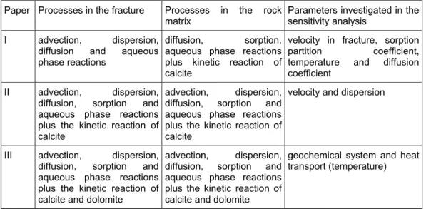
Table 7. Summary of transport processes modelled in Papers I through III. Paper Processes in the fracture Processes in the rock
matrix Parameters investigated in the sensitivity analysis I advection, dispersion,
diffusion and aqueous phase reactions
diffusion, sorption, aqueous phase reactions plus kinetic reaction of calcite
velocity in fracture, sorption
partition coefficient, temperature and diffusion
coefficient II advection, dispersion,
diffusion, sorption and aqueous phase reactions plus the kinetic reaction of calcite
advection, dispersion, diffusion, sorption and aqueous phase reactions plus the kinetic reaction of calcite
velocity and dispersion
III advection, dispersion, diffusion, sorption and aqueous phase reactions plus the kinetic reaction of calcite and dolomite
advection, dispersion, diffusion, sorption and aqueous phase reactions plus the kinetic reaction of calcite and dolomite
geochemical system and heat transport (temperature)
- 22 -
To evaluate the significance of the physical and geochemical transport processes on the transport of leaking dissolved CO2,
various scenarios were modelled for a period of 500 years (Table 8). Mass transport without involving any of the geochemical reactions (those presented in Table 1) was analysed in the different mass transport scenarios 1, 2 and 3, whereas reactive transport was modelled in scenarios 4 and 5. Scenario 1 considers the fluid flow only in the fracture without any interaction between the fracture and the matrix. Sorption was included in scenarios 4 and 5 by using a partition coefficient of 2.50x10⁻⁴ m3/kg. We considered
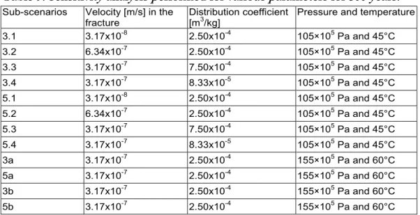
scenarios 1 to 5 as the base-case scenarios. Sensitivity analysis was also performed to understand the effects of various parameters (velocity in the fracture, sorption partition coefficient, pressure and temperature) on the consumption and retention of dissolved CO2
along the leakage pathway (Table 9). Base-case scenarios 3 and 5 were used also for the sensitivity analysis. In the sensitivity analysis, mass transport without reactions was modelled in scenarios 3.1, 3.2, 3.3, 3.4 and 3a, whereas the corresponding reactive transport was modelled in scenarios 5.1, 5.2, 5.3, 5.4 and 5a.
Table 8. Various base-case transport scenarios modelled for 500 years.
Scenarios Processes accounted for
1 No interaction between the fracture and matrix
2 Molecular diffusion between the fracture and matrix, without sorption and calcite reaction in the matrix
3 Molecular diffusion between the fracture and matrix, with sorption and without calcite reaction in the matrix
4 Molecular diffusion between the fracture and matrix, without sorption and with calcite reaction in the matrix
5 Molecular diffusion between the fracture and matrix, with sorption and calcite reaction in the matrix
Table 9. Sensitivity analysis performed for various parameters for 500 years. Sub-scenarios Velocity [m/s] in the
fracture Distribution coefficient [m3/kg] Pressure and temperature
3.1 3.17x10⁻⁸ 2.50x10⁻⁴ 105×105 Pa and 45°C 3.2 6.34x10⁻⁷ 2.50x10⁻⁴ 105×105 Pa and 45°C 3.3 3.17x10⁻⁷ 7.50x10⁻⁴ 105×105 Pa and 45°C 3.4 3.17x10⁻⁷ 8.33x10⁻⁵ 105×105 Pa and 45°C 5.1 3.17x10⁻⁸ 2.50x10⁻⁴ 105×105 Pa and 45°C 5.2 6.34x10⁻⁷ 2.50x10⁻⁴ 105×105 Pa and 45°C 5.3 3.17x10⁻⁷ 7.50x10⁻⁴ 105×105 Pa and 45°C 5.4 3.17x10⁻⁷ 8.33x10⁻⁵ 105×105 Pa and 45°C 3a 3.17x10⁻⁷ 2.50x10⁻⁴ 155×105 Pa and 60°C 5a 3.17x10⁻⁷ 2.50x10⁻⁴ 155×105 Pa and 60°C 3b 3.17x10⁻⁷ 2.50x10⁻⁴ 155×105 Pa and 60°C 5b 3.17x10⁻⁷ 2.50x10⁻⁴ 155×105 Pa and 60°C