Lunds Tekniska Högskola
Improving Seal Quality at Package Prototypes
A project made at Tetra Pak R&D, Package Prototyping
Lund 2004-08-15 Elina Lampinen
Acknowledgements
This report is my Master’s Thesis and was made at Package Prototyping at Tetra Pak R & D in Lund. It is the final assignment in the Master of Science in Mechanical Engineering and was made during autumn/winter 2003-2004 for the department of Production Management at Lunds Tekniska Högskola. It has been very inspiring and interesting to work with Thesis. I want to thank my instructors at Package
Prototyping, Bengt Håkansson and Göran Dahl for sharing their knowledge and giving their opinions during the project. I also would like to thank my “colleagues” at Package Prototyping: Anders Andreasson, Henrik Lindell and Håkan Hansson för being supportive. I want to express my gratitude to my supervisor Bertil I Nilsson at Lunds Tekniska Högskola, for giving me information and helpful leading along the way. I also want to thank Bengt Horndahl from Production Management at LTH as an expert in factorial experiment.
Abstract
Package Prototyping is a group within Tetra Pak R & D in Lund. Package Prototyping is producing different types package prototypes for different purposes. The sealing of the package prototypes is made with various sealing methods, in different sealing rigs, depending on package material.
Package Prototyping has had problems with the quality of the package prototypes and have been searching for a way to enhance the knowledge about Package Prototyping has had problems with leaking packages. No seal evaluation method has
systematically been used, neither has any quality improvement tool been used. The objective with this project was to obtain knowledge on how to produce high quality seals. I decided that a convenient way to reach the objective was to develop an evaluation method of the seal quality and to use factorial experiments to vary the different sealing rig parameters. A combination of the factorial experiments and the seal evaluation method is used as the quality improvement tool that generates knowledge to the performers, i.e. the package technicians. It is used when a new material enters the production. The transversal seal (TS) is sealed with the rig set as the factorial test schedule indicates, according to a 23-test schedule. The seals are made with the seal rig parameters set according to the factorial test schedule and are measured in the test rig. This test rig puts a pressure on the packages and a scale measures the force on the package. The force is increased until the package leaks and this measure is noted. The leaking force is the result variable in the factorial test. The best rig setting is statistically calculated in an Exel sheet made for the purpose. The effect each rig variable has on the seal quality is also indicated in this sheet.
This method is applicable to all package material and sealing techniques. It is useful for Package Prototyping since the batches of prototypes produced are relatively small and new package material is often entered in the production.
1 INTRODUCTION...5 1.1 BACKGROUND...5 1.1.1 Organisation/Process ...5 1.1.2 Packages ...6 1.1.3 Seals ...6 1.2 PROBLEM FORMULATION...6 1.3 DEMARCATIONS...7 1.4 OBJECTIVE...7 1.5 DISPOSITION...8 2 METHODOLOGY ...9
2.1 QUALITATIVE AND QUANTITATIVE RESEARCH...9
2.2 RESEARCH DESIGN ...10
2.3 DATA COLLECTION METHOD...10
2.4 WAY OF ATTACKING THE PROBLEM...10
2.4.1 The first methodical phase ...11
2.4.2 Experimentation in existing in-house equipment...12
2.4.3 Best sealing generally ...12
2.4.4 Chosen Methodology ...12 3 THEORY ...15 3.1 SEALING TECHNIQUES...15 3.1.1 Induction Heating ...15 3.1.2 Impulse Heating...16 3.1.3 Constant Heating ...16 3.2 PROCESS CHOICE...16
3.2.1 Special, standard or customized products ...18
3.3 QUALITY...19
3.4 EXPERIMENT PLANNING...19
3.4.1 Simple Comparative Tests...20
3.4.2 Multi Factorial Tests...20
3.4.3 Reduced Experiments...21
4 EMPIRICAL STUDIES ...23
4.1 BACKGROUND...23
4.1.1 Seals ...23
4.1.2 Manufacturing Process at Package Prototyping...24
4.1.3 Manufacturing Process in filling machine...24
4.2 PACKAGE STRUCTURE...25
4.2.1 Packaging Material ...25
4.2.2 Creasing and Strip ...25
4.3 RIGS...26 4.3.1 Impulse LS rig...26 4.3.2 Impulse TS rig...26 4.3.3 Induction LS rig ...27 4.3.4 Induction TS rig ...27 4.3.5 Strip Applicator...27
4.4 SEALING – TEMPERATURE LOSS...28
4.5 QUALITY IN PRODUCTION...28
4.5.2 Customized or standardized products...30
4.6 MANUFACTURING DESIGN AT PACKAGE PROTOTYPING...30
4.7 DESIGN OF EXPERIMENT...30
4.7.1 Test Design Variables...31
4.7.2 Existing test methods...32
5 ANALYSIS ...35
5.1 QUALITY STRATEGY...35
5.2 SEAL EVALUATION...35
5.2.1 Dependent variable and measure ...35
5.2.2 Test Evaluation ...36
5.3 EXPERIMENTAL PLAN...39
5.4 PROBLEM AREAS AND LEAKAGE...39
5.5 SEALING BAND HEIGHT AND ANVIL RUBBER...41
5.6 STRIP...41
5.7 MANUFACTURING STRATEGY...41
5.8 IMPLEMENTATION OF STATISTICAL EXPERIMENT...42
6 CONCLUSIONS ...44 7 REFERENCES...45 7.1 LITERATURE...45 7.2 INTERNET REFERENCES...46 7.3 INTERVIEWEES...46 8 APPENDIX...47
1 Introduction
In this chapter the company Tetra Pak is described. An overarching description of R & D’s prototype production process connected to the purpose of this Thesis and the problem formulation and objective will also be described.
1.1 Background
Tetra Pak began in the early 1950s as one of the first packaging companies for liquid milk. Since then, it has become one of the world’s biggest suppliers of packages. Tetra Pak develops, manufactures and markets systems for the processing, packaging and distribution of food and liquid food and the products are sold in over than 165 countries. The company has 20 900 employees and in 2002 reached net sales of EUR 7,5 billion.1
The subdivision Package Prototyping is producing package mock-ups and prototypes for ongoing internal development projects. The batches in the prototype production are of different size from one single unit to a thousand units. The production has to be very flexible due to the small batches and continuously changing materials and geometry of the prototypes. Therefore, the machine park at Package Prototyping is relatively general. The prototypes are made at all stages in the project development and are therefore made for different reasons with different quality demands.
1.1.1 Organisation/Process
Tetra Pak R & D is parted in four divisions: • Package Development
• Food Safety and Quality • Machine Technologies • Material Technologies
Package Prototyping is a group within Package Development. Within Machine Technology is Sealing Technology, (ST), that develops the sealing techniques and decides the sealing parameters for the filling machines. At ST the seal requirements are different than at Package Prototyping. The sealing process is also different, seals are made in custom made jaws and more parameters are available, but they are in a more narrow range. All
parameters and ranges of the
parameters are opted concerning what
CPD TPD Prototype Production Prototype Method Development Package Development Input
Figure 1 showing the production
process at Package Prototyping.
would work in the filling machine.
The package development is divided into organization projects. The prototype production process starts with a prototype need in one of the projects. The internal customers are Technical Package Development, (TPD), and Consumer Package Design, (CPD). TPD uses the prototypes for technology and functional tests and CPD for showing-, quantity- or quality tests.
Package Prototyping have 11 employees, of which four are temporary employees, package technicians, producing the prototypes in the prototype laboratory and five permanent staff working with method and package development in the prototype process. There are also two consultants at Package Prototyping working with method development.
The department was set up in 2001 and has been undergoing changes since the beginning. There is a will to do as much work as possible in-house to manufacture faster and with higher control. An example of the effort put in this issue is that Package Prototyping hires a consultant who helps with Computer Aided
Manufacturing via 3D-drawings for direct milling and injection moulding. Package Prototyping is also concerned about the quality in the production process and has for the moment two ongoing master thesis projects2 concerning quality and student project regarding quality awareness has recently been presented. However, lately more orders have been made from TPD and bigger batches are ordered. This puts different demands on the prototype production process. 3
1.1.2 Packages
Tetra Pak R & D is developing new packages and materials. The development from idea, to a package ready to be produced, is a long process. Prototypes are needed in all stages in the process. There are different types of prototypes manufactured depending on the purpose of the order.
Package material is produced in layers. A material can be based on paper, carton, chalk or plastic, but has plastic sealing layers on the in- and outside. At Package Prototyping the packages are made by sealed and folded sheets. This is more closely explained in chapter 4.1.2.
1.1.3 Seals
All packages are sealed. The sealing is made with different techniques depending on the material used for the package. There is a big difference between the “real” production in the filling machines and the production at PP. The rigs at PP are rather simple. Still rig parameters have to be set before sealing, and the quality of the seals is dependent on the rig parameters.
1.2 Problem formulation
Package Prototyping has problems with leaking prototypes. The sometimes poor quality of packages causes problems when the prototypes are needed in customer and consumer tests. Tests are made over the whole world and therefore are prototype
2 One of them is this thesis.
packages often sent long distances before being used. Leaking packages are therefore hard to replace if needed.
The sealing process at Package Prototyping is complex because the great number of different package materials sealed in the rigs and therefore it is hard to optimize the sealing process. Nowadays no method is used to evaluate seals or packages. There are a few available methods within the company, but none of them are systematically used at Package Prototyping. A systematical way, to choose parameters and to test packages whether they are tight or not, is desirable.
1.3 Demarcations
After the introductory survey a few areas will be penetrated and more closely
investigated. There are other areas that could be improved too, but for time reasons I have only penetrated the areas where I found the highest potential of improvement.4 In the theory chapter will material theory only be gone through briefly – this report will not be a deep survey of material properties! When the materials and material combinations continuously are under development and therefore changing it is best if the focus is to improve sealing techniques generally, than to find the best way to seal certain materials.
Experience shows that a problem with leakage through seals normally turns up in the Transversal Seals (TS)5. Because of time limitations only experiments looking at leakage at the TS will be made.
In this report a proposal on a tool to use for setting the rig parameters and to improve seal quality will be given. This will be focused on during the project, if other areas will emerge these will be described and highlighted in the report – but no solutions will be given. This is because of time limitations.
1.4 Objective
The objective is to get the knowledge how to produce high quality seals in the
environment where Package Prototyping is acting. This project is made in three steps, namely:
• to get knowledge about the process. This is to have enough knowledge about what factors have an impact on the result of the process. Knowledge is also needed for improving different steps in the process (rigs).
• to find a convenient method to evaluate the seals. This method is to measure the quality of the seals.
• to design experiments so that the knowledge created will result in better seals.
4 According to interviews made at Tetra Pak R & D 5 Explanation of the seals (TS and LS) in chapter 4.1.1
1.5 Disposition
This first chapter gives the reader background information about the company Tetra Pak and the group Package Prototyping within R & D where this study has been made. The important passages the problem formulation and objective is also found in this chapter.
1
Chapter two contains information of what methodology used in this report. It also describes different methodical research aspects.
2
Theories of different areas of interest for this study are presented in chapter three.
3
Chapter three presents the empirical studies. In this chapter is the most important steps in the manufacturing process presented. The package material is overhauled and the most important. The equipment in the prototype laboratory is also described.
4
This fifth chapter contains the analysis that has been drawn with the knowledge presented in the previous four chapters.
5
2 Methodology
This chapter contains a description of different methods used to reach the objective of the project and a presentation of my choice of working methodically.
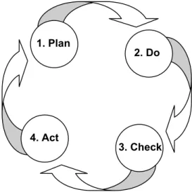
In the beginning of the work it was not decided which way to go to reach the goal. Therefore the methodology is a hard and big decision to make. The choice of methodological work process includes different activities that assure that the result corresponds to the objectives and scientific requirements. I have worked according to the PDCA cycle, visualized in figure 2 below. The work has been made iteratively and every loop has more or less, been built up by a PDCA cycle. The cycle starts in circle one, in the planning.
4. Act
3. Check 1. Plan
2. Do
Figure 2 shows the PDCA cycle, created by Deming6
2.1 Qualitative and Quantitative research
Qualitative research accepts that there is a range of different ways to interpret a phenomenon. The central in Qualitative research is to deepen the understanding of the studied area. By e.g. unstructured interviews is the enhanced understanding of the context reached. Qualitative data has the advantage that it gives a description of the situation that considers social processes and contexts.
Quantitative research is often performed by questionnaires, controlled experiments or by collecting data from a case study. The data is often expressed in figures. The quantitative data is structured and formalized. To use quantitative methods the
researcher has to do careful demarcations of what to be investigated. Quantitative data is measurable data. 7,8
6http://www.quality.enr.state.nc.us 2004-02-27
7 Experimentation in software Engineering, (2000) Wohlin C. (red.) 8 http://www.writing.colostate.edu 2003-11-24
2.2 Research Design
910Based on the purpose of the investigation there is a choice of research design. Several methods to apply and three normal research methods that often are used are survey research, case study and field experiment.
Survey research is the method of gathering data from respondents thought to be representative of some population. The gathering is mostly made by interviews or questionnaires and can be of qualitative or quantitative art. The results from a survey research are of descriptive and explicatory art and they are generalized to the
population from which the sample was taken.
Case study research is an observational method – it is an observation of an on-going project or activity. The study is made in a smaller group and the research is deeper than in a survey research. Relationships not known from the beginning of the study are allowed to be studied and more variables can be discovered in a case study than in the survey.
Field experiment is normally made in a laboratory environment and provides a high degree of control. The key factors are identified and the objective is to manipulate one or more factors and control all other variables at fixed levels. This manipulation is measured and the quantitative data is collected and statistically analysed.
2.3 Data collection method
11The data collected in the research can be collected in different ways. Questionnaires and interviews are often used, but observation is also a way of gathering information. Interviews are when questions are asked, between four eyes, by telephone or written. The interviews have different structure depending on the purpose of the interview. Interviews that are of explicatory art are unstructured and are more like discussions where the interviewee often leads the discussion – not the interviewer.
Semi-structured and Semi-structured interviews are made when the interviewer has more specific questions. Then an interview template is often followed.
Observations are made when the researcher observes a group or a process. An advantage is that the observer is able to and draws his/her own conclusions on how things are and not have to rely on someone else subjective facts. The observation can only study present behaviours – not the past or the future. Neither can knowledge, values or opinions be studied.
2.4 Way of attacking the problem
After the first step, which was an information-gathering step, methodically explained in chapter 2.4.1, the largest methodical step had to be chosen. As I could see it, I had two ways to choose between, and I chose a combination of the two ways. This will be explained in chapter 2.4.2 and 2.4.3.
9 Experimentation in software Engineering, Wohlin C. (red.) 10www.writing.colostate.edu 2003-11-24
2.4.1 The first methodical phase
I was not given a specific problem formulation when I came to Tetra Pak to work with this thesis. I was given free reins, but as a newcomer (almost), at Package Prototyping and in the prototype producing area, I had to make a thorough information gathering before demarking the area and deciding the problem formulation and the objective. This information gathering was executed as a survey. I was in the laboratory observing how the work was performed. I also sealed packages and tested the different sealing rigs. Many qualitative unstructured interviews, with people from different areas and with different knowledge, were made.12 This survey research was made to get an overview of the problem situation and an understanding of how the manufacturing process worked.
After this survey, the problem formulation and the objective was set in accordance with the instructors at Tetra Pak and the tutor from LTH.
Now more controlled tests in the laboratory were made, this to get a better knowledge of how the production worked – its advantages, disadvantages and limitations. This was a very thorough work to do; many rigs were tested in different ways. I did small factorial tests; both to get the practical experience of factorial tests, but also to get more knowledge about the rigs.
Simultaneously with the practical work a literature study was made where databases, libraries and the web were searched. Information about sealing technologies,
qualitative improvement work and design of experiments were the most interesting areas. This was done to get an understanding of the process in-house and the literature
study was to wider conceptions and to find applicable improvement tools to use in the organisation. This phase was the most time-consuming part of the work – but essential. To be able to implement new ideas and ways of working is it necessary to have a good knowledge of the technical process and how the views and opinions in the laboratory are. The work was relatively unstructured; this was for letting the persons being interviewed guiding me instead of me guiding them. At this phase of the work I just wanted them to tell me as much as possible about what they identified as problems. By the end of this phase the areas where the problems manly arise are identified. This first methodical phase was of qualitative art.
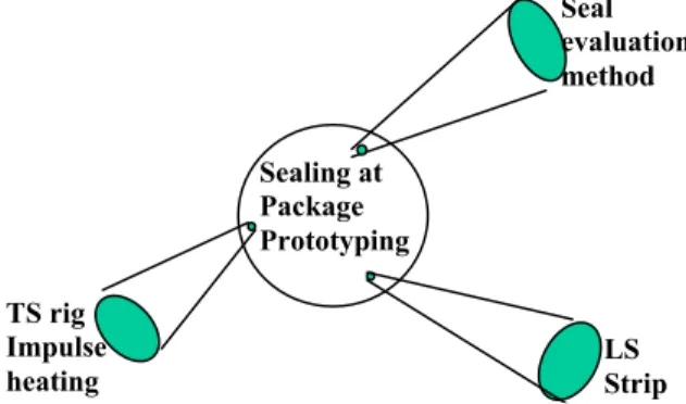
Figure 3 shows which areas of interest that was
chosen. The big circle represents the whole process that is studied in phase 1 and the spots that are identified as problem areas.
TS rig Impulse heating Sealing at Package Prototyping LS Strip Seal evaluation method
After this pre-phase more literature studies were made, now with focus on what was found as interesting areas (in the first phase). Design of experiments and different aspects of multi-factorial tests were studied. Quality improvement tools and methods were also studied, such as e.g. FMEA-analysis and Six Sigma.
12Interviews were made with Package Technicians, Method Developers and Group Manager at Package Prototyping. I also
spoke with staff from Sealing Technologies, with specialisation in different sealing methods. In addition to this interviews was made with people from other areas, material responsible at SCAP project, staff from Material Analysis, Material Development and Technical Package Development
There is no evident road to follow to reach the objective. As far as I can see there are two possible ways of attacking the problem: Either to do Experimentation in existing in-house equipment or to find the General best sealing. I will explain what the two ways mean and thereafter declare my choice.
2.4.2 Experimentation in existing in-house equipment
Experimentation in existing in-house equipment means to use the existing machine park in an optimal way and do experimentations in the rigs at the laboratory at
Package Prototyping. The advantage with this methodology is that the results are easy to apply in the production, but the disadvantage is that the result might not lead to a good seal. It is very likely that the rigs are not fully equipped and that some
parameters that would have an influence on the result are invariable at the rigs. There is also a risk that this experiment gives the best possible result.
Another disadvantage with this method is that some parameters that probably have influence on the result are invariable in the rigs at Package Prototyping. This might lead to an experiment that does not lead to as good result as it could have if more parameters were variable.
2.4.3 Best sealing generally
To methodically work with the best sealing generally means to do research and to generally find the best ways to seal particular material – without considering the existing machine park at Package Prototyping. This work would have been made mostly at Sealing Technology’s laboratory. The rigs at Sealing Technology have more variable parameters and greater variable width. This methodology is inductive and has the advantage that totally new information can come out from the experiment. The disadvantage is that it might be impossible to introduce the new methods in the existing machine park at Package Prototyping, the equipment at Sealing Technology is too complicated and expensive and it might be impossible to copy the other conditions to the rigs and the environment at Package Prototyping.13 ST has very skilled and specialized personnel working in the rigs, but the personnel at PP are more generalized and only temporary employees.
2.4.4 Chosen Methodology
I have chosen to set up the work in a middle course between the two ways explained above. If looked at the two methods individually my opinion is that the disadvantages overweigh the advantages. I strongly believe that a combination of these two lines is the best way of working in this specific case. In this way is it possible to get
knowledge from ST and their experienced and competent personnel but at the same time perform tests at Package Prototyping. In this way the work will reach further than in experimentation in in-house equipment but at the same time be applicable at Package Prototyping. There is a risk that the work is too complex and indistinct, but that can be solved by well thought-through demarcations and methodology. Meant by going the middle course is to theoretically learn and to search information in-house at Tetra Pak about sealing technology and at the same time do a lot of pre-tests at the
13 ST has other demands on their packages. They seal smaller batches than Package Prototyping with
laboratory at Package Prototyping to get the knowledge about the capacity of the rigs there.
Finally, when experiments have been made, I will give suggestions to PP what changes can be done at the rigs to reach better results and how to optimally use their own rigs. A positive addition to the work is if the tests easily can be replicated and used by the package technicians when new materials enter the prototype production and that a statistically test can be used to detect the best sealing parameters.
By choosing this middle course I have a thorough work had to be made. After discussions with the supervisors from Tetra Pak we decided that I should work this way and do as much as possible. A student from Tetra Pak’s Summer Work
Program14 can continue with working on some areas that might have not been finished in this work.
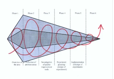
Figure 4 A model for how this report is built up methodically. The top light-grey field represents
theory studies; the dark field in the middle empirical studies and the light field represent analysis. The model shows the scope of the project is changed in differed phases in the project. The work is made iteratively through theory studies, empirical studies and analysis throughout the whole project. 1st phase is already made (and explained in chapter 2.4.1) when the decision of methodology is taken.
2nd phase. I was during this time working in the laboratory, producing and testing prototypes sealed in different rigs. I got the knowledge about the problems where the prototypes leaked. I also studied and investigated the underlying causes why the leakage arose.
3rd phase. In this third phase secondary data was collected (books and databases). I studied what tools and methods can be used for quality improvement.
4th phase. In this phase the aim was to make the chosen quality improvement tool to fit the environment – to customize it! I did, during this phase, work a lot in the
14 Summer work program is a program at R&D where master of science students are with projects
laboratory, partly simply to see how the environment there where, but also to slowly make to package technicians get used with this way of working. I realized that the greatest threat to my work was that the proposals I was to suggest would not be more than a paper-work and nothing used in reality.
5th phase is the implementation of the work. I made a presentation to all package technicians where I presented my work and gave an overhauled instruction on how the improvement work is to be integrated in daily production. After this group introduction I took a short individual introduction in the lab, showing the test equipment and the calculation tool.
6th phase. In this last phase I finished writing the report and gave suggestions to what future work might be needed in this area. I also wrote a guide to the person that will work with these matters in the summer work program this summer, which hopefully will guide that person into Package Prototyping’s world of quality improvement. I also made presentations – at LTH and Tetra Pak.
3 Theory
In this chapter theories on sealing techniques will be gone through briefly, to give the reader an understanding about the different techniques of how to heat the sealing material. Followed by this is theory of different manufacturing process choices and how this acts on different areas, e.g. rigs and demands on personnel skills. Finally theory of test methods will be overviewed. Knowledge in these areas is needed when working for fulfilling the objective.
3.1 Sealing Techniques
Sealing is done when the seal material is heated to, or higher than, its fusion
temperature and the two materials is bonded (united) together molecularly15. Sealing is done with different methods at Tetra Pak; all methods have same purpose – to heat the sealing material. The sealing depends on the sealing material – different materials have different properties. Sealing material used at PP and their different properties is described in Appendix C. The theory about how the sealing techniques that can be used at Package Prototyping, is explained below.
3.1.1 Induction Heating
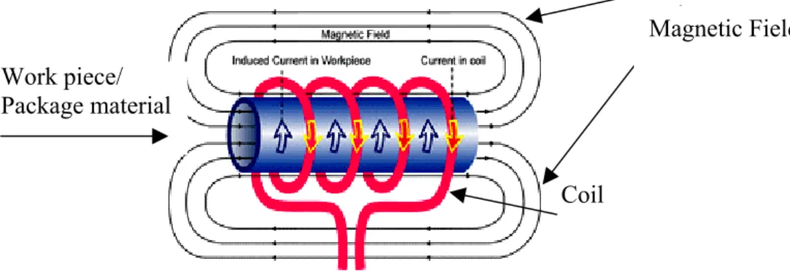
The work piece (package material) has to contain metal or other conductive material when heating with induction. An electromagnetic field, created by a coil, creates a current in the aluminium layer in the material, as shown in figure 5. The current causes heat in the package material, because of the resistance in the material.
Induction heating applies the heat on the inside of the package material and not from the outside, which is an advantage when heat loss is reduced (read more about heat loss when sealing in chapter 4.4).
As the figure shows an alternating current is passing through the coil, see figure 5, and this causes an electromagnetic field. When the work piece is put into the electromagnetic field a circulating current is created. This current flows against the resistivity in the material and causes heat.
Magnetic Field Work piece/
Package material
Coil
Figure 5 Schematically show how induction heating works16
15 According to Sealing Technology Department, Tetra Pak R & D 16http://www.ameritherm.com 2003-10-15
3.1.2 Impulse Heating
An electrical impulse is sent through a metal thread. The thread is normally of a material with a low coefficient of linear thermal expansion, e.g. copper. The thread is heated when the electrical current passes through it. An impulse-heating rig can consist of threads on one or both sides. The one-sided rig is only warming the package material from one-way and therefore higher temperature is needed to reach the sealing layer in the centre, than when the rig is two-sided. The heat is applied from the
outside of the material.
3.1.3 Constant Heating
A jaw is heated to a certain temperature and pressed down to the packaging material with a certain pressure.
3.2 Process Choice
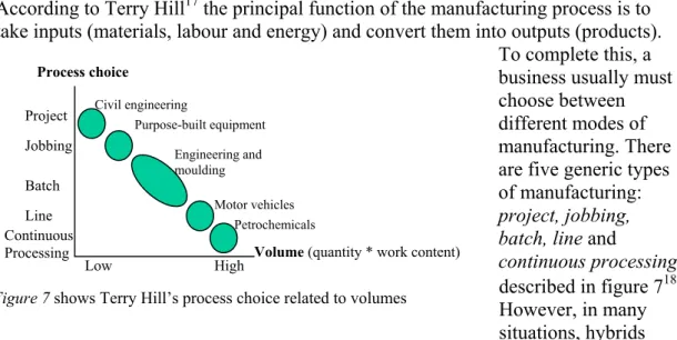
According to Terry Hill17 the principal function of the manufacturing process is to take inputs (materials, labour and energy) and convert them into outputs (products).
To complete this, a business usually must choose between different modes of manufacturing. There are five generic types of manufacturing: project, jobbing, batch, line and
continuous processing, described in figure 718. However, in many situations, hybrids have been developed that blur the edges between one process and the next.
Process choice Petrochemicals Motor vehicles Engineering and moulding Purpose-built equipment Civil engineering Low High Line Continuous Processing Batch Jobbing Project
Volume (quantity * work content)
Figure 7 shows Terry Hill’s process choice related to volumes
Project Projects are large-scale, unique and complex products that are provided under project basis. Examples include aerospace programmes and civil engineering projects.
Jobbing A jobbing process is used to meet unique order requirements from customers. The product that is produced is of individual nature. The supplier has to interpret the customer’s design and this needs to be made of skilled employees whose experience in this type of work is an essential facet of the process. The production is one-off and this means that the product will not be required again in its exact form. If the same product is required again will the demand be irregular with long time between orders. For this type of process is it normally not advisable to invest in e.g. fixtures or jigs.
17 Hill, T. Manufacturing Strategy (2000) 18 Ibid
Batch When producing in batches are similar items provided on a regular basis. The volume is larger than in jobbing production. In a batch process a wide range of volumes can be manufactured. The batch procedure divides the manufacturing task into a series of appropriate operations, which together will make the products involved.
Investments in jigs and fixtures will be paid off if the total product output of the time is high enough.
Line With further increases in volume is the process dedicated to a single product or a given range of products. In a line process products are passed through the same sequence of operations. Changes outside the prescribed range of options (which can be very wide, for example, with motor vehicles) cannot be accommodated on the line itself.
Continuous With continuous processing, a basic material is passed through Processing successive stages or operations and refined into one or more products.
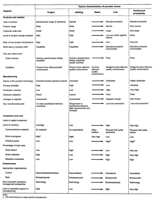
Two features that are typical for continuous processing are firstly very high volume demand and secondly that the materials involved can be moved easily from one part of the process to another. The high-volume nature of the demand justifies the very high investment involved. Figure 8 indicates how different aspects, as products and markets, manufacturing, investment and cost and infrastructure vary meaning with different process choices. The rate of quantity of products produced/employee rises as moving right in figure 7. Personnel skills, investment in machine equipment and automation degree is all depending on what kind of process choice the business has. In project and jobbing, products are only made for customer order. In batch, decisions are to cumulate demand, or make to stock, relate to appropriate volumes for the process investments in place and the actual sales-order volumes required.
Figure 8. The most important business implications on the process choice19
3.2.1 Special, standard or customized products
It is important to distinguish between different types of products whether they are special, customised or standard products. A special product is a one-off product and
the product will not be required again in its exact form. A standard product is the opposite – the demand for the product is repeated and this warrants investments. A customized product can be either standard or special, but refers to the customer’s specification. An example from Manufacturing Strategy (2000)20 is the soft drink can that is a customized standard product.
3.3 Quality
The word quality is an often used word with different meanings. Different people have over the years set different definitions of quality. Taguchi’s common used definition of quality is: “Quality is the loss imparted to society from the time the product has shipped”.21 Taguchi takes the customers view and refers quality problems encountered before the shipping of the product as costs. This definition differs from other quality definitions. The more traditional mentality of what is considered good quality says that a product is either good or it isn't, depending or whether or not it is within the specification range (between the lower and upper specified limits). With this approach, the specified range is more important than the target value.22 Quality can also be defined from the customers view, depending on the demands and
expectations the customer has on the product or service offered. Bergman and Klevsjö propose the definition “The quality of a product or a service is its capacity to satisfy, or exceed the customers’ expectations and needs”.23
Terry Hill discusses the quality approach in the book Manufacturing Strategy (2000) 24. A company can have a reactive or proactive approach to quality. The former has the emphasis to detect faults. The latter prevents faults, i.e. to try to make products right the first time. This is achieved by defining which factors have an affect on the performance of the product and proactively working for optimizing the outcome of the process.
According to Terry Hill is quality control, in project and jobbing processes, responsibility by the person responsible for the manufacturing plus supervisory support. The making and quality conformance tasks are normally integrated in the skills of the person. Generally does the persons working in project and jobbing processes have more responsibility and therefore does these types of processes acquire more skilled personnel.
3.4 Experiment Planning
“Experiments are launched when we want to control over the situation and want to manipulate behaviour directly, precisely and systematically.”25
Design of experiments is described in many books that investigate Quality Improvements. The theory in this chapter is based on books by Olausson and Rydebring26, Bergman & Klevsjö27, Bergman28, Bódizs & Hansson 29 and Wohlin
20 Hill, T. Manufacturing Strategy (2000)
21http://www.doeqi2.com/taguchi.htm 2003-02-10 22Ibid
23Bergman, B, & Klevsjö, B: Kvalitet: från behov till användning (1995) 24Hill, T., Manufacturing Strategy (2000)
25Wohlin, C. (red.), Experimentation in software engineering. (2000)
26Olausson, M. & Rydebring, O., Statistisk försöksplanering; faktorförsök (1992) 27Bergman, B. & Klevsjö, B., Kvalitet från behov till användning (1995)
(red.)30. To be able to base decisions on facts and to carry through quality
improvements it is necessary that data is systematically collected and evaluated. Well-planned experiments provide knowledge about which construction parameter values to choose to get a
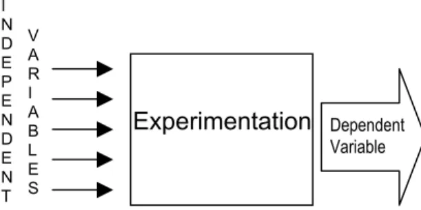
product or process as good as possible. As figure 9 indicates are the independent variables are the input to the experiment. The independent variables can be noise factors and factors that can be varied. The factors that have an effect on the result of the experiments are varied systematically in different ways. I N D E P E N D E N T V A R I A B L E S Experimentation Dependent Variable
Figure 9. How the dependent and independent
variables depend on each other
3.4.1 Simple Comparative Tests
To execute Single Comparative Tests is a simple and logic way of conducting
experiments. One factor at a time is varied and the other factors are kept at a constant level. This compares the two levels of each factor in a controlled way. With this method it is possible to see if one factor has an impact on the result of the experiment or not. If two factors have an interactive effect on the result this method is not to be used and will not give an optimum result.
3.4.2 Multi Factorial Tests
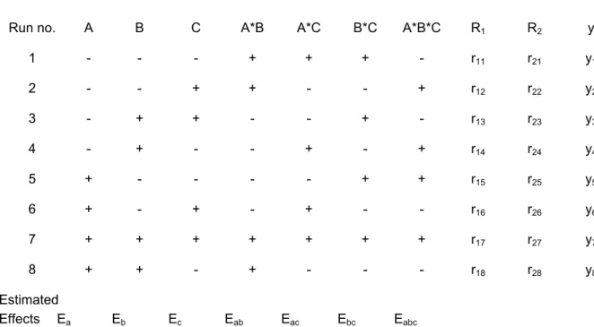
In Multi Factorial Tests the variables are changed systematically between two or more levels. The outcome of this method describes and gives knowledge about the process. The method can also be used to optimise the exchange in a process or to decide which construction factors make a product fulfil different demands, e.g. quality, working environment or performance. We can also see if there are any interactions between the independent variables. How big impact the variables and interactions have on the result is also detected when using this method. The variables are changed according to a schedule and the effects are estimated statistically. A problem with multi factorial tests is that the number of test runs grows exponentially with the variables. If n variables are tested in k levels, nk tests will be executed. Figure 10 is a design matrix that acts as an example with three factors (A, B and C) in two levels (- and +), which gives 23 = 8 test runs. The possible interactions are A*B, A*C, B*C and A*B*C. The sign of the interactions are calculated as products of the factors.
28Bergman, B., Industriell Försöksplanering, (1992)
29Hansson, M & Bódizs, R., Kvalitetsförbättring med försöksplanering (1999) 30Wohlin, C. (red.), Experimentation in software engineering (2000)
Run no. A B C A*B A*C B*C A*B*C R1 R2 y 1 - - - + + + - r11 r21 y1 2 - - + + - - + r12 r22 y2 3 - + + - - + - r13 r23 y3 4 - + - - + - + r14 r24 y4 5 + - - - - + + r15 r25 y5 6 + - + - + - - r16 r26 y6 7 + + + + + + + r17 r27 y7 8 + + - + - - - r18 r28 y8 Estimated Effects Ea Eb Ec Eab Eac Ebc Eabc
Figure 10 A schedule of a multi factor experiment with three parameters in two levels
The results of the experiments are y. In this example is only one repetition of the result made. To have a statistically more secure result is often more tests made. First the mean result is calculated. The estimated effect of the A-factor, Ea are calculated by summing the mean results, yi , with the signs in the A-row, divided by four. ¼(-y1-y2-y3-y4+y5+y6+y7+y8). In same way are the other effects estimated. To see if the estimated effect has an effect in reality we need to consider the random variation in the experimental results. Firstly the variance, s2, is calculated by √(y1i-y2i). The mean of the variance, called sp, is calculated by ∑sj2/k. The effective variance is calculated seff2 = 4sp2/N, where N is the total number of tests made (in this example N = 16) and is used to see in what area the non-significant effects are. I have used the 3σ-method to see which effects have significant effect on the result. The 3σ-method means that all effects that are greater than +3seff2 or smaller than -3seff2 are statistically significant with 99.98 % certainty. 31,32
When all possible combinations of factor levels are investigated is it done by Full Factorial Experiment. If there e.g. is a two-level experiment and three factors is it a 23-experiment with 23 = 8 number of runs. The number of rows grows exponentially with growing numbers of factors.
3.4.3 Reduced Experiments
When the risk of interactions is small reduced experiments can be executed. When performing reduced experiments some effects will be overlapping, that is that one interaction between two factors can be mixed with an effect of one factor. This causes that it will not be possible to differ between these effects. Therefore reduced
experiments are best used in the beginning of an experimental series when many factors are to be investigated whether they have an impact on the result or not. Not
31Olausson, M. & Rydebring, P., Försöksplanering i Utvecklingsarbetet (1992) 32Magnusson, K., Six Sigma (2000)
interesting effects can directly be screened out and new experiments can be made with the probably significant factors found in the reduced experiment.
4 Empirical studies
This chapter will give the reader a survey of the production process at Package Prototyping and the factors that have an influence on the process. All information in this chapter will not be further investigated in the report, but the information is important for the reader to get an understanding about the process. I will give a background to the manufacturing process, but also describe how the package material is built up and how the seals are made. Finally, an overview of
manufacturing strategy and quality strategy within Package Prototyping will be made.
4.1 Background
The production at Package Prototyping has different customers, as described in chapter 1.1.1, and the prototypes are used for different purposes. Lately more orders have been made from TPD for technical and functional tests. The demands on these tests are different from customer or consumer tests. When prototypes are made for being used in technical tests is it desirable to make the prototypes in a way as similar as possible as it would have been made in a filling machine. On the other hand, when the prototypes are made for customer or consumer tests, “cheating” is allowed; this means that a prototype doesn’t have to be made in the same way as it would have been in the filling machine. Cheating can be made through using another material than in the real production or filling the sealed prototype with e.g. silicone to tighten possible leakage.
4.1.1 Seals
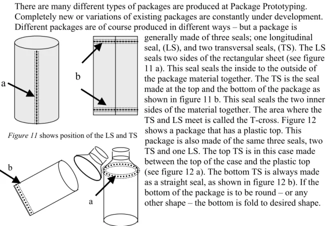
There are many different types of packages are produced at Package Prototyping. Completely new or variations of existing packages are constantly under development. Different packages are of course produced in different ways – but a package is
generally made of three seals; one longitudinal seal, (LS), and two transversal seals, (TS). The LS seals two sides of the rectangular sheet (see figure 11 a). This seal seals the inside to the outside of the package material together. The TS is the seal made at the top and the bottom of the package as shown in figure 11 b. This seal seals the two inner sides of the material together. The area where the TS and LS meet is called the T-cross. Figure 12
shows a package that has a plastic top. This package is also made of the same three seals, two TS and one LS. The top TS is in this case made between the top of the case and the plastic top (see figure 12 a). The bottom TS is always made as a straight seal, as shown in figure 12 b). If the bottom of the package is to be round – or any other shape – the bottom is fold to desired shape.
b
a
Figure 12 A package with a plastic top and round bottom
a b
4.1.2 Manufacturing Process at Package Prototyping
Figure 13 Manufacturing
Process at PP
The manufacturing process at Package Prototyping is different from how packages are made in “real” production in the filling machines. Apart the affect the human hand influence on the outcome and that different materials and methods might be used, are the processes at Package Prototyping and in the filling machines not the same. Generally, the two different processes can be described as in figure 13 and 14 where the former figure describes the process at Package Prototyping. The production varies depending on the package produced, but the general way of producing will be described here. The material is measured and cut by hand (2). If the material is creased this is made between step 2 and 3. Also the following step (3) is made by hand in a strip applicator rig. The cut material is placed under the jaw and a roll of strip material is rolled out and placed on the edge of the material. The 4th step in the process is to make the LS in the crocodile jaw if non-aluminium material is used, or in the loose induction rig if the material contains aluminium foil. The tube is formed with help from the vacuum positioner in the rig if impulse heat is used. There are some exceptions to this – e.g. the plastic tops in carton packages. At Package Prototyping the tops are vacuum formed and not injection blow moulded as in “real” production. The tools for injection blow moulding are expensive and there is long lead-time to get them, but for vacuum forming can tools be manufactured in-house or be bought form a supplier with short lead-time33. There is a vacuum former in-house to produce tops.
4.1.3 Manufacturing Process in filling machine
1. Material on a roll 2. Strip is applied 3. A tube is formed 4. LS is made 7. 2nd TS is made 5. 1st TS is made 6. Filling is made Package Prototype 1. Material on a roll 2. Material is cut 3. Strip is applied 4. LS is made 5. 1st TS is made 6. Filling is made 7. 2nd TS is made Package Prototype
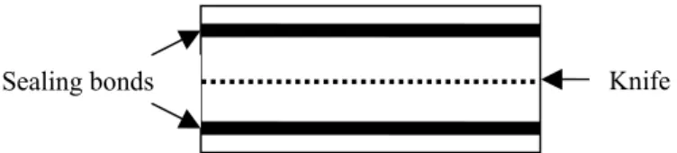
Figure 14 generally shows how the production process is in the filling machines. The material enters the machine from a roll and the first thing made in the machine is the application of the strip. This is made by hot air or induction heating that heats the sealing layers and rolls that puts a pressure on the strip seal. The 3rd step is the forming of the tube and after this is the 4th step, the LS, done. The LS is sealed in different ways in different machines, but can be made with hot air or induction heating. The 5th, 6th and 7th step are done integrated. The top TS of one package is made at the same time as the bottom TS is made for another package. There is a knife in the tool that cuts the two packages apart. The sealing tool is schematically pictured in figure 14.
Figure 14 Manufacturing process in filling machine
33 A new model mill is recently bought. It is possible to make tools for vacuum forming in this mill –
Knife Sealing bonds
Figure 15 How the sealing jaws looks like in a filling machine. On the anvil is
a rubber with particular hardness depending on the type of material sealed.
4.2 Package structure
In this section, interesting facts not discussed in 4.1.2 or 4.1.3, about the package structure, will be described.
4.2.1 Packaging Material
Different attached material layers build up the packaging material. Every layer has a different task. The sealing layer is the inner and outer layer of the material and is formed by a type of PE, PP or PET (see Appendix C). The core material is paper, carton, chalk or glass. This core material has the task to prevent oxygen and/or UV light to penetrate the package and affect the content. The packaging material can be more or less compressible. Material that is carton-based is more compressible than material without carton.
4.2.2 Creasing and Strip
There are some implications for paper- or carton based material packages. Thicker package materials need to be treated in a different way than thinner and softer package materials. Thicker materials are often folded to a certain shape (and creased before folded for making a pattern). The crease makes it easier to fold and makes the shape more stable.
When the package material is carton- or paper-based a strip is applied on the edge of the material where the LS is to be made. This edge is the only edge of the sheet that is to be found on the inside of the package. The strip is sealed on the material and protects the “open” carton or paper end to get in contact with the filling. Otherwise liquid will penetrate through the carton or paper and loose up the material from the inside. The strip can be applied in two ways on the sheet, as shown in figures 16, a and b. The strip in figure 16 a is first sealed on one side of the material and then folded around the edge of the sheet and sealed one more time on the other side. In figure 16 b the strip is applied on the inside of the material, where arrow number 1 points. Then the LS seals the rest of the strip on the inner side of the other part of the material (see arrow number 2).
a b
1
Figure 16 Indicates how a) how a folded strip is attached to and b) a strip applied on the inside of the
package material
4.3 Rigs
The machine park at Package Prototyping contains four types of sealing rigs: ultrasound rig, induction heating rig, constant heat rig and impulse heat rigs. A description of the rigs and what changes and additions have been made or are to be made to the rigs will be described.
4.3.1 Impulse LS rig
The rig for longitudinal seals is called crocodile jaw – because of its looks. It has heating coils at two sides and the jaws are pressed together with a pedal. When the jaws are pressed together the impulse starts and sealing is made. The jaws can
preferably remain being pressed together a short time after sealing – this is for letting the material cool down. A problem with this rig is that it has no cooling system, which leads to a heating of the rig when used continually (when large batches of many packages are to be produced). The rig only has one adjustable parameter – time. The pressure can be changed by pressing harder or softer on the pedal or by pressing the jaws together by hand. This isn’t a controlled way of varying the pressure (but is used anyway). The sealing jaws are covered by a layer of Teflon tape, which softens the jaws and prevents the sealing material from sticking to the jaw. The Teflon tape can withstand temperatures to maximum approximately 300°C34. It is of great importance to the seal quality that the jaws are in a good condition, that the heating band is without defects and that the Teflon tape is not burned or damaged in any way. The sealing bands have to be maintained by changing sealing bands or changing Teflon tape when necessary. A vacuum positioner has been added to the rig. This positioner is a good help when the sheet is formed to a tube; because the vacuum makes the edges of the sheet stay in a certain position and therefore is there no use to patch the sheets up together with e.g. tape. The vacuum positioner works by a compressed air system.
When many packages are made this rig is very slow. It gets too hot and the time the package technicians have to wait to let the rig cool down is longer than the actual time the rig is sealing. As described above is the pressure constant, and this constant level is relatively low. It would be desirable to have a LS impulse rig that has variable pressure and a cooling system. If this would be introduced would it also be possible to evaluate the LS via design of experiments (in a way similar as the experiment this report propose that the TS is evaluated).
4.3.2 Impulse TS rig
The rig for transversal sealing has for the moment two adjustable parameters, time from 0 to 1,2 scale divisionsand temperature from 10 to 70 scale divisions that has been calculated to a corresponding temperature from 170°C to 310° C. It is possible to change the pressure by adding or removing washers. The pressure is also varying depending on the thickness of the material. It would be of interest to be able to measure the jaw force. Therefore a load cell has been ordered and a rebuilding of the rig that allows us to easier increase and decrease the jaw pressure is planned. After this change the impulse TS rig will have three measurable parameters, instead of two.
The rebuilding will make it easier to vary the pressure, than it is with washers. The new system will work by fastening and loosing four screws on the rig. A cooling system is also recently added to the rig, to prevent heating of the jaws, which leads to long time of waiting between the sealing. The anvil is provided with a rubber (see and read caption of figure 15). The rubber in the rig has a hardness of approximately 95 Shore, but there are three new rubbers with a hardness of, 90, 76 and 65 Shore. It is relatively easy to change rubber in the rig.
4.3.3 Induction LS rig
The LS induction-heating rig is a “loose rig” that contains of a tool where the heat is developed and an anvil that has the same diameter as the case will have. The sheet (see figure 13, step 4) is wrapped around the anvil. There is an overlap of
approximately 6-20 mm. The tool is adjusted/put on top of the overlap and a pedal is pressed down and the sealing is made. Adjustable parameters in this rig are sealing time and voltage. The pressure is applied by hand and it is important that the tool keeps still and that a constant pressure is applied. The pressure will be kept for a few seconds until the seal cools off and gets rigid.
4.3.4 Induction TS rig
The TS induction-heating rig has been changed. Still the old is rig used, but the new one will be taken into use shortly. The new rig will have 3 variable parameters, namely effect, pulse time and pressure. I have not made any tests at all in this rig because of the rig change.
4.3.5 Strip Applicator
The strip applicator seals the strip to the package material with constant heating. There are different types of strips to use. The strip shall have the same material in the
outer layer as the package material has in the sealing layer or the layers shall have a similar fusion temperature. The temperature can be varied in a wide range. Pressure can be varied with the air pressure from 3 bar to 10 bar and time can be varied in a wide range. Figure 17 shows how the strip is applied in the rig. The package material is placed in the rig and the strip is carefully
placed on the edge of the material. How the sheet and strip are placed is of great
importance of how the strip is sealed. The accuracy in the placing of package material and strip is important. If the placing is varied as little as 1 mm the misplace can cause leakage.
Strip Package Material
Heating Jaw
Figure 17 The strip is placed on the edge of
the material and the heating jaw is pressed down for a certain time to seal the strip
The rig has a sealing width of 2 mm (l in figure 18). The strips are normally between 6 and 10 mm wide.
Package Material Strip
l
Figure 18 Shows the measures when the strip is sealed in the strip applicator
4.4 Sealing – temperature loss
How the other layers in the materials handle high temperatures varies from material to material. Known is that too high temperatures can destroy the package material – polymers can become brittle and paper and carton might be burned.35 To make a good seal, the sealing layer needs to be heated up to its fusion temperature. How is the heat transferred to the sealing layer in different sealing methods and rigs?
Tfusion Tmax
Tmax Tfusion
Figure 20 A TS made in
a one-side heating jaw
Figure 21 A TS is
induction heated
Figure 19 A TS sealed in
a two-way heating jaw Figure 19, 20 and 21 schematically indicates where the heat is applied and how the heat is transported to the sealing layer. The figure shows a cross-section of the package material when a TS is to be made. The grey layers are the sealing layers, the white paper or carton and the black layer is an aluminium layer. Figure 19 shows a TS, where the heat is applied in a two-way heating jaw. The difference between Tmax and Tfusion is lower in figure
19 than in 20. Figure 20 shows a one-sided heating jaw and more heat has to be applied to reach Tfusion in the centre where the sealing layers are. In figure 21 is induction heating used and the heat is created in the aluminium layer. This layer is next to the sealing layer and therefore is not as much heat needed as in the two former figures. Induction heating has its advantage because of this. The “shorter” way the heat has to travel – the easier is it to give the correct levels of the
temperature, time and pressure parameters. 36 Tfusion
Tmax
4.5 Quality in production
What attitude does Package Prototyping have on quality? Two students worked with a quality project the summer of 2003 within the organisation. This report mostly
handled the “soft” aspect of quality – the communication and how engagement could be risen (or kept at a high level) among the package technicians. That ended in a more structured way of working, e.g. with meetings with the ordering person at every order point and a final meeting after every delivery. The purpose of this was to get the package technicians more involved in the projects and to get knowledge about what the prototypes are to be used for and the final meeting was for learning from what
35 According to Charlotte Friberg, ST
went well and what went wrong. This report has made the package technicians more involved in and aware of the orderers purpose with the prototypes, but has also made the work in the laboratory more structured. Every package technicians are responsible of their own project and handle the planning and material orders themselves. This report has given the package technicians a higher level of responsibility from this “softer” quality aspects and a part of the purpose with this project is that the more “hard” aspect of quality will be accounted in the tasks for the package technicians.37 Today, no quality tools are used in the production at Package Prototyping. Neither is any quality evaluation method systematically used. When setting parameters at the different sealing rigs, different technicians use different ways. Some are using the tongs method (read more about this is chapter 4.6.2) – but too often no methods at all are used.
4.5.1 Quality demands in production
The four main purposes for the prototypes are: • Showing tests
• Quality tests • Quantity tests • Technical tests
For showing and quality tests the demands are different than for quantity and technical tests. For the two former tests is the appearance of the package most important, and for two latter tests are the technical specifications most important. When appearance is the most important matter this can allow the package producers to “cheat” when producing these prototypes. This means that the packages don’t have to be made in the way explained in chapter 4.1.2, silicon or wax tightening can be made inside the package. The latter types of packages explained are for technical and quantity tests and these types of packages are to be made in a, from the orderer, specified way. In this case SA is often the orderer and their knowledge of sealing is high, but they cannot always apply their knowledge in Package Prototyping’s rigs.38 The quality demands on the prototypes differ depending on the purpose. Every internal project that has a need of prototypes has a responsible package technician at Package Prototyping. This makes the communication better, when the orderer and the producer know each other and the purpose for the specific order will be known. This is of great importance when the purpose can differ very much and the production process is different for depending on the purpose of the prototype.39
There are no standardised quality evaluation methods used in the prototype production. Neither is a definition of quality defined at Package Prototyping.
37 According to one of the authors of the report, Henrik Lindell 38 According to Göran Dahl, group manager at Package Prototyping 39 Ibid
4.5.2 Customized or standardized products
The orders made from the internal customers are non-standard. We might say that they are customized products, that is that the packages are of a particular shape and size, but have a customization in e.g. décor. Normally, customized products can be made to stock and the customization can be made at a late stage in the production. This is not the way it is at Package prototyping. The customization is made as a first step in the process – the customization is very often the package material or décor and that is the material used. Therefore, no products can be made to stock. Special
products are products with non-repeatedly demand. I define some of the products as special and some as customized, where the latter are the products that are produced in the batch production and the former in the project production.
4.6 Manufacturing design at Package Prototyping
The package technicians producing the prototypes are temporary employees, employed for 2 to 12 months. No education is required for this job. For the moment there are 6 package producers employed and two are working extra when the demand of prototypes is high.40
The mode of manufacturing in the laboratory at Package Prototyping is according to me, a hybrid between jobbing and batch. Jobbing is, as explained in chapter 3.3, used to meet unique order requirements from customers. It is not often a totally new package is made at the laboratory, but it is of great importance that it is possible to make totally new packages. The equipment is flexible and general. This nature of equipment is very suitable when new products are made, or when the product properties are changing. On the other hand the production is not fast and it is not appropriate to produce large series of products. This is because the great deal of handwork that has to be made. In this type of production, when the equipment is general and flexible and when the level of automation is low, the skill of the worker play a greater part of the quality of the result than if the production has a high level of automation and a dedicated equipment. Few investments have been made to specialise and dedicate the equipment for special products. Some prototypes made are of typical batch production. Batches are of sizes from 10 to 350 products. There are series made with more than 10 batches of 300 prototypes in each batch and where the difference between the batches are only a slight change in some material property. The problems arise when big batches or series of batches are made in the flexible and general equipment. There is hard to achieve repeatability as good as in “real” production (in filling machine).
4.7 Design of Experiment
As the objective indicates we want to get knowledge about the manufacturing process and to design experiments so that the result will give us the knowledge about how to make better seals in the production. These two parts of the objective can be reached by Design of Experiments, (DOE), with factorial tests. According to Bergman41 purposes with planned experiments are to
40 Ibid
a) Decide construction parameters for a product or process parameters for a manufacturing process, so that they fulfil given demands, such as e.g. performance
b) Create knowledge about the influencing factors when discussing product planning, industrial research and development and when working with continuous
improvements
c) To develop a solution for quality problems
d) To improve a process / to enhance the result of a given process
All this four purposes are interesting for Package Prototyping and therefore will DOE be used.
4.7.1 Test Design Variables
The independent variables are the input to the experiment as pictured in figure 9. The independent variables can be noise factors and factors that can be varied. The factors that have an effect on the result of the experiments are varied systematically in different ways. Which factors to be varied and how the levels are to be set is determined by preliminary studies and interviews made with people at Sealing Technology and Package Prototyping. Through the preliminary studies I came to the conclusion that the independent variables that are to be varied in the experiments are different for different methods and these are described below. Noise factors are the factors that cannot be varied; examples of noise factors are manufacturing variations, environmental variations and wear. The independent variables (here rig parameters) are to be chosen so that the product will fulfil the demands and that the noise factors will not have significant influence on the result.42
Impulse Heating TS: • Temperature • Jaw force • Impulse Time Impulse Heating LS: • Impulse
• Jaw force (manipulatively)
Induction Heating TS:
• Weld Pulse (Time) • Pressure
• Power
Induction Heating LS:
• Weld Pulse (Time)
There are other factorsthat have an impact on the result, the dependent variable, which I don’t have influence on – noise factors. An Ishikawa diagram was drawn – together with people from the Package Prototyping. The Ishikawa diagram is similar in all sealing methods – but there are some differences. Appendix A shows an Ishikawa diagram where all factors that might influence on how a seal made in the TS impulse sealing rig.
4.7.2 Existing test methods
Many measure methods are established within the company. I have been at different departments within Tetra Pak R & D looking at the test methods they use. I also made interviews with different people with knowledge in this area. I will here give a
description of the test methods I have considered.
Ink Test
The package is cut in middle and a few drops of coloured ink are put on the T-cross, from the inside of the package. The ink will soak through the material if there are pores or holes and a colour will occur on the outside of the package. There are three types of inks to use, red, blue and green ink. The red ink is ethanol-based and has a high capillarity. It is used on paper- or carton-ethanol-based material. The blue ink is used on the same materials, but has a lower capillarity because it is water-, not ethanol-based. The green ink is based on propane alcohol has the property that it is easy to detect wholes and irregularities in seals in transparent plastic material that don’t contain carton or paper.
Advantages: The method shows clearly where the seal is bad. It is easy to use and is a cheap method.
Disadvantages: This test results in a tight or leaking seal – not in an analogue scale.
High Pressure Ink Test
This method works as the Red and Blue Ink Test but the a few drops of the ink is poured in a half package that is set in a tool and a certain pressure is applied. When the ink is seen on the outside of the package is there a leakage.
Advantages: A pressure is added and a measure when the first leakage appears.
Disadvantages: It is quite a slow test, is takes about 2 minutes per package half to perform. There has to be completely tight in the holder in the tool where the package is attached. There is a problem to fix the thinner (and not so stiff) materials in the tool. Previous tests