2012:31
Report number: 2012:31 ISSN: 2000-0456Available at www.stralsakerhetsmyndigheten.se
Decommissioning of the Nuclear
Reac-tors R2 and R2-0 at Studsvik, Sweden
– General Data as called for under
The report describes the plans for decommissioning of the nuclear research and material test reactors R2 and R2-0, situated at the Studsvik site in Sweden. The purpose of the document is to serve as information for the European Commission, and to fulfil the requirements of Article 37 of the Euratom Treaty. According to Article 37, each Member State shall provide the Commission with such general data as will make it pos-sible to determine whether the planned activities are liable to result in radioactive contamination of another Member State. The report repre-sents a revision of a report that earlier was presented to the European Commission, SSM Report 2009:01.
2012:31
Date: August 2012Report number: 2012:31 ISSN: 2000-0456 Available at www.stralsakerhetsmyndigheten.se
Decommissioning of the Nuclear
Reac-tors R2 and R2-0 at Studsvik, Sweden
– General Data as called for under
1
Contents
Introduction ... 3
1. The site and its surroundings ... 6
1.1 Geographical, topographical and geological features, land use and distances to neighbouring Member States ... 6
1.2 Hydrology ... 8
1.3 Meteorology ... 9
1.4 Natural resources and foodstuffs... 9
2. The installation ... 10
2.1 Brief description and history of the installation ... 10
2.2 Ventilation systems and the treatment of gaseous and airborne wastes ... 13
2.3 Liquid waste treatment ... 13
2.4 Solid waste treatment ... 15
2.5 Containment ... 15
3. Release of airborne radioactive effluents in normal conditions ... 16
3.1 Authorisation procedure in force ... 16
3.1.1 The Environmental Code ... 16
3.1.2 Legislation on Radiation Protection ... 16
3.1.3 Legislation on Nuclear Activities ... 17
3.2 Technical aspects ... 17
3.3 Monitoring of discharges... 18
3.4 Evaluation of transfer to man ... 19
3.4.1 Models and parameter values ... 19
3.4.2 Estimated exposure levels in other Member States ... 20
4. Release of liquid radioactive effluents under normal conditions .... 21
4.1 Authorisation procedure in force ... 21
4.2 Technical aspects ... 21
4.3 Monitoring of discharges... 22
4.4 Evaluation of transfer to man ... 22
4.4.1 Models and parameter values ... 22
4.4.2 Estimated exposure levels in other Member States ... 24
5. Disposal of solid radioactive waste ... 25
5.1 Categories of solid radioactive waste and estimated amounts ... 25
5.2 Processing and packaging ... 25
5.3 Storage arrangements ... 26
5.4 Radiological risks to the environment, precautions taken ... 26
5.5 Arrangements for the movement and destinations of classified waste transferred off-site ... 26
5.6 Criteria for contaminated materials to be released from the requirements of the Basic Safety Standards, for disposal, recycling or reuse ... 27
5.7 Envisaged types and amounts of released materials... 27
5.7.1 Metal scrap ... 27
5.7.2 Waste for disposal on municipal dump sites or reuse as filling material ... 28
6. Unplanned releases of radioactive effluents ... 29
6.1 Review of accidents of internal and external origin which could result in unplanned releases of radioactive substances ... 29
6.2 Reference accidents taken into consideration by the competent authorities for evaluating possible radiological consequences in the
event of unplanned releases... 30
6.3 Evaluation of the radiological consequences of the reference accidents ... 30
6.3.1 Releases to the atmosphere ... 30
6.3.2 Releases to water ... 31
7. Emergency plans: agreements with other Member States ... 33
8. Environmental monitoring ... 34
9. References ... 36
Appendices
1. Overview of the Studsvik site 2. Overview of the reactor facility
3. Atmospheric dispersion conditions and temperature inversions 4. Frequency (%) of wind speed and stability (Pasquill class) for 10º
wind sectors
5. Estimations on the share of Swedish exports of crops and livestock from the municipality of Nyköping
3
Introduction
This document describes the plans for decommissioning of the nuclear research and material test reactors R2 and R2-0, situated at the Studsvik site close to the city of Nyköping, Sweden. The purpose of this document is to serve as information for the European Commission, and to fulfil the requirements of Article 37 of the Euratom Treaty, according to which:
Each Member State shall provide the Commission with such general data relat-ing to any plan for disposal of radioactive waste in whatever form as will make it possible to determine whether the implementation of such plan is liable to result in the radioactive contamination of the water, soil or airspace of another Member State.
The Commission has recommended that “disposal of radioactive waste” should cover any planned disposal or accidental release of radioactive substances associat-ed with, among other activities, the dismantling of nuclear reactors (Commission Recommendation 1999/829/Euratom of 6 December 19991).
This document has been produced by the Swedish Radiation Safety Authority, mainly based on information provided by the former operator Studsvik Nuclear AB. Translation and adaptation of the information was performed by Vattenfall Power Consultant AB. The structure of this document follows the recommendation given in Annex 2 of the above-mentioned recommendation from the Commission. Studsvik is situated on the Baltic coast, about 20 km east of Nyköping and 80 km southwest of Stockholm. The site comprises the reactors R2 and R2-0 as well as several facilities for material investigation and radioactive waste treatment and storage. The reactors were used for a number of different purposes from 1960 until June 2005, when they were shut down following a decision by the former operator Studsvik Nuclear AB. In December 2010, the licence for the reactor facility was transferred to the AB SVAFO company. AB SVAFO is jointly owned by Swedish nuclear power utilities. Its mission is to manage historic facilities used to launch the Swedish nuclear programme as well as waste generated by these facilities.
Decommissioning of the reactor facility is planned to be completed in 2018 after dismantling and conditioning of radioactive parts of the facility. Solid and liquid radioactive wastes from the dismantling activities will be treated and stored on-site awaiting final disposal. The waste treatment facilities, which are situated in other buildings at the Studsvik site, are planned to continue operation during and after the decommissioning of the reactor facility. All nuclear fuel has been shipped to the US according to existing agreements.
The objective of the planned dismantling activities is to dismantle the reactors and the main auxiliary systems. The former operator Studsvik Nuclear AB also intended to demolish the buildings after clearance of the facility. However, AB SVAFO now investigates the possibility to use the facility for other purposes such as treatment and storage of radioactive waste from the decommissioning of other nuclear
1 On 11 October 2010, the recommendation was replaced by Commission Recommendation 2010/635/Euratom,
which recommends a somewhat different content and structure of the General Data. However, this report follows the earlier recommendation since it is a revision of an earlier report provided to the Commission.
ties. Nevertheless, the estimated releases of radioactive substances and amounts of radioactive waste given in this report are valid for the case of full dismantling and demolition of the facility. In the case of future use of the facility for other purposes, slightly lower values are foreseen.
The operator has divided the planning for decommissioning of the facility into three phases [1, 2]:
Dismantling 1, dismantling of the reactors with systems in the reactor pool, draining, cleaning and temporary covering of the reactor pool. This phase will, at the earliest, begin in March 2013 and is estimated to last until approximately July 2014.
Dismantling 2, including dismantling of systems in the reactor facility, removal of equipment, radiological surveys and, to the extent applicable depending on the chosen end state, removal of contaminated or activated parts of building structures, cleanup of contamination and clearance meas-urements of the buildings. This phase extends between approximately July 2014 and July 2017 (December 2015 in the case of use of the buildings for other purposes).
Demolition, including remediation after clearance of the facility. This phase, if applicable, extends between approximately July 2017 and De-cember 2018.
Decommissioning of a nuclear reactor facility requires a licence according to the Environmental Code (1998:808). A licence for the full decommissioning project was issued on 16 March 2007 by the Environmental Court in Stockholm [3]. According to the former Swedish Nuclear Power Inspectorate’s Regulations (SKIFS 2004:1, now SSMFS 2008:1) concerning Safety in Nuclear Facilities, a decommis-sioning plan shall be supplemented and incorporated in the Safety Analysis Report (SAR) before the dismantling of the facility may be initiated. The revised SAR [4, 5] was submitted to the Swedish Nuclear Power Inspectorate (SKI) in June 2007. Following review, the SKI pointed out several areas which need to be developed further before the SAR could be approved.
According to the former Swedish Radiation Protection Authority’s Regulations (SSI FS 2002:4, now SSMFS 2008:19) on Planning for and during Decommissioning of Nuclear Facilities, the licensee shall submit a detailed report four months before dismantling and demolition of systems or facility parts containing radioactive mate-rials. The report [6] was submitted to the Swedish Radiation Protection Authority (SSI) in June 2007. The report, among other things, covers a time schedule, a re-view on chemical and toxic material in the facilities, induced activity, volumes and handling of radioactive waste, documentation, organisation, methods and equipment for demolition, discharge control and a preliminary estimate of the collective dose. Following review, the SSI pointed out several areas which need to be developed further before dismantling of the reactors could take place.
As of 1 July 2008, the tasks of the Swedish Nuclear Power Inspectorate (SKI) and the Swedish Radiation Protection Authority (SSI) have been taken over by the pre-sent Swedish Radiation Safety Authority (in Swedish: Strålsäkerhetsmyndigheten,
5
or SSM), a new authority formed by merging SKI and SSI. As a consequence of the merger, SSI and SKI regulations governing decommissioning issues have been revised and will enter into force on 1 November 2012.
1. The site and its
surround-ings
1.1 Geographical, topographical and
geologi-cal features, land use and distances to
neigh-bouring Member States
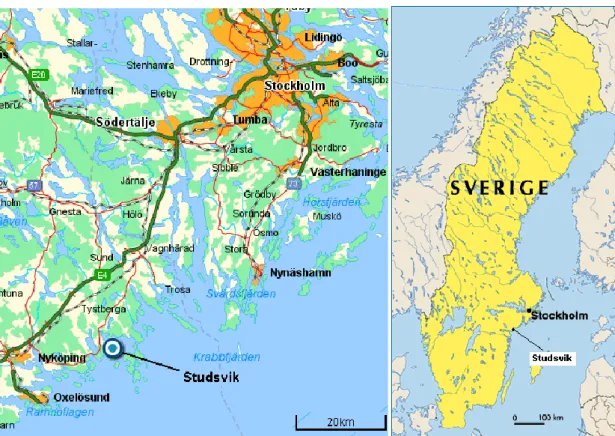
The Studsvik site is situated on the coast of the Baltic Sea in a sparsely populated area in Sweden 20 km east of the town of Nyköping and 80 km southwest of Stock-holm (Figure 1).
The site coordinates are N 58° 46’, E 17° 23’. There are several facilities for mate-rial investigation and radioactive waste treatment and storage at the site. A small number of other companies are located at the site and in its immediate surround-ings. An overview of the site is given in Appendix 1.
Figure 1. Studsvik’s geographical location.
The reactor facility is situated on moraine, sand and gravel on a bedrock of sedi-mentary vein gneiss. The area is seismically stable and there is no risk of damage to the facility due to earthquakes. The near surroundings include nature reserves as well as Natura 2000 areas. The archipelago is of high ecological value. The area is popular in terms of outdoor recreation [7].
7
The surroundings are sparsely populated. A small residential area lies immediately south of the site. Three other residential buildings are situated at a distance of 1.5 kilometres.
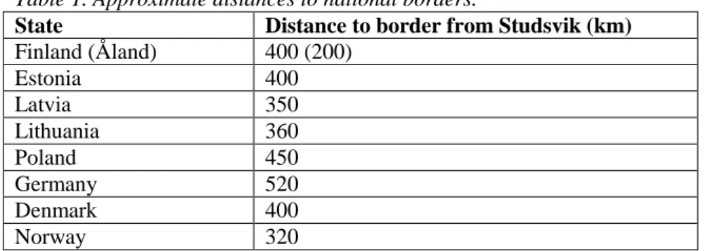
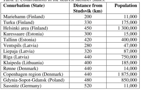
Neighbouring Member States are shown in Figure 2. Distances to national borders are given in Table 1. The closest conurbations in the nearest Member States are listed in Table 2. The nearest population centre in another Member State is Marie-hamn, situated on the island of Åland, Finland, about 200 km northeast of Studsvik.
Figure 2. Neighbouring Member States.
Table 1. Approximate distances to national borders.
State Distance to border from Studsvik (km) Finland (Åland) 400 (200) Estonia 400 Latvia 350 Lithuania 360 Poland 450 Germany 520 Denmark 400 Norway 320 SSM 2012:31
Table 2. Conurbations in the nearest Member States. Conurbation (State) Distance from
Studsvik (km)
Population
Mariehamn (Finland) 200 11,000
Turku (Finland) 330 175,000
Helsinki area (Finland) 450 1 300,000
Kuressaare (Estonia) 300 15,000 Tallinn (Estonia) 420 400,000 Ventspils (Latvia) 280 47,000 Liepaja (Latvia) 320 87,000 Riga (Latvia) 440 750,000 Klaipeda (Lithuania) 400 185,000 Rønne (Denmark) 440 14,000
Copenhagen region (Denmark) 440 1 875,000 Gdynia-Sopot-Gdansk (Poland) 480 850,000
Sassnitz (Germany) 520 11,000
1.2 Hydrology
The site is drained eastwards through small ditches to the bay, Tvären, which is part of the Baltic Sea. See Figure 3. Average drainage is 0.20 m3/(m2year).
9
Tvären (area 18 km2, average depth in the northernmost part 12 metres, overall deepest point 80 metres) is to some extent separated from the open sea by thresh-olds with no greater depth than 10 metres. The water turnover in the upper layers of Tvären (depth less than 10 metres) is 20 million m3/day [8].
1.3 Meteorology
Winds from the southwest and west predominate the area. In the winter, northwest winds are quite common as well (December to February). Average wind speed is about 7 m/s at 15 metre height. Wind speeds are somewhat higher in the autumn and in the winter. Average precipitation is 650 mm/y, average intensity is 0.5 mm/h. Average temperature during the growth period is 12°C [7, 8]. More details on weather conditions are given in Appendices 3 and 4.
1.4 Natural resources and foodstuffs
Studsvik is situated in a sparsely populated area. A few small farms are located within a few kilometres. Cereals are grown west of the site. Cattle for meat produc-tion are kept on nearby pastures. The nearest dairy farm is situated about 10 km to the north/northeast. The growth period lasts about 180 days. Commercial fishing takes place to a small extent in Tvären bay and the near surroundings in the Baltic Sea. Angling is a growing leisure pursuit.
Fresh water is produced by purifying water from Trobbofjärden, a lake. The capaci-ty of the water treatment plant is 20 m3/h [9].
Studsvik is situated in the municipality of Nyköping in the County of Söderman-land. Farmers in Södermanland grow approximately 4% of the crops produced in Sweden and own 6% of all livestock in the country. For Nyköping municipality, the corresponding data is 1% of the crops and 0.5% of the livestock, respectively. Local production near Studsvik is lower.
About 60% of all the agricultural production exported from Sweden ends up in other EU Member States, mostly Denmark, Finland, Germany, France and Poland. Estimations on the municipality of Nyköping’s share of Swedish exports of crops and livestock are given in Appendix 5.
2. The installation
2.1 Brief description and history of the
installa-tion
The nuclear research facility was built in the late 1950s and was completed in 1960. The nuclear research and material test reactors R2 and R2-0 are situated in a com-mon reactor pool. R2 is a tank type reactor and R2-0 is a mobile pool reactor. The R2 had a thermal power of 50 MW and the thermal power of R2-0 was 1 MW. The R2 reactor was used for fuel testing, studies of corrosion, radiography and produc-tion of radioisotopes, semi-conducting materials and neutrons used in basic re-search. The R2-0 reactor was used as a neutron source for treatment of patients with brain tumours (Boron Neutron Capture Therapy) and for educational purposes. The reactors were shut down in June 2005 following a decision by the operator [1, 7]. The reactor building is located approximately 100 metres from the shore. The floor of the reactor hall is 15.7 metres above sea level. The liquid waste treatment facility has been built on a slightly lower level to assure a falling gradient.
The two reactors R2 and R2-0, like many of the supporting systems, are situated inside the reactor building. Pumps, heat exchangers, storage tanks, fan systems, etc. are situated inside an adjacent pump station. The fan system is connected to a sepa-rate 85 metre stack. There are also buildings for service, a laboratory, experiments and other supporting activities. See Appendix 2.
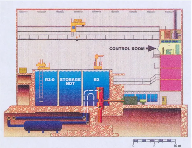
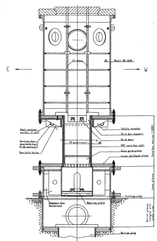
There is a water-filled reactor pool inside the reactor hall where both R2 and R2-0 are located. See Figures 4 and 5.
The main radioactive parts of the facility are the reactor structures and the primary systems. The activity of the reactor structures has been estimated by calculations and will be verified during dismantling. The degree of radioactive contamination of the systems has so far mainly been investigated by means of dose-rate measure-ments. Initial characterization using smear samples has been made of contamination on operational waste and (mainly) outer surfaces of systems. Preliminary results show different nuclide distributions in different samples, without any systematic change between different sample positions. However, according to estimations by the operator, most of the radioactive waste that will be produced will be low-level (<2 mSv/h).
11
Figure 4. Cross-section of the reactor hall with the two reactors R2 and R2-0.
13
2.2 Ventilation systems and the treatment of
gaseous and airborne wastes
The ventilation systems of the facility direct the air flows towards premises with higher risk of airborne activity. Ventilation systems in areas where there is risk of airborne activity are called ‘active systems’. The active systems evacuate four dif-ferent areas: the basement, the ‘pipe gallery’, the ion exchanger room and the emer-gency evacuation system. The air from each area is collected into a ventilation channel (flue) where it passes filters for aerosols. The four flues lead the air to the top of the 85 metre high stack, where the air is released. In each flue, the air flow is provided by a fan that has a reserve fan as backup. The system includes automatic start of each reserve fan and a prioritised power supply to ensure correct pressure distribution in the premises should the normal power supply fail.
Roof fans evacuate the air in the reactor hall. There is also a possibility to ventilate the reactor hall through the emergency evacuation system. The emergency ventila-tion system contains an iodine scrubber, which was designed to reduce the release of iodine in case of an accident during reactor operations. Although there will be no potential for releases of iodine during dismantling, the iodine scrubber will be in function during dismantling for filtration of air in connection with certain dismant-ling activities in the reactor hall.
2.3 Liquid waste treatment
Liquid wastewater arising during dismantling will be managed in an adjacent facili-ty for treatment of intermediate-level waste. Wastes will be transported in pipes in an underground culvert. The culvert system is presently used by other facilities at the site and will remain in operation throughout the dismantling of the reactor facili-ty.
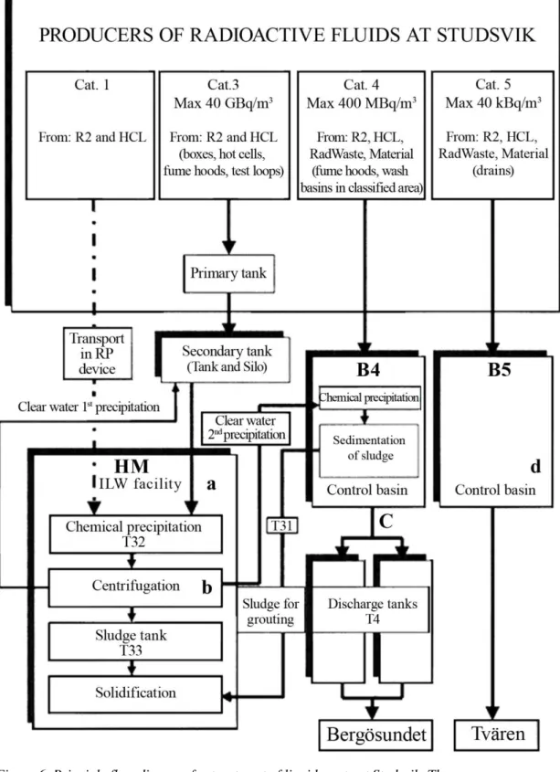
An overview of the process is provided in Figure 6. The liquid waste will be treated by precipitation and centrifugation. The remaining water phase will be treated by precipitation and sedimentation. Organic compounds that may be present in liquid waste from system decontamination will be broken down by UV oxidation [10]. Sludge from the process will be solidified by mixing it with cement in drums. Liquid waste with higher activity concentration than accepted in the culvert system can be transported in radiation protective flasks to the facility for treatment of in-termediate-level waste for immobilization. It is not expected that such liquids will arise during the dismantling work.
After analysis, the wastewater from the facility for treatment of intermediate-level waste is discharged into the sound Bergösundet. Water from controlled areas ex-pected to be free from radionuclides is checked for activity content before being discharged into Tvären bay.
Figure 6. Principle flow diagram for treatment of liquid waste at Studsvik. The letters indicate where samples are normally taken from the process: arrival (a), clear water (b) and before discharge (c and d).
15
2.4 Solid waste treatment
All solid wastes will be treated and stored at Studsvik awaiting final disposal. A brief description is given in this section. Processing and packaging are described in more detail in Section 5.2 below.
Low-level scrap metal will be transferred to the melting facility at Studsvik, operat-ed by Studsvik Nuclear AB. Low-level combustible waste will be transferroperat-ed to the incineration facility at Studsvik, operated by Studsvik Nuclear AB. Low-level, non-combustible waste will be conditioned and stored at Studsvik awaiting final dispos-al. All low-level solid waste is planned to be disposed of in the planned repository for radioactive decommissioning waste (SFR-3, see Section 5.5).
Low and intermediate-level long-lived solid waste will be transferred to the facility for treatment of intermediate-level waste in Studsvik, operated by AB SVAFO. The waste is planned to be deposited in the planned repository for long-lived waste (SFL, see Section 5.5).
The facilities mentioned above have all been licensed according to the Environmen-tal Code and the Act on Nuclear Activities [1].
2.5 Containment
The reactors are enclosed in a concrete containment. The containment is not com-pletely gas-proof, but the ventilation system guarantees underpressure (see Section 2.2 above).
3. Release of airborne
radio-active effluents in normal
conditions
3.1 Authorisation procedure in force
3.1.1 The Environmental Code
In January 2006, the former operator Studsvik Nuclear AB applied at the Environ-mental Court of Stockholm for a licence according to the EnvironEnviron-mental Code for dismantling the R2 facility. The Court referred the application to – among others – the Swedish Nuclear Power Inspectorate, the Swedish Radiation Protection Au-thority, the County Administrative Board of Södermanland and the Municipality of Nyköping.
This licence was issued on 16 March 2007. The Environmental Court did not im-pose any conditions concerning radioactive effluents. Instead, the Court referred to the Radiation Protection Act and the Act on Nuclear Activities and related regula-tions, see below.
In the licence it is stated that decommissioning shall be carried out in accordance with the schedule for the ‘main alternative’; i.e. decommissioning is to be complet-ed by the end of 2016 [3]. Due to delays in the decommissioning licensing process and to priority given to other SVAFO projects, AB SVAFO currently investigates the possibilities for an extension of this time limit.
3.1.2 Legislation on Radiation Protection
Release of radioactive substances from nuclear facilities to the environment is regu-lated by the Swedish Radiation Safety Authority’s Regulations (SSMFS 2008:23) on Protection of Human Health and the Environment from Releases of Radioactive Substances from Certain Nuclear Facilities. According to the regulations, the best available technique shall be applied to reduce such releases. Effective doses to the critical group due to the releases in one year shall not exceed 0.1 mSv (integrated over a period of 50 years).
According to the Swedish Radiation Safety Authority’s Regulations (SSMFS 2008:19) on Planning for and during Decommissioning of Nuclear Facilities, the licensee shall submit a detailed report four months before dismantling and demoli-tion of systems or construcdemoli-tion parts containing radioactive materials. The report [6] was submitted to the Swedish Radiation Protection Authority (SSI) in June 2007. This report, among other things, covers a time schedule, a review of chemical and toxic material in the facilities, induced activity, volumes and handling of radioactive waste, documentation, organisation, methods and equipment for demolition, release control and a preliminary estimate of the collective dose. Following review, SSI pointed out several areas which need to be developed further before dismantling of the reactors may take place.
17
3.1.3 Legislation on Nuclear Activities
The operator of the reactor facility holds a licence for the possession and operation of the reactors R2 and R2-0 in accordance with the Act on Nuclear Activities. The licence is also valid for decommissioning of the reactors. According to the Swedish Radiation Safety Authority’s Regulations (SSMFS 2008:1) concerning Safety in Nuclear Facilities, a decommissioning plan shall be supplemented and incorporated in the Safety Analysis Report before the dismantling of the facility may be initiated. The revised Safety Analysis Report [4, 5] was submitted to the Swedish Nuclear Power Inspectorate (SKI) in June 2007. Following review, SKI pointed out several areas which need to be developed further before the SAR can be approved.
3.2 Technical aspects
Estimations of releases of airborne radioactive effluents in normal conditions during dismantling are presented in Table 3 below [11]. The estimations were based on an analysis of the main planned dismantling activities that may cause releases to air during normal operation:
1 Emptying of the D2O system (2013)
2 Dismantling of experiment loops 1 and 2 (20132014) 3 Treatment of spent ion exchange resins (2014)
4 Other dismantling operations (2014-2017)
The D2O system contains 2,200 litres of liquid. Part of it is HTO. The system will
be drained to steel drums and the D2O will be sold. Based on experience it was
estimated that about 1 ml per barrel will be spilt, and evaporation will cause 2.9 GBq H-3 to be released into the atmosphere via the off-gas system through the main stack, see Table 3.
Dismantling of the experiment loops 1 and 2 will be performed by cutting tubes, etc. and placing them in waste containers suitable for final disposal. Based on knowledge of the activity content in the loops, it was estimated that in total about 45 kBq may be released into the atmosphere via the off-gas system through the main stack, see Table 3 (it was assumed that arrangements to prevent spread of activity will fail completely for one of the planned cutting operations).
Spent ion exchange resins from R2 will be treated at the facility for treatment of intermediate-level waste at Studsvik (see Section 2.3 above). A small amount of radionuclides might be released to air during that process, see Table 3.
During the period 2014-2017, other dismantling operations will be performed on other systems and components, which in general have less activity content than the experiment loops. For 2014, the releases to air were estimated to be 90% of the level of releases in 2013. For subsequent years, a linear decrease from the value of 2014 was assumed, due to the successive reduction of the radionuclide inventory in the facility (75% for 2015, 50% for 2016 and 25% for 2017).
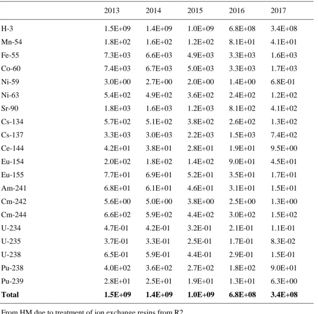
Table 3. Estimated future releases of radionuclides to the atmosphere during planned dismantling activities.
Nuclide Yearly amount released to the atmosphere (Bq) From R2 due to dismantling activities
2013 2014 2015 2016 2017
H-3 1.5E+09 1.4E+09 1.0E+09 6.8E+08 3.4E+08
Mn-54 1.8E+02 1.6E+02 1.2E+02 8.1E+01 4.1E+01
Fe-55 7.3E+03 6.6E+03 4.9E+03 3.3E+03 1.6E+03
Co-60 7.4E+03 6.7E+03 5.0E+03 3.3E+03 1.7E+03
Ni-59 3.0E+00 2.7E+00 2.0E+00 1.4E+00 6.8E-01
Ni-63 5.4E+02 4.9E+02 3.6E+02 2.4E+02 1.2E+02
Sr-90 1.8E+03 1.6E+03 1.2E+03 8.1E+02 4.1E+02
Cs-134 5.7E+02 5.1E+02 3.8E+02 2.6E+02 1.3E+02
Cs-137 3.3E+03 3.0E+03 2.2E+03 1.5E+03 7.4E+02
Ce-144 4.2E+01 3.8E+01 2.8E+01 1.9E+01 9.5E+00
Eu-154 2.0E+02 1.8E+02 1.4E+02 9.0E+01 4.5E+01
Eu-155 7.7E+01 6.9E+01 5.2E+01 3.5E+01 1.7E+01
Am-241 6.8E+01 6.1E+01 4.6E+01 3.1E+01 1.5E+01
Cm-242 5.6E+00 5.0E+00 3.8E+00 2.5E+00 1.3E+00
Cm-244 6.6E+02 5.9E+02 4.4E+02 3.0E+02 1.5E+02
U-234 4.7E-01 4.2E-01 3.2E-01 2.1E-01 1.1E-01
U-235 3.7E-01 3.3E-01 2.5E-01 1.7E-01 8.3E-02
U-238 6.5E-01 5.9E-01 4.4E-01 2.9E-01 1.5E-01
Pu-238 4.0E+02 3.6E+02 2.7E+02 1.8E+02 9.0E+01
Pu-239 2.8E+01 2.5E+01 1.9E+01 1.3E+01 6.3E+00
Total 1.5E+09 1.4E+09 1.0E+09 6.8E+08 3.4E+08
From HM due to treatment of ion exchange resins from R2
Total alpha 20 20 0 0 0
3.3 Monitoring of discharges
Monitoring of discharges during dismantling activities will continue in almost the same way as during operation. (Since the nuclear fuel has been removed from the facility, noble gases are no longer analyzed by periodic sampling in the stack).
19
Airborne discharges from the stack are continuously supervised by β- and γ-monitors. A sample (1/1000 of the evacuated volume from each of the four flues) is sucked through a mixing chamber to a measuring chamber where the monitors are installed.
Monitoring of aerosols is carried out by sampling in combined aerosol and charcoal filters that are connected to the flues in the stack. The filters are replaced and ana-lysed once a week. Analyses are made for total alpha activity (detection limit 5E-3 Bq) and by gamma spectrometry (detection limit 5 Bq for Co-60 and Cs-137). If the released alpha activity exceeds 100 Bq per week, alpha spectrometry is performed. The charcoal filters are analyzed for I-131.
Airborne activity in the exhaust air from the reactor hall is monitored in connection with the roof fans by equipment for aerosol sampling on paper filters and measure-ment of total alpha, beta and gamma activity (Edgar equipmeasure-ment, alarm levels 0.02 Bq/m3 for alpha, 70 Bq/m3 for beta and 25 microGy/h for gamma).
The occurrence of airborne tritium is supervised through continuous monitoring by ion chamber detectors in several places at the facility (alarm level 1.25 MBq/m3).
3.4 Evaluation of transfer to man
3.4.1 Models and parameter values
Calculations of local dose commitment to the theoretically most exposed individu-als use factors calculated beforehand based on unit releases of about 150 nuclides for releases to air, and about 80 nuclides for releases to water [8]. Measured nu-clide-specific releases are summed up for each facility and year. The resulting dose contributions are computed by multiplying with the factors.
The factors are calculated for different categories of recipient (air and water), point of release and age group for hypothetical individuals in the critical group.
For releases to air, estimates of factors were made using a Gaussian plume model and actual distributions of wind speed and atmospheric stability in 36 wind sectors for the site. This yielded the annual average of concentration in air in points of a 50 × 50 km2 grid around the site. Deposition on the ground was also calculated. Dose factors due to external exposure from the plume and the ground, and the internal dose factor due to inhalation were estimated based on the maximum concentration and deposition at residential areas. Turnover in terrestrial food chains was mod-elled. Representative entry points to each exposure pathway for concentration and deposition were chosen based on the maximum concentration or deposition in the area.
The public’s living habits were predefined as conservative. The hypothetical indi-viduals in the age groups were assumed to stay near the site throughout the entire year, some of the time indoors. Inhalation data was taken from ICRP 23. The hypo-thetical local inhabitants were presumed to consume locally produced crops and beef, vegetables, berries and fruit from their own gardens, fish and game from the vicinity as well as mushrooms and berries from local forests. Drinking water was assumed to be taken from a nearby lake. Yearly intake of water and foodstuffs was based on Swedish consumption statistics for different age groups.
A dilution factor of 600,000 for releases to air, as determined in Section 6.3 below, was applied to compute the contribution to the closest most exposed hypothetical individual living in another Member State (Mariehamn in Åland, Finland). The same living habits as for hypothetical local inhabitants were assumed.
3.4.2 Estimated exposure levels in other Member States
The closest conurbation in another Member State is Mariehamn on the island of Åland in Finland (cf. Table 2). The computed contribution to dose commitment for the most exposed hypothetical individual due to estimated releases to air from the R2 facility is given in Table 4.
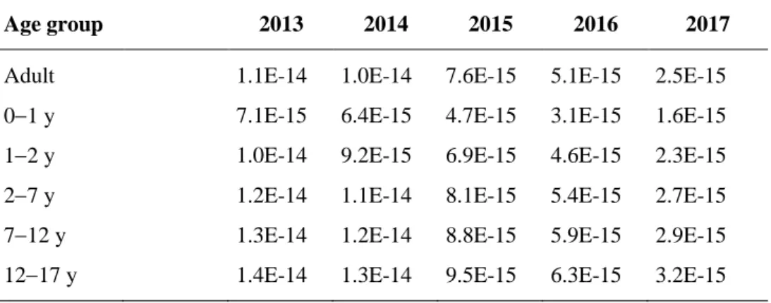
Table 4. Computed dose commitment (mSv) for a most exposed hypothetical indi-vidual in Mariehamn, Finland due to estimated releases of radionuclides to air during decommissioning of the R2 facility.
Age group 2013 2014 2015 2016 2017
Adult 1.1E-14 1.0E-14 7.6E-15 5.1E-15 2.5E-15 01 y 7.1E-15 6.4E-15 4.7E-15 3.1E-15 1.6E-15 12 y 1.0E-14 9.2E-15 6.9E-15 4.6E-15 2.3E-15 27 y 1.2E-14 1.1E-14 8.1E-15 5.4E-15 2.7E-15 712 y 1.3E-14 1.2E-14 8.8E-15 5.9E-15 2.9E-15 1217 y 1.4E-14 1.3E-14 9.5E-15 6.3E-15 3.2E-15
21
4. Release of liquid
radioac-tive effluents under normal
conditions
4.1 Authorisation procedure in force
See Section 3.1 for a general description of legislation and authorisation procedures. The Environmental Court has not stated any conditions concerning radioactive ef-fluents for the licence according to the Environmental Code. Instead, the court re-fers to the Radiation Protection Act, the Act on Nuclear Activities and related regu-lations [3].
4.2 Technical aspects
Liquid wastes arising during dismantling will be treated in the facility for treatment of intermediate-level waste at Studsvik (see Section 2.3 above).
An estimation of future releases of radionuclides to water during planned disman-tling activities is given in Table 5 [11]. The estimation is based on the actual releas-es that took place in 2008, when the sling tubreleas-es were decontaminated and about 300 m3 of liquid waste was generated and treated in the facility for treatment of intermediate-level waste. The yearly amount of liquid waste generated during future dismantling and decontamination activities is not expected to exceed this amount, except for the emptying of the reactor pools, which contain about 500 m3 of water. Since it has not been decided when the pools shall be emptied, this additional amount of liquid waste is assumed to contribute to the releases evenly distributed during the period 2010-2015 (only contributing significantly to the estimated re-lease of H-3, cf. Table 13, where the activity content of the pool water is shown). As for airborne releases, the liquid releases into air in 2012 were estimated at 90% of the liquid releases taking place in 2011. For subsequent years, a linear decrease from the value for 2012 was assumed due to the foreseen successive reduction of the radionuclide inventory in the facility (75% for 2013, 50% for 2014 and 25% for 2015).
It should be noted that the estimation is based on the conservative assumption that all of the liquid releases from the Studsvik site in 2008 can be attributed to the de-contamination of the sling tubes in the R2 facility.
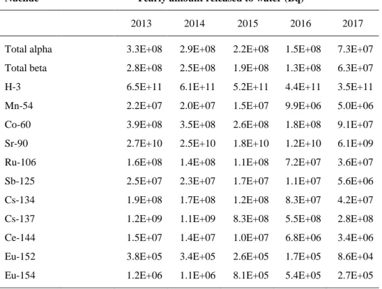
Table 5. Estimated future releases of radionuclides to water during planned dis-mantling activities.
Nuclide Yearly amount released to water (Bq)
2013 2014 2015 2016 2017
Total alpha 3.3E+08 2.9E+08 2.2E+08 1.5E+08 7.3E+07
Total beta 2.8E+08 2.5E+08 1.9E+08 1.3E+08 6.3E+07
H-3 6.5E+11 6.1E+11 5.2E+11 4.4E+11 3.5E+11
Mn-54 2.2E+07 2.0E+07 1.5E+07 9.9E+06 5.0E+06
Co-60 3.9E+08 3.5E+08 2.6E+08 1.8E+08 9.1E+07
Sr-90 2.7E+10 2.5E+10 1.8E+10 1.2E+10 6.1E+09
Ru-106 1.6E+08 1.4E+08 1.1E+08 7.2E+07 3.6E+07
Sb-125 2.5E+07 2.3E+07 1.7E+07 1.1E+07 5.6E+06
Cs-134 1.9E+08 1.7E+08 1.2E+08 8.3E+07 4.2E+07
Cs-137 1.2E+09 1.1E+09 8.3E+08 5.5E+08 2.8E+08
Ce-144 1.5E+07 1.4E+07 1.0E+07 6.8E+06 3.4E+06
Eu-152 3.8E+05 3.4E+05 2.6E+05 1.7E+05 8.6E+04
Eu-154 1.2E+06 1.1E+06 8.1E+05 5.4E+05 2.7E+05
4.3 Monitoring of discharges
In normal conditions, the liquid radioactive effluents are treated in the facilities for treatment of intermediate-level waste at Studsvik (see Section 2.3). After treatment, the water is transferred to discharge tank T4 (see Figure 6) and sampling is made for activity control. A sample of 5 litres is taken from every 130-140 m3 that are transferred to the discharge tanks. A subsample (3 ml) is analyzed for total alpha and total beta activity before release to the recipient. From all samples taken during one month, a common, weighted sample is formed, which is then analyzed for total alpha activity (detection limit 0.002 Bq/ml), gamma-emitting nuclides (detection limit 0.005 Bq/ml for Co-60 and Cs-137) and tritium (detection limit 5 Bq/ml). Samples collected during every six month period are analyzed for Sr-90 and by using alpha spectrometry. The releases from the B5 control basin (see Figure 6) are monitored according to the same methodology.
4.4 Evaluation of transfer to man
4.4.1 Models and parameter values
Radionuclides are released to water at two points, the bay, Tvären, and the sound, Bergösundet, the latter of which has a higher turnover of water (cf. Figure 6 above). To enable a conservative calculation of the consequences, all of the released nu-clides were postulated to be released to Tvären. The water turnover time of the bay has been measured at ten days. The transfer between radionuclides in water and suspended particulates as well as the transfer to fish was modelled, as was the sedi-mentation process. The ensuing concentration in fish yielded dose calculation
fac-23
tors. Also, committed dose contribution due to the general public’s presence at local beaches was computed [8].
The public’s living habits were predefined as conservative. The hypothetical indi-viduals in the age groups were assumed to be present near the site throughout the entire year, some of this time indoors. The hypothetical local inhabitants were pre-sumed to consume fish from the sea. Drinking water was aspre-sumed to be taken from a nearby lake. The yearly intake of fish was based on Swedish consumption statis-tics for different age groups.
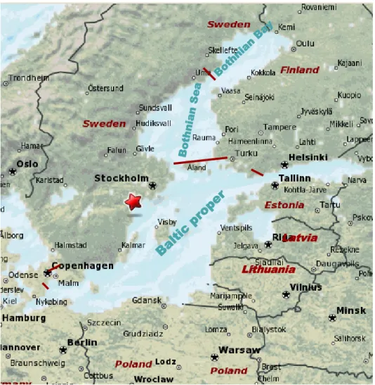
The coast of the Baltic Proper is shared by several Member States: Finland, Estonia, Latvia, Lithuania, Poland, Germany, Denmark, and also Sweden, where the
Studsvik site is located. The Baltic Sea consists of a series of sub-basins, i.e. the Bothnian Bay, the Bothnian Sea and the Baltic Proper, which are mostly separated by shallow sills, see Figure 8. Each of these basins has its own water turnover char-acteristics. Water exchange in the Baltic Sea varies, but on average, the currents of the Baltic Proper’s surface water move counter-clockwise owing to the Coriolis force.
Figure 8. The Baltic Sea, the Studsvik site (red star) and surrounding Member States. Latvia Lithuania
Ba
ltic p
ro
pe
r
Bo thn ian Se a Bo thnia n Ba y Latvia LithuaniaBa
ltic p
ro
pe
r
Bo thn ian Se a Bo thnia n Ba y Åland SSM 2012:31In order to assess the radiological consequences for members of the public in other Member States, it is assumed that the hypothetical individuals have the same way of living and the same habits as the most exposed hypothetical individual in the vicini-ty of Studsvik [11]. Since releases from Studsvik take place in brackish water, it is also assumed that the only relevant exposure pathway is the consumption of fish. Accordingly, the calculations of the local dose factor for to the theoretically most exposed individual at the Studsvik site can be used as a starting point. This local dose factor was developed and calculated by using a box model, which modelled dispersion due to mixing and the accumulation of radionuclides in the brackish water ecosystem adjacent to Studsvik.
The local dose factors for Studsvik were adjusted by using a dilution factor in order to assess the radiological consequences for members of the public in other Member States. In order to give a conservative estimate of concentrations in coastal waters adjacent to the Member States surrounding the Baltic Proper, the dilution factor was based on dilution of the water in Tvären bay into the surface water of the Baltic Proper down to a depth of 20 m. Water volumes used for the derivation of this dilu-tion factor are presented in Table 6.
Table 6. Water volumes of Tvären bay at Studsvik and of surface water (depth 20 m) in the Baltic Proper, and the ensuing dilution factor.
Tvären bay (Studsvik), volume (m3) 4.0E+08 Baltic Proper (surface water < 20 m), volume (m3) 4.6E+12
Dilution factor (-) 8.8E-05
4.4.2 Estimated exposure levels in other Member States
The computed contributions to dose commitment for individuals in other Member States, living near the Baltic Proper, are shown in Table 7.
Table 7. Future computed contributions to dose commitment (mSv) for individuals in other Member States, living near the Baltic Proper, due to releases of radionu-clides to water during decommissioning of the R2 facility.
Age group 2013 2014 2015 2016 2017
Adult 7.6E-09 6.9E-09 5.1E-09 3.4E-09 1.7E-09 01 y 4.1E-12 3.7E-12 2.8E-12 1.9E-12 9.4E-13 12 y 8.4E-09 7.5E-09 5.6E-09 3.8E-09 1.9E-09 27 y 7.6E-09 6.9E-09 5.2E-09 3.4E-09 1.7E-09 712 y 1.1E-08 1.0E-08 7.5E-09 5.0E-09 2.5E-09 1217 y 1.8E-08 1.7E-08 1.2E-08 8.3E-09 4.1E-09
25
5. Disposal of solid
radioac-tive waste
5.1 Categories of solid radioactive waste and
estimated amounts
An overview of estimated solid radioactive waste arising is shown in Table 8 below [6, 12, 13].
Table 8. Estimated amounts of different waste categories from the decommissioning of the R2 facility.
Waste category Estimated amount (tonnes)
Remark Scrap metal for direct
clear-ance (no need for special treatment foreseen)
50 For clearance levels, see Section 5.6 below Scrap metal for melting in
the Studsvik melting facility
120 Clearance of ingots after melting may take place. For clearance levels, see Section 5.6 below Low-level combustible
sec-ondary waste
50 Approximately 5 tonnes
after combustion at Studsvik
Low-level waste from dis-mantling of contaminated systems
6 For disposal in SFR-31
Low-level waste from demo-lition of building structures
3,300 For disposal in SFR-31 Activated reactor
compo-nents and heavily contami-nated system parts
15 For disposal in SFL2
1
Planned repository for radioactive decommissioning waste, see Section 5.5
2
Planned repository for long-lived low and intermediate-level waste, see Section 5.5
5.2 Processing and packaging
Low-level scrap metal will be transferred to the Studsvik melting facility. In the facility, cutting, decontamination by blasting and melting can be done. The result-ing result-ingots are subject to clearance and may be recycled by the steel industry. Ingots that need to decay before clearance may be stored at Studsvik. Slag and other wastes from the process, as well as scrap metal and ingots that cannot be cleared will be packed and stored at Studsvik awaiting final disposal.
Low-level combustible waste will be transferred to the incineration facility at Studsvik. The ashes from incineration will be packed in 100 litre drums and stored at Studsvik awaiting final disposal.
Low-level non-combustible waste will be packed in ISO containers and stored at Studsvik awaiting final disposal. Packing will be performed either in the reactor facility or in the incineration facility at Studsvik.
All low-level solid waste is planned to be disposed of in the planned repository for radioactive decommissioning waste (SFR-3, see Section 5.5).
Activated reactor components will be segmented in the reactor pool before being transferred to the facility for treatment of intermediate-level waste in Studsvik, operated by AB SVAFO. After further segmentation, the waste will be packed into 80 litre drums, which will then be placed in concrete containers with positions for five drums for further storage at Studsvik. It is possible that other containers will be used. Intermediate-level solid waste is planned to be treated in a similar way. The waste is planned to be deposited in the planned repository for low and intermediate-level long-lived waste (SFL, see Section 5.5).
5.3 Storage arrangements
All solid waste will be stored at Studsvik until the planned repositories have been taken into operation. There are several alternatives for temporary storage at the site: an underground cavern, storage buildings and containers on a hard surface outdoors. Waste due for SFL will be stored in the cavern [10].
5.4 Radiological risks to the environment,
pre-cautions taken
No significant radiological risks to the environment have been predicted due to the treatment or storage of solid radioactive waste [7].
5.5 Arrangements for the movement and
des-tinations of classified waste transferred off-site
According to present plans, radioactive waste from the decommissioning of the R2 facility will be disposed of in two different facilities being planned by the Swedish Nuclear Fuel and Waste Management Co. (SKB), see Table 9 [12].
Table 9. Estimated volumes of radioactive waste for disposal from the decommis-sioning of the reactor facility at Studsvik.
Repository Category of waste Weight
(tonnes)
Volume (m3) SFR-3 (planned) Short-lived
low and intermediate-level waste
3,300 3,700
SFL (planned) Long-lived
low and intermediate-level waste
15 28
In Sweden, SKB is responsible for the development, planning and construction of facilities for final disposal of radioactive waste from nuclear power plants. SKB is jointly owned by the Swedish nuclear power licensees. By agreement with the oper-ator, SKB is also responsible for arranging final disposal of nuclear waste from the Studsvik reactor facility.
27
SKB operates a central interim storage facility for spent nuclear fuel (Clab) and a repository for low and intermediate-level radioactive operational waste (SFR-1). In addition, SKB is planning for a repository for spent nuclear fuel, a repository for long-lived low and intermediate-level waste (SFL) and a repository for low and intermediate-level decommissioning waste (SFR-3). SFR-3 is being planned as an extension of the 1 facility with a similar design as the existing caverns in SFR-1. According to the current plans, this extension will be taken into operation in 2020. SKB also provides a system for transporting radioactive waste.
The design and location of the repository for long-lived low and intermediate-level waste (SFL) have not yet been decided. SFL is planned to be in operation in 2045. SKB’s system for transporting radioactive waste will be modernized and used for transports to SFR-3. This system includes a ship, terminal vehicles and transport containers [14].
5.6 Criteria for contaminated materials to be
released from the requirements of the Basic
Safety Standards, for disposal, recycling or
re-use
Clearance of materials is regulated by the Swedish Radiation Safety Authority’s Regulations (SSMFS 2011:2) concerning clearance of materials, rooms, buildings and land in practices involving ionising radiation [15].
According to the regulations, contaminated materials from nuclear facilities may be released from regulatory control for unrestricted use or for treatment as convention-al waste. Rooms and buildings may be released from regulatory control for contin-ued use or for demolition. The Swedish Radiation Safety Authority can also take decisions regarding clearance on a case-by-case basis following an application from the licensee. The clearance levels stated in the regulations are the same as recom-mended in European Commission Recommendations RP 122 part 1 and RP 113. The clearance of ingots from the melting facility is regulated in a separate licence. The clearance levels are identical to the recommended values in European Commis-sion recommendation RP 89, with the prerequisite that the ingots are to be delivered to another foundry where the ingots are remelted as assumed in RP 89.
5.7 Envisaged types and amounts of released
materials
5.7.1 Metal scrap
Most of the 120 tonnes of scrap metal that will be treated in the melting facility will probably be released after melting. Some years of decay storage may be necessary before clearance. The envisaged amount of scrap metal that can be released without melting or decay storage is 50 tonnes [1].
5.7.2 Waste for disposal on municipal dump sites or reuse as
filling material
The amount of building rubble and other waste from conventional demolition of the facility after clearance is estimated to be in the order of 30,000 tonnes [12]. Most of the building rubble can be used to refill the basements of the demolished facility.
29
6. Unplanned releases of
ra-dioactive effluents
6.1 Review of accidents of internal and
exter-nal origin which could result in unplanned
re-leases of radioactive substances
It is the responsibility of the licence holder to identify and analyse relevant acci-dents. A rough analysis has been presented by Studsvik Nuclear AB in the authori-zation process in accordance with the Environmental Code, see Table 11. More detailed analyses will be performed by the licensee during decommissioning as part of the planning for each sub-project.
The following accidents should be analyzed for each sub-project:
Uncontrolled spread of activity within the facility (loss of containment due to rupture, fire, flooding, etc),
Uncontrolled release of activity to the environment (failure of containment or monitoring system),
Unplanned exposure of personnel (internal or external), and Unauthorized handling of radioactive materials.
The Safety Analysis Report for the facility must include an analysis of the capacity of barriers and systems for deep defence to prevent radiological accidents and to mitigate consequences. Such analysis must be based on a systematic review of events, sequences and circumstances that can lead to a radiological accident. Table 11. Considered accidents with possible radiological impact to the environ-ment during decommissioning of the reactor facility at Studsvik.
Accident Phase Probability Consequences
to life and health
Consequences to the environ-ment
Fire in electrical cable Dismantling 1 and 2
Very low (less than once in 100 years)
No personal injuries
No damage
Fire in connection with cutting activities
Dismantling 2 Very low (less than once in 100 years) Minor personal injuries No damage Leakage of radioac-tive wastewater Dismantling 1 Low (once in 10-100 years) No personal injuries No damage Effluence of airborne activity when opening systems
Dismantling 1 Very low (less than once in 100 years) No personal injuries No damage Accident at internal transport of active material Dismantling 1 Low (once in 10-100 years) No personal injuries No damage SSM 2012:31
6.2 Reference accidents taken into
considera-tion by the competent authorities for evaluating
possible radiological consequences in the
event of unplanned releases
Since spent fuel has been removed from the facility, the inventory of radioactive substances has been reduced significantly. The remaining inventory is mainly con-tained in systems connected to the reactors and can only be released to the envi-ronment after opening or rupturing of the systems. Also, there are fewer driving forces that could cause accidental activity releases to the environment.
A risk analysis performed by Studsvik Nuclear AB [11] identified a fire in remain-ing ion exchange resins as the worst case scenario as regards release of radionu-clides to air. For releases of radionuradionu-clides to water, the conservative assumption was made that all of the reactor pool water is discharged into the Baltic Sea [11]. These two scenarios were chosen as reference accidents for the estimation of possi-ble releases to the environment.
6.3 Evaluation of the radiological
consequenc-es of the reference accidents
6.3.1 Releases to the atmosphere
The accident scenario considered is a fire in the primary pump station (cf. Appendix 2), where ion exchange resins are stored in barrels on the second floor. It was as-sumed that all of the radionuclides in the resins were released. The activity content in the resins was determined by analysing samples [11]. The source term for the accident is provided in Table 12.
It was assumed that the fire would cause the roof to collapse after one hour and cause the storage barrels to release their content to the atmosphere in one hour. The release height was assumed to be 10 m.
Table 12. Source term for stipulated fire accident in the R2 facility. Nuclide Release
(Bq)
Nuclide Release (Bq)
Mn-54 4.7E+07 Cs-134 3.8E+09
Co-58 1.2E+02 Cs-137 3.8E+10
Co-60 7.9E+09 Ce-144 1.2E+09
Zn-65 1.0E+07 Am-241 5.2E+08
Ru-106 5.1E+09 Pu-238 1.1E+09
Ag-110m 5.5E+06 Pu-239 6.2E+08
Sb-124 7.6E+01 Cm-242 3.0E+05
31
A straight-line Gaussian distribution model was used to calculate the dispersion of radionuclides in the vicinity of the facility [11]. Normal weather data for Studsvik was assumed. A dry deposition velocity of 0.1 cm/s was used. No wet deposition was assumed to occur.
The results are shown in Figure 9 as total whole body dose, which is the sum of external dose from cloud, external dose from ground, integrated over 168 h (one week), and internal dose via inhalation. No shielding against external exposure was assumed.
Figure 9. Total effective whole body dose as a function of distance.
At distances from the source exceeding approximately 20 km, the plume will be even more diluted due to large-scale weather systems, i.e. fluctuations on a much greater scale than for the calculation described above. The assumption of a plume travelling in a straight line is thus no longer valid. The dose contribution will thus be much lower further away. As a very conservative approach, extrapolating the curve in Figure 9 out to Mariehamn (corresponding to a dilution factor of about 600,000) gives an approximate dose of 8·10-9 mSv to an adult.
6.3.2 Releases to water
The accident considered is a hypothetical instant release into the Baltic Sea of the total amount (490 m3) of reactor pool water, which is the largest amount of water available for short-term release. The activity content was determined by an analysis of samples of the pool water [11]. The source term for the accident is provided in Table 13. Distance (km) 10 20 30 40 50 60 70 E ffectiv e w hole body dose (m S v) 10-4 10-3 10-2 10-1 100 SSM 2012:31
Table 13. Total amount of radionuclides in the reactor pool. Nuclide Activity (Bq)
Total alpha 9.2E+05
H-3 1.6E+12
Co-60 2.4E+07
The radiological consequences for members of the public in other Member States, living near the Baltic Proper, were estimated by adjusting the local dose factors for Studsvik with the dilution factor estimated in Section 4.4.1 (cf. Table 6) [11]. The result is shown in Table 14.
Table 14. Contribution to dose commitment (mSv) for individuals in other Member States, living near the Baltic Proper, due to accidental release of all of the reactor pool contents into the Baltic Sea.
Age group Contribution to dose commitment (mSv) Adult 1.6E-11 0–1 y 1.5E-13 1–2 y 2.9E-11 2–7 y 2.6E-11 7–12 y 3.8E-11 12–17 y 2.3E-11
33
7. Emergency plans:
agree-ments with other Member
States
The operator of the reactor facility has a plan for emergency preparedness and radi-ation protection in the event of an emergency or a threat of an emergency in nuclear facilities.
The current plan describes organization, including available personnel with compe-tence in relevant areas, such as information officers, radiologists, technicians and management staff. Alarm levels, instructions and routines to activate the alarm, instructions for informing relevant authorities and evacuation plans are described. Equipment and technical facilities for radiation measurements and contamination control are available and their use is regularly exercised. Meteorological data is measured and registered continuously.
According to the Swedish Regulations on Civil Protection (SFS 2003:789) the County Administrative Board of the County of Södermanland has established an emergency preparedness plan for the Studsvik site. The plan covers organization, liaison with other authorities and the operator, where and how to measure radioac-tivity, how to handle public information, personnel and material resources available in the county and methods of decontamination.
Sweden has signed international and bilateral agreements on a national or authority level concerning early notification and subsequent information in the event of nu-clear energy accidents. The Swedish Meteorological and Hydrological Institute (SMHI), which is manned around the clock, receives notifications of accidents abroad. The Swedish Radiation Safety Authority is responsible for forwarding the information nationally, and also for sending information from Sweden in the event of an accident in the country. The most important agreements are:
Bilateral national agreements with Norway, Denmark, Finland, Germany, Russia and Ukraine on warnings of accidents
The IAEA convention EMERCON on warnings of accidents if another country might be affected by a release
The binding EU directive on early notification (ECURIE) requires that a warning must also be given if measures are adopted for protection of the domestic population
8. Environmental monitoring
Environmental monitoring in accordance with the Swedish Radiation Safety Au-thority’s Regulations (SSMFS 2008:23) on Protection of Human Health and the Environment from Releases of Radioactive Substances from Certain Nuclear Facili-ties has been performed at Studsvik since 1957, and will continue after decommis-sioning since other nuclear facilities are located at the Studsvik site. This environ-mental monitoring also includes continuous monitoring of gamma activity in the surroundings. Meteorological data is registered continuously. The results are report-ed to the Swreport-edish Radiation Safety Authority.The licensees are responsible for the analyses. To verify the results, the Swedish Radiation Safety Authority takes random samples for analysis.
The environmental monitoring programme for Studsvik summarised in Table 15 is in effect as of 1 January 2005 [16].
Table 15. Environmental monitoring programme for Studsvik.
Sample Number
of stations
Period
(S = spring, A = autumn) Terrestrial programme
Natural vegetation Moss 2 S, A
Lichen 2 A
Spruce sprouts 2 A
Cultivated vegetation Lettuce 1 July
Pasture grass 1 A
Cereals 2 A
Fruit (apple) 1 A
Berries (currants) 1 A
Animal samples Cattle 1 A
Milk 1 Every fortnight during
pasture season
Sludge 3 A
Marine programme
Water 1 Quarterly
Sediment 5 S, A
Algae Bladder wrack
(or Green algae)
5 S, A
Diatomic algae 2 Monthly ice-free period Molluscs &
arthro-pods
Sea mussel 2 A
Baltic mussel 2 A
Fish Eel or perch 2 S, A
Dab or eelpout 1 S, A
Herring 1 S
35
Every fourth year, starting in 2006, an extended programme is run in addition to the base programme, see summary in Table 16.
Table 16. Extended environmental monitoring programme for Studsvik. Extended programme (every fourth year)
Sample Number
of stations
Period
(S = spring, A = autumn)
Algae Green algae 2 S
Bladder wrack 8 S
Molluscs Radix/Theodoxus 2 S
Sea mussel 6 S
Sediment 14 S
9. References
1 Brodén, K. Teknisk beskrivning för avveckling av verksamheten vid kärnre-aktorerna R2 och R2-0 i Studsvik. Studsvik Nuclear AB 2006, Arbetsrapport N-05/251.
2 Ellmark, C. Synpunkter på artikel 37 rapport för Studsviksreaktorerna, AB SVAFO 2011, SV-11-01.
3 Stockholms Tingsrätt, avd 9, miljödomstolen. Dom 2007-03-16, Mål nr M 4268-06. Tillstånd enligt miljöbalken till nedmontering och avveckling av kärnreaktorerna R2 och R2-0 i Studsvik, Nyköpings kommun, Söderman-lands län.
4 Gustafson, L. et al. Säkerhetsredovisning för R2-reaktorn – SAR2. Studsvik Nuclear AB 2007, Arbetsrapport N(R)-02/050 Rev 2.
5 Gustafson, L. et al. Säkerhetsredovisning för reaktorn R2-0 – SAR2-0. Studsvik Nuclear AB 2007, Arbetsrapport N(R)-02/093 Rev 2.
6 Gustafson, L., Avvecklingsplan R2- respektive R2-0-reaktorerna med tillhö-rande byggnader och annex. Studsvik Nuclear AB 2007. Studsvik Report N-07/059.
7 Brodén, K. Miljökonsekvensbeskrivning för avveckling av reaktorverksam-heten i Studsvik. Studsvik Nuclear AB 2006, Arbetsrapport N-05/250. 8 Hallberg, B. et al. Dosomräkningsfaktorer för utsläpp till vatten och luft vid
normal drift av Studsviks kärntekniska anläggningar. Studsvik Eco & Safety AB 2002, Arbetsrapport ES-02/30.
9 Gräslund C. et al. Säkerhetsanalys för R2-reaktorn – SAR2. Studsvik Nu-clear AB 2003, Arbetsrapport N(R)-02/050 Rev 1.
10 Kompletteringar från Studsvik Nuclear AB i Mål M 4268-06 angående till-stånd till nedmontering och avveckling av reaktorerna R2 och R2-0 i Studsvik. Skrivelse 2006-11-16.
11 Hallberg, B et al. Answers to questions regarding report for the R2 reactor according to Article 37 Euratom, Studsvik Technical Note N-09/100 Rev. 4, with additional errata pages.
12 Ekberg, A et al. SVAFO – Kompletterande rivningsstudie för Studsviksreak-torerna. Westinghouse Atom AB 2003. SEP 03-016, rev. 0.
13 Eriksson, A. E-mail correspondence, SSM dnr 2009/1430.
14 Fud-program 2007, Program för forskning, utveckling och demonstration av metoder för hantering och slutförvaring av kärnavfall. SKB 2007.
37
15 The Swedish Radiation Safety Authority’s regulations (SSMFS 2011:2) con-cerning clearance of materials, rooms, buildings and land in practices involv-ing ionisinvolv-ing radiation.
16 Lindén, A-M, Omgivningskontroll för de kärntekniska anläggningarna, re-vision. SSI Rapport 2004:15
17 INPO, 1986. Dose assessment manual for emergency preparedness coordina-tors. INPO 86.008.
18 Jones, J.A. et al. PC COSYMA (Version 2): An accident consequence assessment package for use on a PC, EUR Report 16239, 1995.
Appendix 1
39
Appendix 2
Overview of the reactor facility
Appendix 3
Atmospheric dispersion conditions and
tem-perature inversions
Distributions of wind direction, wind speed and Pasquill class are shown in Fig-ures 3-1 to 3-3 below [11].
Figure 3-1
Measured distribution of wind directions in Studsvik (0 degrees is due North). Data from September 1996 to August 2000 (inclusive), measured onsite at 15 m height above local ground.
Studsvik
September 1996 till och med augusti 2000
Vind från (0° är norr) 0 30 60 90 120 150 180 210 240 270 300 330 360 Frek vens (%) 0 1 2 3 4 5 6 Ostlig
vind Sydligvind Västligvind
Wind from (0 deg is North)
Fr
equenc
y
(%)
Easterly
41 Figure 3-2
Studsvik. Distribution of wind speed. Measured onsite at 15 m height above local ground level. Data from September 1996 to August 2000 (inclusive). Average wind speed: 6.7 m/s.
Figure 3-3
Studsvik. Distribution of calculated Pasquill class, based on wind speed at 15 m height and temperature difference between 15 m and 90 m height above local ground level. Onsite wind and temperature were measured during the period from September 1996 to August 2000 (inclusive).
Studsvik
September 1996 till och med augusti 2000
Vindhastighet (m/s) 0 2 4 6 8 10 12 14 16 Fr ek vens (% ) 0 5 10 15 20 25 30 35 40 45 50 Medelvind: 6.7 m/s Wind speed (m/s) Fr equenc y (%) Studsvik
September 1996 till och med augusti 2000
Pasquill-klass A B C D E F Frek vens (% ) 0 10 20 30 40 50 60 70 80 90 100 Pasquill class Fr equenc y (%) SSM 2012:31
The height of temperature inversions is not measured. Statistics regarding mixing heights were presented in [18] and are assumed to be approximately valid for Studsvik, see Table 3-1.
Table 3-1 Statistics for temperature inversions. Pasquill class Average mixing height (m)
A 1,600 B 1,200 C 800 D 560 E 320 F 200