This is the published version of a paper published in Journal of Asian Electric Vehicles.
Citation for the original published paper (version of record): Aldammad, M., Ananiev, A., Kalaykov, I. (2015)
Current Collector for Heavy Vehicles on Electrified Roads: Motion Control. Journal of Asian Electric Vehicles, 13(2): 1725-1732
Access to the published version may require subscription. N.B. When citing this work, cite the original published paper.
Permanent link to this version:
Current Collector for Heavy Vehicles on Electrified Roads: Motion Control
Mohamad Aldammad 1, Anani Ananiev 2, and Ivan Kalaykov 3
1 Center for Applied Autonomous Sensor Systems, Örebro University, Sweden, mohamad.aldammad@oru.se 2 Center for Applied Autonomous Sensor Systems, Örebro University, Sweden, anani.ananiev@oru.se 3 Center for Applied Autonomous Sensor Systems, Örebro University, Sweden, ivan.kalaykov@oru.se
Abstract
We present the adopted motion control schemes of a novel current collector manipulator to be mounted beneath a heavy hybrid electric vehicle to collect electric power from road embedded power lines. We describe our ap-proach of power line detection and tracking based on an array of inductive proximity sensors. The emphasis is on the adopted motion control logic for sequential and closed loop motions to detect and track the power line respectively. We implement the sliding mode control approach for the closed loop control scheme as straightfor-ward solution given the binary nature of the inductive proximity sensors being used. The overall architecture of the entire motion control system is presented. Finally, the implementation of the entire control logic in a form of a state machine is discussed.
Keywords
current collector, electrified road, hybrid electric vehi-cle, motion control, sliding mode control
1. INTRODUCTION
The tendency to replace the fossil fuels used by vehi-cles with electrical energy nowadays is clearly identi-fied worldwide. While the solution of storing electrical energy in batteries for small vehicles seems to be rela-tively effective, large vehicles like trucks and buses require a non-realistic large amount of batteries when driving to distant destinations. Therefore, transfer-ring electricity continuously to vehicles while driving seems to be the solution [Ranch, 2010] by equipping the roads with electrical lines and the vehicles with a current collecting subsystem.
A conductive approach to collect electric power is popular since many years, mainly in city transporta-tion (trams, trolleybuses) and trains, using pantograph
to connect to an overhead catenary line. Such concept is used by the eHighway system, Figure 1, with the developed by Siemens [Siemens, 2013] intelligently controllable pantograph. Wherever there is no over-head line, it retracts automatically and the eHighway heavy goods vehicle (HGV) automatically switches to its diesel-hybrid drive system.
Alternatively to overhead lines, the conductive ap-proach can be implemented on a ground level with road-embedded power lines and an appropriate cur-rent collector mounted beneath the vehicle, like the Alstom’s APS “Alimentation Par le Sol” technology [Alstom, 2008, 2012], or Ansaldo’s STREAM concept [Siciliano et al., 2002], [AnsaldoBreda, 2009], or like the traditional underground trains (metro) power sup-ply system. The STREAM system has more complex and expensive infrastructure and the APS technology has already proven efficiency for tramways, due to the
fixed rails and “third rail” power line.
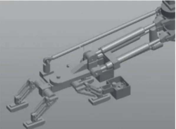
We have previously developed a prototype of a novel current collector system, Figure 2, designed for use in combination with adapted Alstom’s APS technology to road vehicles, where two conductive metal power lines are embedded into the road surface, Figure 3. This current collector system consists of a two degrees of freedom manipulator with a block of current collector shoes attached to its end-effector. Its kinematic model has been detailed in [Aldammad et al., 2014a, 2014b].
A close look at Siemens eHighway system, Figure 4, and the pantograph system mounted over trains to collect power from overhead catenary lines shows that these systems have a very wide collector shoes with respect to the line width, where shoes can slide laterally within a wide range, and therefore no precise positioning of the shoes beneath the lines is needed. On the other hand, trolleybus shoes have U-shaped profile, Figure 5, that keeps them always around the power line, while Elways system uses a groove on the road to keep the shoes always on power line, Figure 6. These types of construction do not require active control of the shoes position, provided that the vertical movements keep the shoes always around the power line or inside the grove.
In our prototype where two conductive metal power
lines are embedded into the road surface and do not provide any guiding means, therefore a continuous active control of the current collector becomes nec-essary. Contrary to the APS technology applied to tramways where the rails position is fixed with respect to the power line and consequently no sensors are needed for the power line localization, the perception, localization and tracking of the power line become a challenge in our case due to the dynamically chang-ing situation with no reference point for the vehicle, power lines and the shoes to be followed.
As the targeted heavy hybrid electric vehicles can run on both electrified and non-electrified roads, the pro-posed current collector engages only when the electri-fied road is present and the vehicle is in the state to be fed by electric power from the road. Therefore, the current collector engages or disengages according to the situation. Starting from its home position (retracted beneath the vehicle), the current collector needs to perceive and localize the power line, then move and establish the electrical connection between the shoes and the power line. Key problem in performing these actions is the perception system because it has to pro-vide continuously to the vehicle and the manipulator control system the relative coordinates of the power lines with respect to the vehicle. It has to work at very
Fig. 3 Field test of the current collector, taken from
Aldammad et al. (2014b)
Fig. 4 eHighway pantograph, taken from
Design-boom (2012)
Fig. 5 Trolleybuses’ U-shaped shoes, taken from The
Electric Tbus Group (2006)
Fig. 6 Elways groove system, taken from Elways
harsh conditions. Preferable and cheap option is to use vision-based perception, which, however, do not work properly in the presence of dust, snow, water/mud drops, or when the power lines are not well visible due to any possible reasons. That’s why in this proto-type we use inductive proximity sensors. While vision based perception installed at appropriate place on the vehicle provides measures taken from a distance, the proximity sensors have short distance sensitivity. Therefore, the only moving element, namely the ma-nipulator, has to bring the sensors along with the shoes closer to the road surface, i.e. to the power lines. In our perception solution we exploit the inherent me-tallic property of the power line by using an array of inductive proximity sensors, because there is no single sensor that can provide a signal proportional to the deviation of the shoes with respect to the lines in the above mentioned ambient conditions. The major draw-back of such sensors is their relatively short sensing distance. Therefore, the searching of the power line has to be at a level above the road surface, so-called
scanning level, where the power lines are “visible” to
sensors. When the lines are detected, the manipulator moves the end-effector down to the tracking level, where the manipulator starts to correct any lateral de-viation of the collector shoes with respect to the lines. We propose therefore a sensor array composed of two long range sensors for detecting the power line in the
scanning level and four short range sensors for
track-ing it in the tracktrack-ing level.
In this paper we present our solution of two major problems: the motion control of the manipulator to perceive and localize the power line, and the continu-ous tracking control of the power line with the collector shoes after establishing the electrical contact. In Section 2 we describe our approach of using proximity sensors for the power line detection and tracking. In Section 3 we present the control logic of the power line detection and tracking. Finally, in Section 4 we show the overall architecture of the entire motion control system.
2. POWER LINE DETECTION AND TRACKING
The major drawback of inductive proximity sensors is their relatively short sensing distance of not more than few centimeters for reasonably small and light sensors. Therefore, the searching of the power line has to be at a level above the road surface, scanning level, where the power lines are “visible” to sensors. This level should be high enough over the road to ensure a safe horizontal scanning movement of the manipulator without risking that the shoes collide with the road due to random vertical movements of the vehicle chassis. For this reason we propose a sensor array composed of two long range sensors for detecting the two “wires”
of the power line at the scanning level. Upon arrival of the manipulator vertically from home position to
scanning level, initially the manipulator moves
hori-zontally to the right limit and then starts the scanning for the power line by moving horizontally to the left. Our choice of a sensor array of two long range sensors is imposed by the power line composed of two poles that need to be detected simultaneously while scan-ning. This detection is achieved when the shoes are positioned over the line at scanning level. Upon detec-tion of the power line, the manipulator moves down vertically to tracking level, where the shoes become in contact with the power line. Our choice to continu-ously track the power line in this level is a sensor array of four short range sensors. The grey color indi-cates an activated sensor and the black color indiindi-cates a deactivated one in Figure 7, 8 and 9. It is assumed that the long range sensors 1 and 2 are already in ac-tivated state after they have detected the power line at
scanning level. Then short range sensors 3, 4, 5 and 6
respond to deviations of the shoes with respect to the conductive lines in three various ways given in details below.
2.1 Short range sensors respond when going out of the line
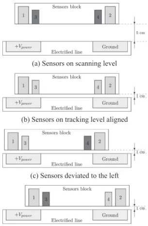
The short range sensors 3 and 4 are allocated near
(a) Sensors on scanning level
(b) Sensors on tracking level aligned
(c) Sensors deviated to the left
(d) Sensors deviated to the right
the inner edge of the conductive line qualitatively expressed on Figure 7. When the shoes are exactly po-sitioned on the line, these two sensors are ON as they stay over the metal line. If the shoes deviate slightly, but still sliding on the line, one of sensors becomes OFF to indicate left or right deviation and conse-quently activates corrective motion of manipulator. The rules to drive the manipulator depending on the perceived sensor outputs are given in a Table 1. 2.2 Short range sensors respond when coming over the line
The short range sensors 5 and 6 are allocated near the inner edge of the conductive line, but over the non-conductive area between the two power lines, quali-tatively sketched on Figure 8. When the shoes are exactly positioned on the line, these two sensors are
OFF as they face non-metallic surface. If the shoes deviate slightly, but still sliding on the line, one of sensors becomes ON to indicate left or right devia-tion and consequently activates corrective modevia-tion of manipulator. The rules to drive the manipulator in this configuration are given in Table 2.
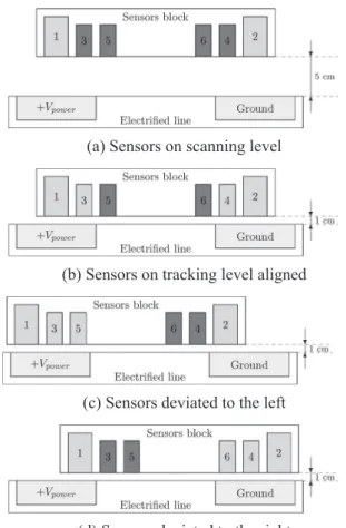
2.3 Mixed short range sensors
In this configuration, Figure 9, all short range sensors 3, 4, 5 and 6 are aligned exactly like in previous two cases. Due to this arrangement, the behavior of the two pairs (3 and 4) and (5 and 6) is following the above logic. Therefore, when the shoes deviate, two sensors (one of each pair) will respond. In contrast to the previous two configurations, this mixed configuration introduc-es a redundancy in the logic that renders the
localiza-Table 1 Action rules with sensors respond when
go-ing out of the line
S-3 S-4 Deviation Action
OFF OFF Unknown Error: line not detected ON OFF To left Move to right OFF ON To right Move to left
ON ON Null Do not move
(a) Sensors on scanning level
(b) Sensors on tracking level aligned
(c) Sensors deviated to the left
(d) Sensors deviated to the right
Fig. 8 Sensors respond when coming over the line
Table 2 Action rules with sensors respond when
com-ing over the line
S-5 S-6 Deviation Action OFF OFF Null Do not move
ON OFF To left Move to right OFF ON To right Move to left
ON ON Unknown Error
(a) Sensors on scanning level
(b) Sensors on tracking level aligned
(c) Sensors deviated to the left
(d) Sensors deviated to the right
Fig. 9 Two sensors respond when coming over the line
tion system more robust. In this case the rules to drive the manipulator are obtained by merging the previous two tables as shown in Table 3.
3. CONTROL
One can distinguish between two types of motions of the manipulator when it comes to controlling it in ex-ecuting its dedicated motions:
• A sequential motion from home position to scanning
level and then scanning to find the power line and
then establish the contact in tracking level or retract-ing to home position if the power line is not found. • A closed loop motion to track continuously the
power line after the contact has been established. • A sequential motion when retracting from tracking
level to home position.
For this reason a sequential control and closed loop control schemes are implemented for sequential and closed loop motions respectively.
As shown before in [Aldammad et al., 2014b], the motion of the manipulator is driven by two linear ac-tuators MR and ML, Figure 10. When MR contracts and
ML expands, the manipulator moves to the right, alter-natively to the left. When both MR and ML expand, the manipulator moves up, alternatively down.
The manipulator starts its dedicated motions from
home position by a strictly vertical downward motion
until the collector shoes arrive at the scanning level. This motion is achieved by contracting simultaneously both of the linear actuators MR and ML with velocities
depending on the angle α = αh that defines the angle between the manipulator’s arm and the longitudinal axis of the vehicle at home position [Aldammad et al., 2014b]. This angle is measured by an angular sensor mounted on the vertical axis of rotation of the manipulator arm. The arrival at the scanning level is detected by the mean of an ultrasound sensor that be-comes active at this predefined level above the ground and triggers consequently the controller to stop im-mediately MR and ML. Being at the scanning level the manipulator starts a strictly horizontal motion to the vehicle’s right side which is achieved by the contrac-tion of MR and the expansion of ML simultaneously with the same velocity. Arriving to the right limit, the limit switch activates and triggers the controller to reverse immediately the direction of motion, i.e. the manipulator moves to the vehicle’s left side, which is in turns achieved by the expansion of MR and the con-traction of ML simultaneously with the same velocity. The reversed motion after the activation of the right limit switch is the scanning phase of motion in which the long range proximity sensors are ready to detect the presence of the power line beneath the vehicle. If the power line is not present then the manipulator moves further to the vehicle’s left side until it reaches the left limit, where the left limit switch activates and triggers the controller to reverse immediately the di-rection of motion, i.e. the manipulator moves left to below home position, which is achieved by the con-traction of MR and the expansion of ML simultaneously with the same velocity. Upon the arrival at the below
home position defined by α = αh, the angular sensor triggers the controller to stop immediately MR and ML. From this position the manipulator goes up to home
position by a strictly vertical upward motion, which
is achieved by expanding simultaneously both linear actuators MR and ML with velocities depending on the angle α = αh.
In the case the power line is present then the long range proximity sensors switch ON when the collec-tor shoes are over the line and trigger the controller to stop immediately MR and ML. At this position a strictly vertical downward motion is initiated by contracting simultaneously both of the linear actuators MR and ML with the same velocity to bring the shoes in contact with the power line. When a reliable contact force between the shoes and the power line is achieved, the dedicated combined force sensor plus end-switch activate and trigger the controller to stop immediately the vertical motion and keep the shoes in the tracking
level.
If the power line is lost then the long range proxim-ity sensors switch OFF and trigger the controller to stop immediately MR and ML. At this position a strictly
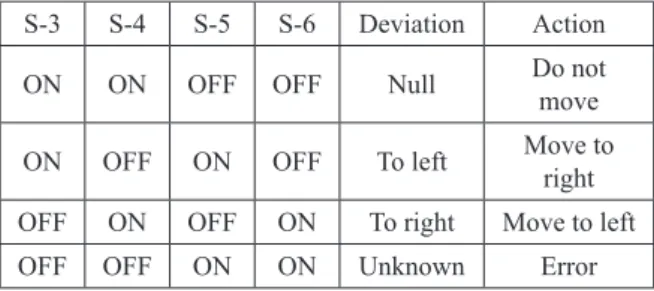
Table 3 Action rules with mixed short range sensors
S-3 S-4 S-5 S-6 Deviation Action ON ON OFF OFF Null Do not move
ON OFF ON OFF To left Move to right OFF ON OFF ON To right Move to left
OFF OFF ON ON Unknown Error
Fig. 10 Geometric model of the manipulator, taken
vertical upward motion is initiated by expanding si-multaneously both of the linear actuators MR and ML with the same velocity to bring the collector shoes back to the scanning level. The arrival at the scanning
level is detected by the mean of an ultrasound
sen-sor that becomes active at this predefined level above the ground and triggers consequently the controller to stop immediately MR and ML. Depending on the measured value of the angle α at the current position, the manipulator moves left or right to reach the below
home position defined by αh. If α > αh the manipulator moves left, otherwise, if α < αh, it moves right, given that the angle α increases from left to right. Upon the arrival at the below home position defined by α = αh, the angular sensor triggers the controller to stop im-mediately MR and ML. From this position again, the manipulator goes up to home position by a strictly vertical upward motion, which is achieved by expand-ing simultaneously both of the linear actuators MR and
ML with velocities depending on the angle α = αh. The pseudocode algorithm of the sequential control is pre-sented below.
• Pseudocode algorithm of the sequential control 1: start
2: enable actuators
3: while scanning level is not reached do
4: move down vertically
5: end while
6: stop vertical motion
7: while right limit is not reached do 8: move right horizontally 9: end while
10: stop horizontal motion
11: while power line is not detected OR left limit is not reached do
12: move left horizontally 13: end while
14: stop horizontal motion 15: if power line is detected then
16: while tracking level is not reached do
17: move down vertically
18: end while
19: stop vertical motion
20: power line tracking closed loop 21: if power line lost then
22: break loop
23: stop horizontal motion
24: while scanning level is not reached do
25: move up vertically
26: end while
27: stop vertical motion
28: while below home position is not
reached do
29: move horizontally to below
home
30: end while
31: stop horizontal motion
32: while home level is not reached do
33: move up vertically
34: end while
35: stop vertical motion
36: disable actuators
37: end if
38: else
39: while below home position is not reached do
40: move right horizontally
41: end while
42: stop horizontal motion
43: while home level is not reached do
44: move up vertically
45: end while
46: stop vertical motion 47: end if
he fact that for detecting lateral deviation of the shoes from the power line we use proximity sensors with binary ON/OFF output as the only feasible, reliable enough and available now, determined what kind of continuous control loop should be the most appropri-ate. Obviously, it should be from the class of relay-based (bang-bang) control schemes due to the used sensors. Having in mind the construction of our cur-rent collector that slides on the power line and the principle of its operation to keep always contact by compensating by a counter-action any deviation in both left-right directions, a straightforward idea is to follow the Sliding Mode Control (SMC) approach. It is well known, [Utkin et al., 2009], that the control space is separated in two parts by a zero controller output line, called a sliding line. In one part the con-troller output has positive polarity and in the other the polarity is negative. Even more, the controllers for these two parts can have different algorithms.
In our case we can consider the situation “shoes are on the power line” as corresponding to zero control-ler output line, because there is no need of correct-ing actions. Then, we can consider the left and right sides around the power line as two parts of the control space, requiring positive or negative controller output for moving the manipulator back in the “shoes are on the power line” position.
A major drawback of SMC is the bang-bang nature of the controller output, called chattering, that can shorten drastically the life of the control drive. The standard way to avoid chattering is to introduce a dead
zone around the sliding line such that the controller output is also zero, even when there is slight devia-tion. In our case such a dead zone exists naturally by placing the short-range sensors appropriately taking into account the geometry of the power line strips and the shoes. In addition certain dead zone is due to the unavoidable small backlash of the manipulator. The field tests and lab experiments proved the correctness of these considerations. The pseudocode algorithm of the closed loop control is presented below.
• Pseudocode algorithm of the closed loop control 1: loop
2: if shoes deviates to right then
3: move horizontally to left
4: else if shoes deviates to left then
5: move horizontally to right
6: else if shoes are on the line then
7: stop horizontal motion
8: end if
9: end loop
4. SYSTEM IMPLEMENTATION
The design of the manipulator was done with an im-portant requirement, namely its mass should be as small as possible, especially the mass concentrated at the end effector. Therefore, all additional equipment such as electronics, drivers and controller are installed in a separate shielded control box, attached to the vehicle chassis close to the manipulator base. This location also provides better protection from the harsh conditions and better electromagnetic compatibility. We have chosen to split our manipulator control sys-tem in two hardware blocks: the manipulator struc-ture mounted beneath the vehicle with a minimum embedded electronics, and the electronics and control
box mounted on fixed part of the vehicle carrying the controller, the DC motor drives, the data acquisition system and the power supply. The electronics and con-trol box is linked to the manipulator structure through a multiple wires cable containing all the electrical power, sensors and control lines. Figure 11 displays a schematic representation of the different hardware ele-ments of the control system.
For research and experimentation purpose we selected an integrated CompactRIO system type cRIO-9076 with a reconfigurable FPGA chassis and embedded real-time controller manufactured by National Instru-ments (NI). This chassis is equipped with two servo drive modules type NI 9514 to control the linear actuators and a 32-channel TTL digital input/output module type NI 9403 to acquire the signals from the proximity sensors. In addition we included a multi-function data acquisition (DAQ) block type NI USB-6361 also from NI for recording important test data. The manipulator contains several types of sensors: • encoders embedded in the linear actuators to measure
their elongations and enable the servo control loops; • angular sensor mounted on the vertical axis of
rota-tion of the manipulator arm to measure the angle between the manipulator’s arm and the longitudinal axis of the vehicle;
• limit switches and ultrasonic sensor to define the motion space of the manipulator;
• two triaxial accelerometers, one attached to the vehicle chassis and the other attached to the end ef-fector of the manipulator to evaluate the vibrations of the manipulator during its operation;
• two long range inductive proximity sensors for de-tecting the power line;
• four short range inductive proximity sensors for tracking the power line.
The manipulator dedicated motions have predefined limits and intermediate positions formulated by the respective limit switches and ultrasonic sensor. This largely simplifies the control system and enables the implementation of the entire control logic in a form of a state machine, which is preferable in this case, as state machines have very strict and predictable perfor-mance needed for this application.
During the development and experimental phase, we have designed a simple operator interface for moni-toring and control of the manipulator performance, Figure 12. Pushing a dedicated “start” button, the driver of the vehicle (or the operator of the tests) ac-tivates the manipulator when the vehicle approaches the electrified section on the road. The sequential con-trol is basically an ON/OFF concon-trol of the actuators
as we employ ON/OFF sensors to start/stop motions. The velocity of each actuator is fixed and maintained internally by the servo control loop. In addition, the controller checks the status of the manipulator and sends alarms to inform the driver. In the particular case when the manipulator loses the power line or when the power line ends on a given part of the road, an emergency stop is activated. It stops the horizontal tracking motion and retracts the manipulator to its
home position beneath the vehicle. The emergency
stop can also be activated by the driver by pressing an emergency switch. The signal thus generated produces a high priority interrupt in the controller which acti-vates the emergency stop routine.
Specific interface for integrating the current collector control system will be developed at the final stage of the project.
5. CONCLUSION
In this paper we have presented the main considera-tions in the control of the current collector manipula-tor. We have:
• motivated our choice to use two types of inductive proximity sensors: long range and short range sen-sors to detect and track the power line respectively; • presented three minimal configurations of inductive
proximity sensors array that have been tested and approved in real environment;
• motivated and detailed the adopted sequential con-trol and closed loop concon-trol schemes for sequential and closed loop motions respectively;
• motivated our choice in using the sliding mode control approach for the closed loop control scheme based on the binary ON/OFF output of the used proximity sensors, and resolved the chatter-ing problem of this control approach by placchatter-ing the short-range sensors appropriately to introduce a dead zone around the sliding line;
• presented the overall architecture of the entire motion
Fig. 12 Operator interface
control system and motivated the implementation of the entire control logic in a form of a state machine. Ongoing work is on dynamic analysis of the current collector for achieving improved performance and in-creased control robustness.
Acknowledgements
Authors are grateful to Volvo Trucks, Gothenburg, Sweden, whose financial support, team work and excellent field test conditions gave the possibility to materialize the proposed concepts.
References
Aldammad, M., A. Ananiev, and I. Kalaykov, Current collector for heavy vehicles on electrified roads,
Proceedings of the 14th Mechatronics Forum Inter-national Conference, Mechatronics 2014, 436-441,
2014a.
Aldammad, M., A. Ananiev, and I. Kalaykov. Current collector for heavy vehicles on electrified roads: kinematic analysis, International Journal of Electric
and Hybrid Vehicles, Vol. 6, No. 4, 277-297, 2014b.
Alstom, APS 3D animation, 2012, http://www:alstom:com/ press-centre/2010/11/APS-3D-animation.
Alstom, Wireless Trams with APS, 2008. http:// www:its:uci:edu/~jaykay/transit-documents/cate-nary-free-LRT-Alstom:pdf.
AnsaldoBreda, TramWave: Ground-Level Power
Sup-ply System, Booklet, 2009.
Designboom, eHighway electric lines to power hybrid trucks in LA, 2012, http://www:designboom:com/ technology/ehighway-electric-lines-to-powerhy-brid-trucks-in-la.
Elways, Conductive feeding of vehicle in motion, 2013, http://elways:se/?lang=en.
Ranch, P., Elektriska vägar - elektrifiering av tunga vägtransporter (förstudie), Technical report,
Gront-mij AB, 2010.
Siciliano, V., and A. Del Naja, Power line for an elec-tric vehicle, 2002. US patent 6427816.
Siemens, Electric-Powered Road Freight Traffic, 2013, http://www:mobility:siemens:com/mobility/ global/en/interurban-mobility/road-solutions/elec- tric-powered-hgv-traffic-eHighway/Pages/electric-powered-hgv-traffic-eHighway:aspx.
The Electric Tbus Group, Trolleybus Overhead, 2006, http://www:tbus:org:uk/overhead:htm.
Utkin, V., J. Guldner, and J. Shi, Sliding Mode Control
in Electro-Mechanical Systems, Second Edition,
CRC Press, 2009.