PERFORMANCE
EVALUATION OF WIMAX
Raza Akbar Syed Aqeel Raza Usman Shafique
This thesis is presented as part of Degree of
Master of Science in Electrical Engineering
Blekinge Institute of Technology March 2009
Blekinge Institute of Technology School of Engineering
Department of Telecommunication Supervisor: Dr. Doru Constantinescu Examiner: Dr. Doru Constantinescu
Dedicated to
Dedicated to
Dedicated to
The advancements in broadband and mobile communication has given many privileges to the subscribers for instance high speed data connectivity, voice and video applications in economical rates with good quality of services. WiMAX is an eminent technology that provides broadband and IP connectivity on “last mile” scenario. It offers both line of sight and non-line of sight wireless communication. Orthogonal frequency division multiple access is used by WiMAX on its physical layer. Orthogonal frequency division multiple access uses adaptive modulation technique on the physical layer of WiMAX and it uses the concept of cyclic prefix that adds additional bits at the transmitter end. The signal is transmitted through the channel and it is received at the receiver end. Then the receiver removes these additional bits in order to minimize the inter symbol interference, to improve the bit error rate and to reduce the power spectrum. In our research work, we investigated the physical layer performance on the basis of bit error rate, signal to noise ratio, power spectral density and error probability. These parameters are discussed in two different models. The first model is a simple OFDM communication model without the cyclic prefix, while the second model includes cyclic prefix.
CH A P T E R 1 ... 10
Introduction to WiMAX ... 10
1.1 History of Broadband Communication ... 10
1.2 Generations of Mobile Phone ... 10
1.3 Broadband ... 11
1.3.1 Types of Broadband... 12
1.4 WiMAX ... 17
1.4.1 Evolution of WiMAX ... 18
1.4.2 WiMAX Objectives... 19
1.5 Silent Features of WiMAX ... 25
CH A P T E R 2 ... 29
Wireless Communication ... 29
2.1 Basic Structure of Communication System... 29
2.2 Forms of Communication... 32 2.3 Transmission Impairments... 32 2.3.1 Attenuation ... 33 2.3.2 Delay Distortion ... 33 2.3.3 Noise ... 34 2.3.4 Fading... 35 2.3.5 Doppler Shift ... 36
Orthogonal Frequency Division Multiplexing ... 37
3.1 Need for OFDM... 37
3.2 Multicarrier Modulation ... 38
3.3 Basics of OFDM... 40
3.3.1 OFDM Guard Band Intervals ... 40
3.3.2 Circular Convolution and Discrete Fourier Transform (DFT)... 41
3.3.3 Cyclic Prefix... 41
3.3.4 Frequency Equalization... 42
3.3.5 Block Diagram of OFDM System ... 43
3.3.6 Synchronization & Peak to Average Ratio (PAR) ... 44
3.4 Orthogonal Frequency Division Multiple Access ... 45
3.4.1 Multiple Access Strategies ... 45
3.4.2 OFDMA Resource Allocation Technique ... 48
3.4.3 OFDMA Protocols in WiMAX... 49
3.4.4 Advantages of OFDMA... 50
CH A P T E R 4 ... 52
Modulation & Coding ... 52
4.1 Digital Modulation ... 52
4.1.1 Amplitude-Shift Keying (ASK)... 53
4.1.2 Frequency-Shift Keying (FSK) ... 54
4.4 Quadrature Amplitude Modulation ... 57
4.5 Adaptive Modulation Techniques in WiMAX ... 58
4.6 Error Correction and Coding ... 59
4.6.1 Forward Error Correction... 60
CH A P T E R 5 ... 63
Simulation ... 63
5.1 Simulation Model ... 64
5.1.1 Model – 1 (Simple Model)... 64
5.1.2 Model – 2 (Model with Cyclic Prefix) ... 65
5.2 Mersenne Twister - Random Number Generator (RNG) Algorithm ... 65
5.3 OFDM BER Simulation and Adaptive Modulation Technique ... 66
5.3.1 OFDM with Adaptive Modulation Techniques in PURE AWGN ... 66
5.3.2 Theoretical Values of BER using Adaptive Modulation Techniques in OFDM .. 68
5.3.3 OFDM with Adaptive Modulation Techniques in AWGN + Rayleigh Fading Channel with Cyclic Prefix (CP) ... 69
5.4 Probability of Error (Pe) for Adaptive Modulation... 71
5.5 Effect of SNR on OFDM system with respect to Power Spectral Density ... 73
5.6 Channel Attributes with and without CP... 75
5.6.1 Without CP... 75
5.6.2 With CP ... 76
CH A P T E R 6 ... 78
Conclusion... 78
AP P E N D I C E S... 79
Appendix-A: Matlab Code without Cyclic Prefix (Model-I) ... 79
Appendix-B: Matlab Code with Cyclic Prefix (Model-II) ... 83
Appendix-C: User Defined Function used in Code ... 87
Appendix-D: Matlab Built In Function used in Code ... 88
Appendix-E: Matlab Requirements ... 89
Figure 1: Increases in number of subscriber in millions from year 1995 to 2005... 12
Figure 2: Wireless LAN Infrastructure Mode ... 16
Figure 3: Wireless LAN Adhoc Mode ... 16
Figure 4: WiMAX Overview ... 18
Figure 5: WiMAX Objectives ... 20
Figure 6: WiMAX Network IP based Architecture ... 24
Figure 7: Elements of a communication system... 29
Figure 8: Communication system ... 30
Figure 9: Single carrier system ... 37
Figure 10: Multicarrier technique... 38
Figure 11: OFDM transmitter ... 39
Figure 12: OFDM receiver ... 40
Figure 13: OFDM guard band interval ... 41
Figure 14: OFDM cyclic prefix extension... 42
Figure 15: OFDM block diagram ... 44
Figure 16: Frequency division multiple access ... 46
Figure 17: Time division multiple access ... 47
Figure 18: Code division multiple access ... 48
Figure 19: Digital modulation... 52
Figure 20: Baseband information signal... 53
Figure 21: Binary amplitude shift keying (On-Off Keying) ... 54
Figure 22: BPSK constellation... 55
Figure 23: QPSK constellation ... 56
Figure 24: 16QAM & 64QAM constellation... 58
Figure 25: Adaptive modulation in WiMAX... 59
Figure 26: Error correcting encoder & decoder model ... 60
Figure 27: Simple ½ Rate Convolutional encoder... 61
Figure 28: ½ systematic encoder with feedback... 61
Figure 29: WiMAX convolutional encoder ... 62
Figure 30: OFDM transmitter simple model ... 64
Figure 31: OFDM transmitter model with cyclic prefix ... 65
Figure 32: OFDM with Adaptive Modulation Techniques in PURE AWGN ... 67
Figure 33: Theoretical Values of BER using Adaptive Modulation Techniques in OFDM . 68 Figure 34: OFDM with Adaptive Modulation Techniques in AWGN + Rayleigh Fading Channel with Cyclic Prefix (CP) ... 70
Figure 35: Probability of Error (Pe) for Adaptive Modulation ... 72
Figure 36: Effect of SNR level 100 on OFDM system with respect to Power Spectral Density... 74
Figure 37: Effect of SNR level -100 on OFDM system with respect to Power Spectral Density... 75
Table 1: Mobile Phone Generations ... 10
Table 2: WiMAX standards ... 22
Table 3: OFDMA protocols... 49
Table 4: QPSK signal space characterization ... 56
Table 5: Adaptive modulation in pure AWGN, SNR and bits/symbol comparison... 67
Table 6: Performance with respect to SNR and BW Utilization for pure AWGN Environment... 68
Table 7: Adaptive modulation theoretical values, SNR and bits/symbol comparison ... 69
Table 8: Performance with respect to SNR and BW Utilization for theoretical value of BER. ... 69
Table 9: OFDM in AWGN + Rayleigh Fading Channel with Cyclic Prefix (CP), SNR and bits/symbol comparison ... 70
Table 10: Performance with respect to SNR and BW Utilization for OFDM in AWGN + Rayleigh Fading Channel with Cyclic Prefix (CP). ... 71
Table 11: Probability of Error (Pe) for Adaptive Modulation, comparison SNR and bits/symbol... 72
Table 12: Performance with respect to SNR and BW Utilization for Probability of Error (Pe). ... 73
AP Access Point
AAA Authentication Authorization and Accounting ADSL Asymmetrical Digital Subscriber
AES Advanced Encryption Standard AMC Adaptive modulation and coding AMPS Advanced Mobile Phone System ASN-GW Access Service Network Gateway ASN Access Service Network
ASK Amplitude-Shift Keying
AWGN Additive White Gaussian Noise BER Bit Error Rate
BPL Broadband over Power Line BPSK Bi-Phase Shift Keying BLER Block Error Rate BS Base Station BSS Basic Service Set
CC Convolutional Encoder CDMA Code Division Multiple Access CPE Customer Premise Equipment CSN Connectivity Service Network DES Data Encryption Standard DFT Discrete Fourier Transform dB Decibel
DSL Digital Subscriber Line Eb/No Energy per Bit to Noise Ratio EDGE Enhanced Data GSM Environment
ETSI European Telecommunication Standard Institute FDMA Frequency Division Multiple Access
FFT Fast Fourier Transform FSK Frequency-Shift Keying
GSM Global system of mobile communication GPRS General Packet Radio Service
HDSL High data rate Digital Subscriber Line Hz Hertz or Cycles per Second
IBSS Independent Basic Service Set ICI Inter Carrier Interference
IEEE Institute of Electric and Electronic Engineers IFFT Inverse Fast Fourier Transform
ISI Inter Symbol Interference
ITU International Telecommunication Union LAN Local Area Network
LOS Line of Sight
MAN Metropolitan Area Network Mbps Megabits per Second
MIMO Multiple Input, Multiple Output MS Mobile Station
MSR maximum Sum Rate NIC Network Interface Card NLOS Non or Near Line of Sight
OFDM Orthogonal Frequency Division Multiplexing OFDMA Orthogonal Frequency Division Multiple Access PAPR Peak to Average Power Ratio
PAR Peak to Average Ratio
PDSL Power Digital Subscriber Line PHY Physical Layer
PM Phase Modulation
PRC Proportional Rate Constraints PSK Phase-Shift Keying
PSTN Public switch telephone Network PTP Point-to-Point
QAM Quadrature Amplitude Modulation QoS Quality of Service
QPSK Quadrature Phase Shift Keying RF Radio Frequency
SC Single Carrier
SDSL Symmetrical Digital Subscriber Line SINR Signal to Interference and Noise Ratio SISO Soft in Soft out
SNR Signal-to-Noise Ratio TDD Time Division Duplex TDM Time Division Multiplexing TDMA Time Division Multiple Access
UMTS Universal Mobile Telecommunication System UWB Ultra Wideband
VDSL Very high data rate Digital Subscriber Line VoIP Voice over Internet Protocol
VoD Video on Demand
WiMAX Worldwide Interoperability for Microwave Access W-CDMA Wideband Code Division Multiple Access
Introduction to WiMAX
1.1 History of Broadband CommunicationMarconi presented the idea of wireless communication in 1895. Today it is used in satellite transmission, broadcasting of radio and television channels and cellular networks. There has been tremendous advancement in the transmission and reception of voice and data through wireless communication.
1.2 Generations of Mobile Phone
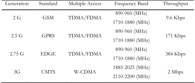
Before 1977, wireless communication was only used in military applications and for research purposes in satellite communication. The evolution of Advanced Mobile Phone System (AMPS) was the starting and turning point in wireless communication by offering a two way communication (i.e. Full Duplex Mode). It uses analogue technology and also supports data streams up to 19.2 Kbps. AMPS is an example of first generation of wireless phones. Details of other generations of mobile phone are shown in Table 1 [1, 2, 5].
Generation Standard Multiple Access Frequency Band Throughput 2 G GSM TDMA/FDMA 890-960 (MHz) 1710-1880 (MHz) 9.6 Kbps 2.5 G GPRS TDMA/FDMA 890-960 (MHz) 1710-1880 (MHz) 171 Kbps 2.75 G EDGE TDMA/FDMA 890-960 (MHz) 1710-1880 (MHz) 384 Kbps 3G UMTS W-CDMA 1885-2025 (MHz) 2110-2200 (MHz) 2 Mbps Table 1: Mobile Phone Generations
The 4th Generation of mobile phone system is under research with an objective of fully
Internet Protocol (IP) based integrated system [3]. The only difference with 3G is that it provides an IP based solution for data, voice and multimedia services to subscribers on the basis of two concepts i.e. “Anywhere” and “Anytime”. In this scenario, the users are always connected to the network with good and reliable data connectivity, where ever they go and whatever the time is. The generations that came after the 2.5th generation are also referred as
the broadband generations because these generations have high data rates and provide multimedia services to their subscribers.
1.3 Broadband
The term Broadband has no specific definition because every country has different characteristics of a broadband connection but normally broadband is defined as the high speed, reliable and on-demand internet connectivity. Broadband access not only gives the access to download files more quickly and provides faster web surfing but also enables multimedia applications like real-time audio, video streaming, multimedia conferencing and interactive gaming. The broadband connection is also used as voice telephony by using the Voice over Internet Protocol (VoIP) technology. Different organizations such as International Telecommunication Union (ITU) or other international regulators specified that if the downloading speed is in the range of 256 Kbps to 2 Mbps or higher then it fall in the category of Broadband connections. By considering these points they formed the formal definition as [4]:
“As an always-on the data connection side that is able to support various interactive services and that has the capability of a minimum download speed of 256 Kbps.”
In recent years, a remarkable growth in wireless and broadband technologies has been found and these technologies enjoyed rapid market adoption. The graph in Figure 1 indicates the growth rate of the broadband and wireless technologies throughout the world in recent years.
0 11 200 2000 0 500 1000 1500 2000 1995 2005
Increase in the No. of Subscribers in Million from year 1995 to 2005.
Broadband Wireless
Figure 1: Increases in number of subscriber in millions from year 1995 to 2005 1.3.1 Types of Broadband
We can divide the broadband technologies into fixed and wireless broadband. The fixed broadband technologies are Digital Subscriber Line (DSL), cable modem, optical fiber and Broadband over Powerlines (BPL). In the meantime, Wi-Fi and WiMAX are examples of wireless broadband communication [6].
1.3.1.1 Fixed Broadband Technologies Digital Subscriber Line (DSL):
DSL is a wired technology that is used to transmit data over traditional copper telephone lines already installed in homes and offices. DSL based broadband technology gives faster transmission speeds that ranges from several hundred bits per second (Kbps) to millions of bits per seconds (Mbps). The speed and availability of the DSL service is dependent on the distance from the home or office location to the telephone exchange that provides the service to that area. DSL can be classified as Asymmetrical Digital Subscriber Line (ADSL) and Symmetrical Digital Subscriber Line (SDSL). The residential subscribers which are using the services for internet surfing only, they require to receive lot of data. In this case, there is no need of sending much data. Hence, ADSL is an appropriate service for these types of customers. ADSL system provides more speed in downstream direction as compared to the upstream direction. The SDSL is suitable for businesses and offices that offer services like
video conferencing which require a significant amount of bandwidth in both upstream and downstream directions.
Now-a-days, other faster forms of DSL are also available, typically for large business organizations and offices. These are High data rate Digital Subscriber Line (HDSL) and Very high data rate Digital Subscriber Line (VDSL).
Cable Modem:
Cable Modem is a type of modem that provides broadband connectivity to subscribers over cable television coaxial cables. It is used to deliver sound and pictures to the subscriber’s TV set. Cable modem enables the users to connect their PC to a local cable TV line and enjoy transmission speeds of 1.5 Mbps or more. Cable modem is an external device with two connections; one for the TV cable wall outlets while the other one is for the PC.
Optical Fiber:
Fiber or Optical Fiber uses either transparent glass or plastic or a combination of these two materials. It is a newer technology that permits transmission at much higher data rates as compared to other sources of communication along long distances. This technology converts the electrical signal that carries data to a light source and sends it through transparent glass fiber. The optical fiber cable diameter is the same as the diameter of the human hair. The optical fiber connection not only provides broadband connectivity but at the same time it also delivers voice and video services such as VoIP and Video on Demand (VoD).
The optical fiber cable can be classified into single mode fiber and multi mode fiber cables. The single mode fiber is used for transmission over longer distances, while the multi mode fiber is used for shorter distances (up to 500 meter). The transmitting speed in optical fiber communication is much higher than current DSL and cable modem speed. It is typically in the range of tens or even hundreds of Mbps.
Broadband over Powerline (BPL):
It is also called Power Digital Subscriber Line (PDSL) and uses Power Line Carrier (PLC) for sending and receiving radio signals over the existing electric power distribution network [7]. The PLC modems can transmit data in medium and high frequencies, i.e., in the range of 1.6 MHz to 80 MHz electrical carriers. The modem has a speed range of 256 Kbps to 2.7 Mbps, whereas the use of repeaters speeds up the data rates to 45 Mbps.
BPL is an emerging and a new technology and so far it has been deployed in very limited areas but it is no doubt an evolving technology because power distribution networks are installed everywhere and thus this is the only technique that perfectly provides broadband facilities to every customer.
1.3.1.2 Wireless Broadband Technologies
The wireless broadband technologies are bringing the broadband experience closes to a wireless context to their subscribers by providing certain features, convenience and unique benefits. These broadband services can be categorized into two types; Fixed Wireless Broadband and Mobile Broadband. The fixed wireless broadband provides services that are similar to the services offered by the fixed line broadband. But wireless medium is used for fixed wireless broadband and that is their only difference. The mobile broadband offers broadband services with an addition namely the concept of mobility and nomadicity. The term nomadicity can be defined as “Ability to establish the connection with the network from different locations via different base stations” while mobility is “the ability to keep ongoing connections engaged and active while moving at vehicular speeds” [9]. Examples of wireless broadband technologies are Satellite communication, Wireless LAN and WiMAX.
Satellite Broadband:
Satellite Communication is also used to provide broadband services for those locations where fixed broadband infrastructure is not available and for those subscribers who live in remote areas. These days satellite broadband services are used in ships and land vehicles. Satellite Broadband has two types which are as follows [8]:
1. One Way Satellite Broadband 2. Two Way Satellite Broadband
Wireless LAN:
Wireless Local Area Network (WLAN) is a wireless technique that has replaced wired networks. It connects number of devices or computers through radio waves. WLAN gives more flexibility and provides mobility to subscribers within a campus or workplace. WLAN not only gives mobility but it also ensures provides ease of installation, affordability and scalability as compared to the wired networks [10]. The basic WLAN structure comprises an Access Point (AP) or transceivers placed on fixed locations which are connected to the wired network through ordinary LAN or Ethernet cables. The devices which have wireless Network Interface Card (NIC) communicate with AP’s for transmission and reception of data. There are two types of modes in WLAN; Infrastructure Mode and Ad-Hoc mode. Infrastructure mode is comprised on APs connected with the wired network and these APs are communicating with the devices that have Wireless NIC’s. It is also referred as Basic Service Set (BSS). In Ad-Hoc mode, devices are communicating directly with each other and they are not using any AP or any wired network. It is also termed as Peer to Peer network or Independent Basic Service Set (IBSS). The Infrastructure and Ad-Hoc networks are shown in Figure 2 & 3.
Figure 2: Wireless LAN Infrastructure Mode
The standard used by the Wireless LAN is IEEE 802.11. It uses 5 GHz and 2.4 GHz spectrum bands and can further be classified as:
• IEEE 802.11a: Uses 5 GHz frequency and 54 Mbps throughput. • IEEE 802.11b: Uses 2.4 GHz frequency and 11 Mbps throughput. • IEEE 802.11g: Uses 2.4 GHz frequencies and 54 Mbps throughput. • IEEE 802.11n: Uses 2.4 and 5 GHz frequency and 600 Mbps throughput.
1.4 WiMAX
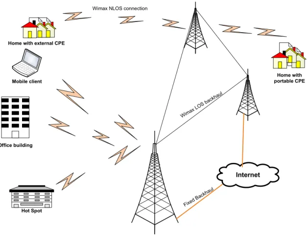
WiMAX is the abbreviation of Worldwide Interoperability for Microwave Access and is based on Wireless Metropolitan Area Networking (WMAN). The WMAN standard has been developed by the IEEE 802.16 group which is also adopted by European Telecommunication Standard Institute (ETSI) in High Performance Radio Metropolitan Area Network, i.e., the HiperMAN group. The main purpose of WiMAX is to provide broadband facilities by using wireless communication [24]. WiMAX is also known as “Last Mile” broadband wireless access technology. WiMAX gives an alternate and better solution compared to cable, DSL and Wi-Fi technologies as depicted in Figure 4.
Internet Wima x LOS back haul Home with portable CPE Wimax NLOS connection
Office building Mobile client Home with external CPE
Fixed
Bac
khau
l
Hot Spot
Figure 4: WiMAX Overview
1.4.1 Evolution of WiMAX IEEE 802.16 Working Group:
In 1998, the IEEE 802.16 working group focused to develop WMAN solution for Line of Sight (LOS) based point to point and point to multipoint wireless broadband systems. It was also decided that the frequency range for IEEE 802.16 will be 10 GHz to 66 GHz. The first standard of WiMAX was completed in December 2001 which employs single carrier physical (PHY) layer with burst Time Division Multiplexed (TDM) on MAC layer.
IEEE 802.16a:
In January 2003, the working group produced another standard, IEEE 802.16a, after some amendments in the earlier standard including Non-Line of Sight (NLOS) applications in the frequency range of 2 GHz to 11 GHz band. It uses Orthogonal Frequency Division Multiplexing (OFDM) on physical layer with Orthogonal Frequency Division Multiple Access (OFDMA) on the MAC layer.
IEEE 802.16-2004:
IEEE introduced the new standard, IEEE 802.16-2004, replacing all the previous versions. The main focus is to target fixed applications. It is also called as Fixed WiMAX or IEEE 802.16d.
IEEE 802.16e-2005:
In December 2005, IEEE approved and launched its new standard IEEE 802.16e-2005. This new standard has come after some amendments in IEEE 802.16-2004 that is the support of mobility. This system gives the concept of nomadic and mobility services to WiMAX technology. It is also referred as Mobile WiMAX.
Moreover, the WiMAX forum defines the subset of mandatory and optional physical and MAC layer features for fixed and mobile WiMAX standards and they are known as System Profile. The system profiles based on IEEE 802.16-2004, OFDM PHY, are called as fixed system profiles. The system profiles of IEEE 802.16e-2005 scalable OFDMA PHY are known as mobile system profiles. The details of operating frequencies, channel bandwidth, modulation and multiplexing techniques etc for these standards are given in Table 2 [24, 35].
1.4.2 WiMAX Objectives
Figure 5: WiMAX Objectives
Interoperability:
Main objective of WiMAX is interoperability. Based on international standards, interoperability makes it easier for users to move and use their subscriber module with different operators. All operators can select equipment from different vendors because of the standardized adoption.
Wide Coverage:
WiMAX can adopt techniques that support several modulation levels, i.e., QPSK, 16 -QAM and 64 – QAM and thus WiMAX systems are capable of covering large area.
High Capacity:
WiMAX provides higher bandwidths as compared to Global System for Mobile communication (GSM) and Universal Mobile Telecommunication System (UMTS). It uses 64-QAM modulation technique which gives channel bandwidth up to 10 MHz.
High Security:
WiMAX supports latest encryption standards like AES and Triple-DES. It encrypts the links between the base station and the subscriber module, ensuring users confidentiality, integrity, and authentication.
Flexible Architecture:
WiMAX supports several system architectures including:
• Point-to-Point • Point-to-Multipoint • Ubiquitous coverage
Quality of Service (QoS):
For ensuring QoS, WiMAX can be optimized for different types of traffic:
• VoIP
• Multimedia applications • Data
Mobility:
WiMAX version based on IEEE 802.16e standard has a main key feature which is mobility that is accomplished by introducing S-OFDMA and Multiple Input and Multiple Output (MIMO) techniques at physical layer, making it highly appropriate for the mobile environment.
Introduction to WiMAX Chapter 1 802.16a 802.16d-2004 802.16e-2005
Status Completed December 2001
Completed June 2004 Completed December 2005
Application Fixed LOS Fixed NLOS Fixed and mobile NLOS
Frequency band 10GHz-66GHz 2GHz-11GHz 2GHz-11GHz for fixed; 2GHz-6GHz for mobile Modulation QPSK, 16 QAM, 64 QAM QPSK, 16 QAM, 64 QAM QPSK, 16 QAM, 64 QAM
Gross data rate 32Mbps-134.4Mbps 1Mbps-75Mbps 1Mbps-75Mbps Multiplexing Burst TDM/TDMA Burst TDM/TDMA/OFDMA Burst TDM/TDMA/OFD MA
MAC architecture
Point-to-multipoint, mesh Point-to-multipoint, mesh Point-to-multipoint, mesh Transmission Scheme Single carrier only
Single carrier only, 256 OFDM or 2048 OFDM
Single carrier only, 256 OFDM or scalable OFDM with 128, 512, 1024, 2048 sub-carriers
Duplexing TDD and FDD TDD and FDD TDD and FDD Channel bandwidhs 20MHz, 25MHz, 28MHz 1.75MHz, 3.5MHz, 7MHz, 14MHz, 1.25MHz, 5MHz, 10MHz, 15MHz, 8.75MHz 1.75MHz, 3.5MHz, 7MHz, 14MHz, 1.25MHz, 5MHz, 10MHz, 15MHz, 8.75MHz Air-interface designation WirelessMAN-SC WirelessMAN-SCa WirelessMAN-OFDM WirelessMAN-OFDMA WirelessHUMAN WirelessMAN-SCa WirelessMAN-OFDM WirelessMAN-OFDMA WirelessHUMAN WiMAX implementation
None 256 - OFDM as Fixed WiMAX
Scalable OFDMA as Mobile WiMAX Table 2: WiMAX standards
1.4.3 Network Architecture of WiMAX
The network architecture of WiMAX has been developed by a WiMAX Forum Network Group (WiMAX NWG) to ensure interoperability among different vendors and their equipments. The network architecture is based on the IP network service model and supports fixed, nomadic and mobile standards of WiMAX as shown in Figure 6. The network architecture of WiMAX is logically divided among three parts [12]:
• Mobile Stations (MS) is the device which is used by the subscribers to access the
network.
• Access Service Network (ASN) consists of Base Stations (BS) or a group of base
stations through ASN gateways that connects with the core network.
• Connectivity Service Network (CSN) provides the IP connectivity and
responsible for the entire core IP network functions.
Access Service Network:
The ASN comprises of BS and the Access Service Network gateways (ASN-GW), while the CSN consists of a number of network functions and provides IP connectivity to the mobile stations. The details of these entities are discussed below.
Mobile Stations (MS):
Devices used by the subscribers to use different services provided by the WiMAX operators. The subscriber unit are either a fixed terminal or a portable, mobile terminal.
Base Stations (BS):
The base station is responsible for providing the air interface to the subscriber units. It is also responsible for handoff decisions, Quality of Service (QoS) policies enforcements, DHCP proxy, session managements and radio resource management.
Access Service Network Gateway (ASN-GW):
Access Service Network Gateway (ASN-GW) acts as layer 2 traffic aggregation point and works within the Access Service Network (ASN). The ASN-GW is also responsible for intra-ASN location management and paging, radio resource management, admission control, encryption, security issues like AAA, mobility management, QoS and routing to CSN.
Connectivity Service Network (CSN):
The CSN comprises the Network Service Provider (NSP) that provides IP connectivity to ASN, Application Service Provider (ASP) which offers value added services like multimedia applications using IP Multimedia Subsystem (IMS), the Authentication Authorization and Accounting (AAA) servers for users, devices and specific services. CSN also contains the mobile IP home agent that carries the subscriber database. The other networks are interconnected with CSN through gateways (the other network may be PSTN or 3GGP etc). CSN is also responsible for IP address management, mobility and roaming between different network service providers.
Co re IP Ne twr o k
1.5 Silent Features of WiMAX
WiMAX is a wireless broadband technology that offers silent features and flexibility in terms of deployment and services as compared to other broadband technologies. Some silent features offered by WiMAX are [27, 35]:
OFDM-based Physical layer:
OFDM is a technique that is used by the PHY of WiMAX. This technique provides good resistance to multipath interference and offers WiMAX to operate in NLOS environment.
Extremely High Data Rate:
WiMAX can support extremely high data rates which can be high as 75Mbps. This extreme date rate can be achieved when the system is operating at 20 MHz wide spread spectrum. Also, 10 MHz spectrum uses TDD scheme with downlink-to-uplink ratio of 3:1 means that at the PHY layer the data rate is 25 Mbps for Downlink and 6.7 Mbps for uplink.
Scalable bandwidth and data rate support:
The subscribers can get different data rates depending solely on how wide is the spread spectrum. Bandwidth is directly proportional to data rates and the channel bandwidth in WiMAX is scalable. We can vary the channel bandwidth and hence the data rates increases. The OFDM mode supports scalability by using the Fast Fourier Transform (FFT). WiMAX system uses 128, 512 and 1048 bits FFT for 1.25, 5 and 10 MHz’s of channel bandwidths respectively.
Adaptive modulation and coding (AMC):
WiMAX supports numeral modulation and Forward Error Correction (FEC) coding schemes. Modulation schemes are continuously changing on the basis of channel conditions. Adaptive modulation and coding scheme is an effective mechanism to maximize the throughput in a time varying channel. This algorithm calls different modulation and coding schemes on the basis of signal-to-noise and interference ratio at the receiver end in such a
way that each user is provided with the highest possible data rate according to their respective links.
Link Layer Retransmission:
WiMAX supports the Automatic Repeat request (ARQ) algorithm at the link layer for reliability of the enhanced connection. Due to this, each transmitted packet must be acknowledged by the receiver and if any packet is lost and no acknowledgement is received then the packet is retransmitted. WiMAX optionally supports the hybrid-ARQ.
TDD and FDD Support:
WiMAX standards, IEEE 802.16-2004 and IEEE 802.16e-2005 use both Time Division Duplexing (TDD) and Frequency Division Duplexing (FDD). But in most of the cases TDD is used for implementation because it offers flexible ratios for uplink to downlink data, the ability to utilize channel reciprocity. TDD has less complicated transceiver design.
Orthogonal Frequency Division Multiple Accesses (OFDMA):
IEEE 802.16e-2005 uses OFDMA as a multiple-access technique in which different subsets of the OFDM tones are allocated to different users. OFDMA improves the capacity of the system significantly by facilitating the exploitation of frequency diversity and multi user diversity.
User on Demand Resource Allocation:
Resource allocation for both uplink and downlink are controlled by a scheduler in the base station. Capacity is distributed among different users on demand basis while using a burst TDM scheme. In case, when OFDM-PHY mode used is then additionally multiplexing is done on basis of frequency dimension by allocating different subsets of OFDM sub carrier among different users. Resources are allocated not only in the spatial domain but also when using the advanced optimal antenna systems. The standard has a flexible mechanism to convey the resource allocation information on a frame-by-frame basis but it also allows for bandwidth resources to be allocated in time, frequency and space.
Adaptation of advanced antenna techniques:
WiMAX physical-layer is capable to support MIMO system which allows the WiMAX architecture to adapt the use of multiple antenna techniques for example beam forming, space time coding and spatial multiplexing, etc. These schemes are used to improve the overall performance of the system in terms of capacity and spectral bandwidth efficiency by deploying the MIMO antennas at the transmitter and/or at the receiver end.
Quality of Service (QoS) support:
The MAC layer of WiMAX has a connection-oriented architecture and is designed to support a number of applications such as voice, data and multimedia services. The MAC layer of WiMAX can support not only constant bit rates but also variable bit rates, real-time and non real-time traffic flows and also supports the best effort data traffic. WiMAX MAC layer is designed to support QoS parameters and can compensate for large number of subscribers with multiple connections on each terminal with every connection has its own QoS requirement.
Security and Encryption Algorithm:
The Advanced Encryption Standard (AES) algorithm is used by WiMAX for the encryption and ciphering of voice, data and multimedia services over the network. AES is a strong encryption algorithm and has a robust privacy and key-management protocol. AES uses the Extensible Authentication Protocol (EAP) which offers a very flexible authentication architecture including username/password, digital certificates, and smart cards.
Support for Mobility:
WiMAX has also support for secure seamless handovers for nomadic and mobility based application like VoIP. The WiMAX system has also a built-in function for power-saving mechanisms that increases the battery life of the subscriber devices. It also support frequent channel estimation and uplink sub channelization.
IP based architecture:
As we discussed earlier, the WiMAX network architecture is based on an IP platform. All communication is relying on IP-based protocols for end-to-end transport. The QoS, session management, security and mobility are all dependent on the IP based infrastructure. This reliance on IP facilitates WiMAX compatible to converge with other networks and reduced the cost factors as well.
Wireless Communication
Before going into the details of a communication system there is a need to define what is meant by Communication. Communication is defined as “Information such as (voice, data, pictures or graphs and video) which is originated at one place and reproduced at another place, which is some distance away from originating place” [13]. The basic motto of communication system is to facilitate the transfer of information in between the people.
2.1 Basic Structure of Communication System
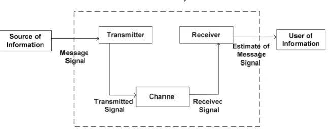
Every communication system consists of Transmitter, Medium of the Transmission and Receiver as shown in Figure 7.
Figure 7: Elements of a communication system
The transmitting end is responsible for generating the message (voice, music, picture, data etc) and the transmitter converts this message into an electrical signal. The transmitter encode the message, this encoded message is multiplied by a carrier frequency and then transmit it to the medium. At the communication channel, fading and noise effects the
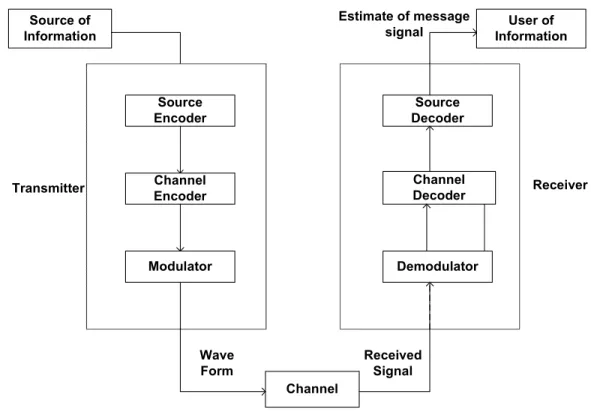
transmitted signal. Then the transmitted signal is propagated over the physical medium. At the receiver end, the received signal is demodulated and decoded to reproduce the original message signal. The whole procedure is shown in Figure 8. A good communication system has minimal distortion at the receiver end.
Channel User of Information Source of Information Transmitter Wave Form Received Signal Source Decoder Channel Decoder Demodulator Source Encoder Channel Encoder Modulator Estimate of message signal Receiver
Figure 8: Communication system
The transmission medium from the transmitter to the receiver can be classified as guided medium and unguided medium. The guided medium is usually the wired communication while the unguided medium is normally based on wireless communication. The Public Switched Telephone Network (PSTN), Optical Fiber Communication, LAN based networks are examples of wired communication and GSM, WLAN, TV broadcasting are examples of wireless communication.
The communication system can also be classified as analog communication and digital communication. The reproduction of analog signal at the receiver end is very difficult due to the presence of transmission medium impairments. Thus, the analog signal is badly effected
by the noise. In comparison the digital systems offers good performance, better efficiency immune to noise. Due to these advantages, digital systems are becoming popular. The modulation scheme also depends on the type of the communication system, i.e., analog or digital. The modulation is defined as the variation of the carrier waves in terms of frequency, amplitude and phase in an electromagnetic wave or signal in order to make it suitable for transmission [23].
Also some other important terms used in any of the communication systems are:
Multiplexer: It is an integral part of transmitter. It is used to transmit different signals through a single medium. While, demultiplexer is used at the receiver end to separate these multiplexed signals.
Multiple Access: It is a method which allows different user wants to share the same channel. There are several multiple access technologies which are as follows:
• Frequency Division Multiple Access (FDMA) • Time Division Multiple Access (TDMA) • Code Division Multiple Access (CDMA)
• Orthogonal Frequency Division Multiple Access (OFDMA)
Channel Coding: The error detection and correction scheme is implemented at the receiver end. It is used to detect errors. These errors are produced because of the noisy channel and fading effects in the transmission medium.
Source Coding: If the bandwidth of the input signal is larger than the bandwidth of channel then source coding is used to process and reduce the bandwidth of the input signal.
2.2 Forms of Communication
Point to Point Communication: In the case of point to point communication, communication occurs between two points that are far away from each other. The most common example of point to point communication is voice call between two end users. Point to Multipoint Communication: In the case of point to multipoint communication, there is only one transmitter at the transmitter end and multiple receivers are present at the receiver end. Video conferencing is an example of point to multipoint communication.
Broadcasting: In this type of communication, all the users receive the transmitted signal. In this scenario, the transmitter is usually at the central location and it sends data to every recipient. Examples of broadcasting are TV and radio.
Simplex: In a simplex mode of communication, the information is sent only in one direction.
Half Duplex: In half duplex mode of communication, we can send the information in both directions but at different time intervals, i.e., from sender to receiver at one time and from receiver to sender at another time. Examples are walkie talkie sets.
Full Duplex: In this mode of communication the information is send to both directions as in Half Duplex but sender and receiver can communicate simultaneously. GSM is an example of full duplex communication.
2.3 Transmission Impairments
The data or information is sent in the form of electrical signals. This electrical signal contains different voltage level that represents different data streams. If the transmission media is ideal, the receiver could receive exactly the same signal that was sent, but communication mediums are generally not perfect, so the signal will be impaired during traversing [17, 18].
These impairments can lead to major errors in digital information. Transmission medium experience four major problems:
1. Attenuation 2. Delay Distortion 3. Noise
4. Fading 2.3.1 Attenuation
Attenuation is the loss of power as the signal propagates in distance and time. Signals must be adequately strong so that the receiver could detect and interpret the signals. If the attenuation is high, the receiver might not be able to identify the signal at all. For reliable communication, attenuation and delay should be constant [20].
2.3.2 Delay Distortion
Delay distortion takes place as a result of different frequency components arriving at different times, which distort the amplitude of signals and also delay the signals by different amounts at the receiver. Factors that introduce delay distortion in a communication channel are:
Reflection: when radio waves collide with a smooth surface that has a length larger than the wavelength of radio waves, then the waves reflect back by making the same angle at which they collided to the surface.
Diffraction: This phenomenon occurs when a signal is obstructed by the edge of a dense body which has larger length as compared to the wavelength of the signal.
Scattering: when a signal strikes a large rough surface with length similar or less to the wavelength of the signal, it scatters into different direction.
2.3.3 Noise
Noise is defined as unwanted energy from sources other than the transmitter. It can be classified into following categories:
• Thermal Noise • Intermodulation
• Inter Symbol Interference (ISI) • Cross Talk
• Impulse Noise
• Additive White Gaussian Noise (AWGN)
Thermal Noise:
Thermal noise takes place due to the thermal disturbance of electrons in a conductor also know as White Noise [4]. It can be calculated using the following formula for a given bandwidth:
N = kTB where:
N = Noise power in watts
k = Boltzmann’s constant. 1.3803 × 10⁻²³ J/K
T = Temperature in Kelvin B = Bandwidth in Hz
Intermodulation:
Intermodulation noise occurs from interference of two signals of different frequencies that are sent through the medium, due to nonlinear characteristics of the medium. When two signals, interfere each other then new frequencies are introduces which produces an unwanted signal that must be filtered out.
It is the alteration of received signal in a digital communication system in which symbols overlap on each other.
Cross Talk:
Cross talk is unwanted noise occurring due to mixing of two signals paths which are closed to each other.
Impulse Noise:
Impulse noise occurs due to voltage spikes in equipments, an unpredictable continuous disturbance caused by lightning and causes errors in transmission.
AWGN Noise:
AWGN is a noise, that effects the transmitted signal when it passes through the channel. It contains a uniform continuous frequency spectrum over a particular frequency band.
2.3.4 Fading
The distortion experienced by a carrier signal during transmission is known as fading and is due to multipath propagation [21, 22]. Fading can be characterized as follows:
Slow Fading: occurs when there is a low Doppler spread spectrum in the channel and the coherence time is greater than the symbol period.
Fast Fading: occurs when there is a high Doppler spread spectrum in the channel and the coherence time is less than the symbol period.
Flat Fading: It occurs when bandwidth of a signal and delay spread is smaller than the channel bandwidth and the symbol period respectively.
Frequency Selective Fading: It occurs when bandwidth of a signal and delay spread is greater than the channel bandwidth and the symbol period respectively.
Rayleigh Fading: When no LOS path exists in between transmitter and receiver, but only have indirect path than the resultant signal received at the receiver will be the sum of all the reflected and scattered waves.
Ricean Fading: It occurs when there is a LOS as well as the non-LOS path in between the transmitter and receiver, i.e. the received signal comprises on both the direct and scattered multipath waves.
The term coherence time is that duration of time in which impulse response of channel is invariant. The time require to complete one symbol is referred as symbol time.
2.3.5 Doppler Shift
Due to the multipath propagation of radio waves, multiple copies of the same signal are received at the receiver end. If the user is moving with some velocity (speed), there is a shift of frequencies in each of these received signals. This process is known as Doppler shift.
f
d= (vf
c/λ)cos(α)
where, fd is the Doppler shift frequency, v is the velocity of moving object, λ is wavelength
C
H A P T E R
3
Orthogonal Frequency Division Multiplexing
3.1 Need for OFDMOFDM modulation technique combines the concepts of modulation and multiplexing. It exists in research laboratories and text books for a quite long time but in the last decade the rapid changes in modern communication system employed OFDM in digital radio and wireless data networking. Now-a-days, OFDM is practically used in several new wireless communication technologies. Here the question arises on why this OFDM technique became so popular. OFDM is basically a special case or derived from the Frequency Division Multiplexing (FDM), and extends the concept of single carrier modulation [25]. A single carrier spectrum modulation technique modulates all the information using a single carrier in terms of frequency, amplitude or phase adjustment of the carrier. In case of digital communication single carrier is used. If there is an increase in the bandwidth of the system then the duration of one symbol decreases. This causes the system to be more susceptible from noise, reflection, refraction, scattering and other impairments that introduces errors in the system. The block diagram of the single carrier modulation is shown in Figure 9.
3.2 Multicarrier Modulation
The basic motto of using the multicarrier modulation is to achieve good data rates with minimum or least ISI. To acquire a channel which has no ISI it is required that the symbol time Ts should be more or greater than the channel delay spread time ד and if the symbol
time approaches or falls below the channel delay spread time then the BER becomes unacceptable and the system is intolerable [26].
To overcome the problem of ISI the concept of multicarrier modulation is used in which a high data rate bit stream is divided into many lower rate bit streams (L). These individual bit stream are further divided into L parallel sub channels that maintain the ISI and the desirable data rate can be achieved through Ts/L>>ד and hence achieve a channel that is free of ISI.
These sub channels are orthogonal to each other and because of this the modulation is also called OFDM. The data rate in any of the single sub channel is less than the total date rate. Similarly, the bandwidth of a single channel is very small than the total bandwidth. Due to this, the sub channels experience relatively flat fading. The concept of orthogonality can be defined in a way that the carrier wave is either sine or cosine wave and the area of one period of sine or cosine wave cancels each other and becomes zero as shown in Figure 10.
At the transmitter, a single stream that carries higher bandwidth B is divided into L narrow band parallel sub streams. This process is done through serial to parallel convertor. These individual streams have a data rate of R/L with bandwidth B/L as shown in the Figure 11.
S/P X X X
+
R/L bps R/L bps R/L bps ) c 2 cos(π
f +∆f ) ) 1 ( c 2 cos( πf + L− ∆f ) c 2 cos( πf ) t ( x R bpsFigure 11: OFDM transmitter
After passing through the medium the signal is received at the receiver end where L numbers of demodulators demodulates the received sub streams and then passes them through low pass filter. Further, all the sub streams are then passed through parallel to serial converter to get back the original signal.
) ) 1 ( c 2 cos( πf + L− ∆f ) c 2 cos(πf +∆f ) c 2 cos( πf
Figure 12: OFDM receiver
3.3 Basics of OFDM
OFDM is a mixture of multiplexing (sharing of bandwidth between different channels) and modulation (scheme for transfer of information over carrier). Furthermore OFDM divide the bandwidth of the transmission medium into various narrowband subchannels. Then on these parallel subchannels data is transmitted to overcome frequency selective fading.
3.3.1 OFDM Guard Band Intervals
In OFDM the data symbols are grouped in a block and called OFDM block symbols. A block consists of T seconds can be formulated as.
LT
T = (1)
where, L is the number of sub stream and Ts is the time of one symbol to complete. In order
to avoid interference among symbols while they pass through a wireless channel, the guard time is introduce between the OFDM symbols. The guard time, Ts which is greater than the
channel delay spread time ד then in that scenario, OFDM symbols only experiences the interfere with itself. If the guard time between the two consecutive symbols is increased then rectification of the symbol interference is possible.
Figure 13: OFDM guard band interval
3.3.2 Circular Convolution and Discrete Fourier Transform (DFT)
As the OFDM symbols are orthogonal to each other with some guard interval between the two blocks. In order to remove the ISI within an each OFDM symbol, the concept of circular convolution is used. Since every discrete system has an input data x[n] that is sent over the channel having Linear Time Invariant (LTI) impulse response h[n]. The output of this system is y[n] and that is the circular convolution of the input signal with the impulse response of the channel [24].
[ ]
n = x[ ]
n ⊗h[ ]
n =h[ ]
n ⊗x[ ]
ny (2)
For getting the frequency response of the system DFT is applied on both sides of the equation 2 and hence get the transfer function H[z].
y[n]=
[ ]
[ ]
[ ]
[ ]
∑
[ ] [
]
− = − ≅ ⊗ = ⊗ 1 0 L k k n x k h n x n h n h n x (3) 3.3.3 Cyclic PrefixOFDM uses cyclic prefix to achieve a channel which is free from ISI. This is accomplished by using circular convolution as explained in 3.3.2. Each OFDM symbol is inserted with a cyclic extension of length L that is greater than the delay of the channel as shown in the Figure 14.
Cyclic prefix combats against ISI in a very simple manner but it degrades the data rate and efficiency of the system. If multipath delay in the channel is less than the prefix then system will not observe any ISI or ICI (Intercarrier Interference) [26].
Figure 14: OFDM cyclic prefix extension
3.3.4 Frequency Equalization
In order to get the complex channel gain of the system, it is necessary that the amplitude and phase of all the subcarriers is known to the receiver. For example BPSK and QPSK are modulation schemes that do not bother about the amplitude at which the information is transmitted as they are only concern about the phase [27].
Fast Fourier Transform (FFT) is performed to calculate the frequency equalizer response as under which is as follows:
(4) where, Xl is an estimated input. Yl is an output. Hl is transfer function.
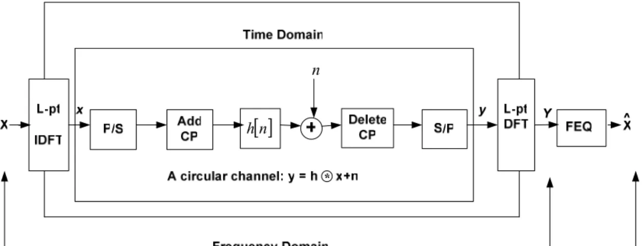
3.3.5 Block Diagram of OFDM System
The block diagram of OFDM is defined in a way as follows [24, 35]:
i. Firstly a wideband signal having B bandwidth is breakdown into L narrow bands with each having bandwidth of B/L. By doing so, the system has maintained its aggregate symbol rate with no ISI. Cyclic prefix is used to increase the delay spread. Hence, each subcarrier experiences flat fading.
ii. The information is sent through a channel by using L narrowband radios. Therefore, L narrow bands are modulated and after that IFFT technique is applied on those bands.
iii. IFFT is used to split the ISI channel in the form of orthogonal subcarriers. Cyclic prefix must be added after the IFFT operation and then the resulting symbol are sent serially through the wideband channel.
iv. At the receiver end, first cyclic prefix is removed then serial wideband spectrum is converted into L narrow band spectrums. After that these bands are demodulated using FFT operation which yields L data symbols.
v. Every subcarrier can be equalized through Frequency Domain Equalization (FEQ). In FEQ, it is assumed that transmitter and receiver are perfectly synchronized with each other and the channel conditions are known by the receiver. Xl Yl Hl =
[ ]
n hn
Figure 15: OFDM block diagram
3.3.6 Synchronization & Peak to Average Ratio (PAR)
There are two types of synchronization namely timing and frequency synchronization and these are required to demodulate the OFDM signal at the receiver end. In the timing synchronization, there is a need to determine the timing offset of the symbol and then the optimal timing instants. Whereas in the frequency synchronization, at the receiving end, the receiver must align the carrier frequency of the received signals as much as possible. In OFDM, the timing synchronization is achieved more easily because the OFDM symbol structure have a reasonable degree of synchronization error but frequency synchronization is more stringent to achieved because OFDM have narrow bands signals which have their individual frequency domain and are orthogonal to each other.
The other important parameter in is OFDM high Peak to Average Ratio (PAR) which is also called as Peak to Average Power Ratio (PAPR). It is defined as the ratio of peak instantaneous value to averaged time. The PAR is used to determine many parameters of the signal, such as current, voltage frequency, power and phase. The reason for high PAR is that in OFDM or multicarrier signal is the summation of many carrier signals. Due to this, its value is very high large and very small at different time intervals. These abrupt changes in PAR value introduce a challenge related to the implementation of OFDM. The PAR
problem reduces the efficiency and to overcome this problem there is a need to increase the RF power which needs an amplifier and this increases the cost of the system because the power amplifier is the most expensive components in radio communication.
3.4 Orthogonal Frequency Division Multiple Access
The greatest challenge of WiMAX is to provide the high information rate efficiently in limited bandwidth to multiple users in the same vicinity. To conquer this challenge WiMAX uses Orthogonal Frequency Division Multiple Access technique in version 802.16e through which users shares time slots and sub-carriers.
3.4.1 Multiple Access Strategies
Multiple access strategy combines many signals/streams into one to share the communication medium based on method known as multiplexing. Following are the most widespread access methods:
3.4.1.1 Frequency Division Multiple Access
FDMA is the first multiple access technique used when a continuous transmission is usually required for analog cellular communication. In this technique, the bandwidth is distributed amongst different channels and users can use finite portion of that bandwidth. In an OFDM system the FDMA can be easily implemented by assigning set of subcarriers to each user.
There are number of ways through which the allocation of this technique can be performed. The simplest one is static allocation of subcarriers for every user. For example in 128 subcarrier OFDM system it could be possible that user 1 gets 32 subcarriers, i.e., from 1 to 32. In a similar manner user 2, 3 and 4 get subcarrier 33 to 64, 65 to 96 and 97 to 128 respectively. The allocation is implemented before the IFFT operation with a multiplexer for various users. Practically, it could be possible that the allocation can occur in such a way that there are more subscribers having lower data rates.
Another way to implement this technique which is basically an improvement of the static technique is through dynamic subcarrier allocation that depends on channel state conditions.
Figure 16: Frequency division multiple access
3.4.1.2 Time Division Multiple Access
TDMA is used in digital system where there is no need of continuous transmission because users do not utilize resources or do not use the available bandwidth all the time. For example the GSM uses TDMA as a multiple access technique. In this technique, the users utilize the entire bandwidth of the system but only for some finite duration. Each user is allocated time slots in which the entire bandwidth of channel is on user’s disposal. As compared with FDMA, TDMA system can accommodate more users and multicarrier modulation uses both these techniques.
TDMA is an appropriate scheme for constant data rate and circuit switched applications such as, telephones and video conferencing but it is not used in WiMAX system. WiMAX uses more sophisticated algorithm which is based on scheduling of queue lengths, delay constraints and channel conditions.
Figure 17: Time division multiple access
3.4.1.3 Code Division Multiple Access
In CDMA scheme, all users are assigned separate codes which are orthogonal to each other and all users have same bandwidth. The method which is used for assigning the codes to users is known as Welch Code Method. CDMA uses spread spectrum technique for spreading the signal. CDMA is not appropriate for high speed data because its premise is that bandwidth that is larger as compared to data rate is used for interference suppression.
Multicarrier CDMA waveform can be created if OFDM and CDMA schemes are combined. In OFDM it is possible to separate the users through codes by using the spread spectrum technique either in time or frequency domain.
Code
Time
Frequency
Figure 18: Code division multiple access
3.4.2 OFDMA Resource Allocation Technique
The advantage of multiuser diversity and adaptive modulation in OFDMA systems can be implemented through different algorithms. The algorithms are designed for determining how to schedule the users for allocating of subcarriers to the users and to find out the power level on each subcarrier for every user [37].
The resources allocation techniques are designed or formulated in a way that its focus is on constrained optimizing problem. Constrained optimizing problems are as follows:
i) To minimize the total transmit power. ii) To maximize the total data rate.
The following algorithms are used for resource allocation in OFDMA systems.
a) Maximum Sum Rate Algorithm (MSR). b) Maximum Fairness Algorithm (MF).
d) Proportional Fairness Scheduling (PFS)
The performance of the above mentioned algorithms can be judged through throughput and fairness or the power level at each subcarrier.
3.4.3 OFDMA Protocols in WiMAX
As discussed previously the resource allocation techniques in OFDMA are primarily focussed the OFDM subcarriers and the power that each user utilizes r. Now the protocols of OFDMA system in accordance with the algorithms are given in Table 3.
Algorithm Capacity Fairness Complexity MSR Best Poor, Inflexible Low
MF Poor Good, Inflexible Medium PRC Good Best, Flexible High
PF Good Flexible Low
Table 3: OFDMA protocols
The protocols defined in OFDMA are dependent on the following:
Sub Channelization:
In WiMAX systems the subcarriers are distributed not on individual basis but on blocks of subcarriers that are allocated to users. This is done to reduce the complexity of the subcarrier allocation algorithm and to simplifying the mapping messages. This can be clearer by assuming that m number of users is allocated a block of Bm subcarriers. These subcarriers can be either spread out over the total bandwidth, i.e., distributed subcarrier permutation, or on the basis of frequency range, i.e., adjacent subcarrier permutation. The primary advantage of distributed permutation is robustness and improvement in frequency diversity while in the case of adjacent permutation; the major advantage is increase in multiuser diversity [39].
Mapping Messages:
In WiMAX networks, every mobile user knows which subcarriers are allocated to them. For the distribution of subcarriers, BS broadcasts information to every MS through downlink (DL) MAP messages. The BS also tells the MS which subcarriers are used to transmit in an upward direction using uplink (UL) MAP message. Along with the information of the UL and DL subcarriers, the MS also knows about the burst profile used in the UL and DL subcarriers. The burst link is measured on parameters like Signal to Interference and Noise Ratio (SINR) and Block Error Rate (BLER) for both links and identifies the level of coding and modulation.
Ranging:
Every MS have always some distance from the BS and critical parameters related to network optimization, i.e., uplink is used to synchronize symbols and it also equalizes the received power levels between different active subscribers, this process is called as ranging. It is very important that all users are synchronized in the uplink direction at least within a cyclic prefix guard time while the download link is already synchronized. If the uplink carrier is not synchronized then severe inter carrier and inter symbol interference is introduced in the system. Also power control is recommended at the downlink end to limit the cell interference.
3.4.4 Advantages of OFDMA
OFDMA system has the following advantages:
• OFDMA offers a single user OFDM with respect to frequency diversity and robust
multipath suppression.
• OFDMA systems can accommodate many users through flexible multiple access
techniques.
• It offers a variety of applications, data rates and QoS features.
• OFDMA integrates algorithms in the time and the frequency domain in order to
serve user population in an efficient way.
• OFDMA system relates to OFDM. It has all the potential to minimize the
transmitter power and PAR problem.
Modulation & Coding
4.1 Digital Modulation
Modulation is the technique used for modulating the digital information via satellite, microwave, or cable pairs. The basic motto of digital modulation is to transport or convey digital data between two or more nodes. This can be achieved in radio communication by adjusting the carrier signal usually sinusoidal in nature. The carrier signal is adjusted with respect to phase, amplitude and frequency or a mixer of these. In real systems, it can be achieved by using modulator at the transmitting end and demodulator at the receiving end [33].
Figure 19: Digital modulation
There are three important types of digital modulation which are as follows:
• Amplitude-Shift Keying (ASK) • Phase-Shift Keying (PSK) • Frequency-Shift Keying (FSK)
These techniques use the parameter of a sinusoid to show the information which we need to send. Sinusoid depends on three different parameters namely; phase, frequency, and amplitude. The process of modulation is a process that takes voice in the form of signal most probably a sine wave and then it is transmitted.
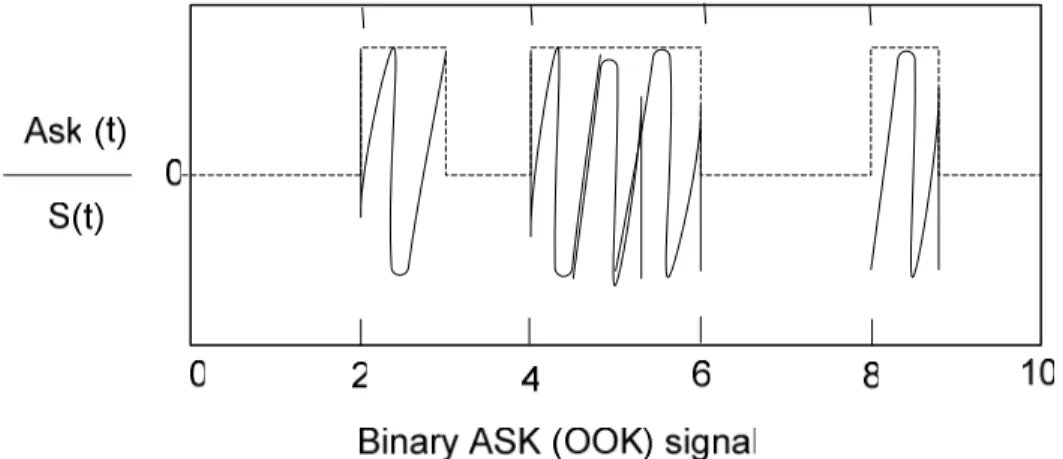
4.1.1 Amplitude-Shift Keying (ASK)
Amplitude Shift Keying is the method in which the amplitude of carrier is changed depending on the information while frequency and phase is kept constant. In ASK, the bit which carries signal “1” is transmitted by some particular amplitude of a carrier. In case of transmit 0 usually the amplitude is kept to be zero. A special form of ASK is ON-Off [28].
Figure 21: Binary amplitude shift keying (On-Off Keying)
4.1.2 Frequency-Shift Keying (FSK)
In Frequency-shift keying the amplitude and phase of the signal are kept constant while the frequency is continuously changed with respect to signal. The two logic binary states of 0 and 1 are represented by an analogue waveform. In FSK, both 0 and 1 are represented by different frequency waveforms. Logic 0 has lower frequency as compared to the logic 1 [29].
4.1.3 Phase-Shift Keying (PSK)
Phase-shift keying (PSK) is the mode of communication in which the phase of the transmitted signal is varied. The PSK has many methods but the simplest one is referred as Binary Phase Shift Keying (BPSK). In PSK the amplitude and frequency of the signal remain constant while the sinusoidal carrier gives the information of the phase change [30].
4.2 Binary Phase Shift Keying (BPSK)
The BPSK is a binary level digital modulation scheme of phase variation which have two theoretical phase angle i.e. +90o and -90o. This gives high immunity against the interference
and noise and a robust modulation which gives improved BER performance. BPSK phase modulation uses the phase variation to encode the bits; each of the modulation symbols is equal to the one phase.
Figure 22: BPSK constellation
4.3 Quadrature Phase Shift Keying (QPSK)
If there are 4 phases that consists of 0o, 90o, -90o and 180o then the M-ary PSK is termed as Quadrature Phase Shift keying (QPSK). It is used when there is a requirement of higher spectral efficiency (in b/s Hz). It uses more symbols as compared to BPSK. In QPSK, the number of bits used per symbol is two-bit of modulation symbols. Fig 4.1 shows the function of the modulation symbol of the possible phase value.
Figure 23: QPSK constellation
QPSK always has a constellation of four points. At the receiver end, the decision is made between two bits e.g. symbol 00 and 01.
The modulation of QPSK is therefore the noise-resistance than BPSK as it has interference which is smaller than BPSK.
Even Bits Odd Bits Modulation Symbols φk
0 0 00 π/4
1 0 01 3 π /4
1 1 11 5 π /4
0 1 01 7 π /4
Table 4: QPSK signal space characterization
The digital communication is based on a well know principle that is “Greater symbol rate for modulation is more spectrum efficient but it is less robust”.