MASTERTHESIS 2014
Master in Product Development with a specialization INDUSTRIAL DESIGN
Industri
DESIGN
MASTER THESIS PROJECT
ION: CONCEPTUAL DEVELOPMENT OF A PEDELEC
DANIEL HEGESTRAND
This thesis is performed at the Technical University of Jönköping in industrial design. The author is responsible for the stated opinions, conclusions and results.
Examiner: Lars Eriksson Supervisor: Magnus Andersson Extent: 30 points (D-level)
Summary
This project was conducted in collaboration with Emtes Autotech and Berge consulting with the goal to develop and design an electric pedelec for general and off-road use. The idea behind the pedelecs Is to introduce something that can both be used as a source for everyday transportation, and as a source of fun exercise. The idea behind this is to incorporate a stronger engine into the pedelec, giving it an increase in force, acceleration and speed.
The thesis is written in the field of industrial design and will take the reader through a typical design process. The project will start with a design brief that is formulated with the client and continue into understanding the problem by analyzing the target consumer, the market and other factors of interest. The project will then go into an ideation face that explores opportunities found during research and finish with a worked-through concept that in the end was presented as a full-scale model.
Methods used during the project are among others: Bootleg Bootcamp, Gannt-schedule, Functional analysis, Trend analysis, Parts breakdown structure, Competitor analysis, Image board, Brainstorming, CAD-modelling and Rapid prototyping.
Keywoards: Industrial design, Pedelec, Electric vehicle, Design, Product development.
Table of contents
Summary... i
Table of contents... ii
1
Introduction ... 1
1.1 BACKGROUND ... 1 1.2 OBJECTIVES ... 1 1.3 DELIMITATIONS... 2 1.4 DISPOSITION... 22
Theoretical background ... 3
2.1 DESIGN ... 3 2.1.1 Why design? ... 3 2.2 DESIGN THINKING ... 4 2.3 DESIGN DOING... 4 2.4 DESIGN BRIEF... 5 2.5 DESIGN METHODS ... 62.5.1 The “Double diamond” ... 6
2.5.2 Bootcamp Bootleg ... 7
2.5.3 Double diamond VS Bootcamp Bootleg ... 8
2.1 AESTHETICS AND THE INTERPRETATION OF FORM ... 9
2.1.1 Aesthetics and perception... 9
2.1.2 The Gestalt ...10
2.1.3 Semantics ...13
2.2 THE BICYCLE ...16
2.2.1 Trail ...16
2.2.2 Fork angle...17
2.2.3 Wheelbase and weight distribution...17
2.2.4 Bottom bracket drop...17
2.2.5 Chain stay length...17
3.3 TREND ANALYSIS ...18
3.4 PBS(PRODUCT BREAKDOWN STRUCTURE) ...19
3.5 COMPETITOR ANALYSIS...19
3.6 SWOT ANALYSIS ...19
3.7 IMAGE BOARD ...20
3.8 BRAINSTORMING ...20
3.9 IDEATION AND SKETCHING ...20
3.10 CAD-MODELLING ...21
3.11 PHYSICAL MODEL ...21
3.12 RAPID PROTOTYPING ...21
4
Approach and implementation ... 22
4.1 STARTUP ...22
4.1.1 Project description and Design brief ...22
4.1.2 Planning ...23
4.2 EMPATHIZE ...24
4.2.1 Upcoming trends and future scenario ...24
4.2.2 Product/user analysis ...25
4.3 DEFINE ...26
4.3.1 Rules and regulations ...26
4.3.2 PBS (Product Breakdown Structure)...28
4.3.3 Persona...29
4.3.4 Proportions ...30
4.3.5 Bicycle VS Enduro motorcycle ...31
4.3.6 Market analysis ...32
4.3.7 SWOT...33
4.3.8 Image board ...34
4.3.9 Form study...35
4.4.3 Evaluation 1...41 4.4.4 Ideation 2 ...41 4.4.5 Ideation 3 ...42 4.5 PROTOTYPE/TESTING ...48 4.5.1 Configuration 1 ...48 4.5.2 Configuration 2 ...49 4.5.3 Configuration 3 ...50 4.5.4 Evaluation ...51 4.5.5 Decision ...51 4.6 REFINE ...51 4.6.1 Refine 1...52 4.6.2 Refine 2...52 4.6.3 Refine 3...53 4.6.4 Refine 4...53 4.7 CAD-MODELL ...54 4.8 PHYSICAL MODEL ...55 4.9 DELIVER ...57 4.10 RESULTS ...58
4.11 THE FINAL CONCEPT,ION ...58
4.12 FEATURES ...59
4.12.1 System integration ...59
4.12.2 Lightweight construction...60
4.12.3 Power supply...61
4.12.4 Gearbox ...62
4.12.5 Quick grip saddle adjustment ...63
4.13 PHYSICAL MODEL ...64
5
Conclusion and discussion... 65
6
References ... 67
6.1 PICTURE REFERENCES...69
Introduction
1 Introduction 1.1 Background
Electric vehicles are becoming more and more common in today
environmental conscious society, booth in the form of cars, motorcycles and maybe most of all bicycles. The market is mostly made out of pedelecs with a help engine designed to assist the user in steep climbs or when the user simply doesn’t have the energy to move the vehicle forward.
With electric components decreasing in cost, people has started taking it in their own hands to build and design their own pedelecs, taking it a step even further. Hence a new product has started to show up in forms of home built pedelecs with a stronger engine and larger battery capacity. This product functions more as a hybrid product, a mix between a motorcycle and a bicycle.
Since this product is a hybrid, some compromises has been made in the design or the performance of the product. Some are heavy, some lack power and some simply have a bad form language that doesn’t appeal to the user. What this project pursues is how to come up with a product with no or very few compromises. A product that mixes the best parts of two worlds, a motorcycle and bicycle combined into a new form of transportation.
1.2 Objectives
The objectives with the project is to perform a background study around the product and design a product that are customized for these needs. Questions that are relevant are: What does the market look like? Who is the target consumer and what are their needs? Who are the competitors and where and when are the product to be used?
The project will result in a full scale model of the concept that will be presented on the final exhibition on the fourteenth of May.
Introduction
1.3 Delimitations
Some time ago, Emtes engineering started up a similar project and bought parts that would be fitted to the product. These components are considered to be applied to the new concept, hence they compose the constraints. The parts that are pre-determined are:
• Electric engine, 6 kilowatts • Planetary gearbox
• Battery cells, litium-polymere • Front and back suspension • Front and back break • Steering
• A deeper analysis in the strength of the construction will not be carried out to limit the size of the project.
• The report won’t go deep into any manufacturing process nor cost analysis.
1.4 Disposition
The report starts with a theoretical background that deepens the readers understanding of what design is, the way designers work and the
environmental movement concerning electric vehicles. The report then goes through the different tools and methods that are applied to the project to better understand the approach and implementation, which discloses how the
project was conducted. Finally, the report leads to the conclusion of the project where the reader can review results and ends with the writes conclusions and reflections concerning the project.
Fel! Hittar inte referenskälla.
2 Theoretical background
2.1 Design
According to Kenneth Österlin (2011) when talking about design, many thinks about the aesthetics properties of an object and making an it visually appealing. What’s important in this scenario is to divide the different areas of expertise. Österlin claims that design can relate to someone who purely focus on form. While at the same time, an industrial designer focuses on designing products that are adapted to the target consumer and the limitations of production. Lawson (2006) claims similar to Österlin that design focuses on solving a real-world problem, while art is more or less self-motivated and focuses more on expressing the individual’s inner thoughts. While this is true, the designer still needs to be in contact with the artistic or imaginative side. Great imagination to come up with new ideas and the logic to evaluate them, hence the control of both sides is essential to be a good designer.
2.1.1 Why design?
According to Ullman (2010), the design project often starts out of three possible scenarios. The first scenario is that there is a technological pull, meaning that there can be new technology that opens new doors to product development. The second scenario is that there is a market pull, meaning that there is a need that needs to be fulfilled on the market that the product developer can fill. An example of this is when a company called Oculus rift started developing virtual reality goggles (The history of Oculus Rift, 2017). The gaming industry noticed that the product gained great interest among their target consumers and since the product is linked to the same hardware (personal computers), the gaming industry started developing games to fit Oculus Rifts virtual reality goggles. They simply noticed a market pull for that kind of product. The third is simply product change. The company needs to update an outdated
product by making small changes to an already existing solution.
Once the goal is set, the design process is applied to the problem to come up with a solution. The process is a manner of working that focus on stimulating creative thinking and translating information into needs to finally come up with a finished product. Design thinking into design doing.
Fel! Hittar inte referenskälla. 2.2 Design thinking
Design thinking can be described as a variety of processes designers use when trying to solve a problem. Rather than the processes thou, design thinking is about how the designers choose to address the problem. While traditional problem solving is focused around targeting the problem, designers focus on the goal.
This manner of thinking opens up for a more creative way of thinking. Tim brown (2009) claims that designers work around convergent and divergent thinking. You can picture this as a type of funnel. Initially the designer thinks wide, creating wild ideas while leaving no room for the analytical part of the brain. This is called the divergent phase. Once this step is done, the ideas goes through the funnel and the essence of the ideas are kept for further development. This is called the convergent thinking.
Lawson (2006) calls this way of thinking imagining and reasoning. During the
divergent phase the imagining takes place which is a sort of “day dream” state where the individual uses own experiences and feelings to explore ideas. The reasoning, which is more purpose driven takes place during the convergent phase. This state often includes a more logic and problem solving approach.
2.3 Design doing
“Design is fundamentally of making something new. It is not an attribute, it is fundamentally about action” (Fraser H, 2006)
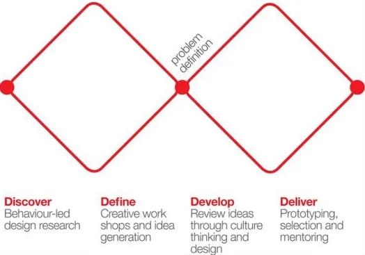
While the process of applying design thinking vary greatly, there are similarities in how design firms apply it. The Design Council performed a study of the process among eleven leading design firms to see how they worked, they found many similarities among the different approaches the firms used. The key factors of their processes were mapped into a model that is called the Double Diamond design process model.
Fel! Hittar inte referenskälla. 2.4 Design brief
“Excellent or even good solutions to a problem do not come out of thin air. They are created on the basis of good problem statement”
(Jens Bernsen, 1996)
A design brief is a written document that is constructed early in the design process. The brief is constructed between the client and the designers and contains the delimitations and constraints of the project. This is made to ensure the focus of the project is understood and clear to both the designers and the client.
The function of the brief is to lay down the general aim and goals of the assignment but also to act as a checklist to make sure that the goals has been reached. The brief should also be revisited along the way and change depending on new facts and information that turn up during the project.
Following Bernsens guidelines to constructing a design brief, it should contain the following
• Identify what the new product wants to be • Describe the basic functions of the product • See the product the way the user sees it • Describe the personalities of user and product
• Describe the features that determine the experienced value
• Describe the product’s reflection of and contribution to the image of the company
• System design: Indicate the extent to which a new product should associate itself with a product system
• Identify the elements that determine the experienced “technical quality” of the product
• Tell a good story. Create a product idea that can be communicated • Create good environmental qualities and make them visible
• Concentrate the brief on essential things • Revise the brief from time to time
Fel! Hittar inte referenskälla. 2.5 Design methods
2.5.1 The “Double diamond”
The Double Diamond model revolves around different phases during the design process where convergent and divergent thinking is applied. It usually starts with an idea that needs to be explored further by analyzing the end user and the market. The data collected are then reviewed and explored throughout the define phases which ends up with a problem definition that will work as a central part of the project. Tim Brown (2009) claims that the challenge with design thinking is to help people articulate the latent needs that they may not even know that they have. Hence coming up with a clear problem definition can prove to be harder than initially thought, but by doing a good research early in the project, expenses further on can be avoided.
It is important to keep in mind that this is an iterative process where the problem definition can be revised depending on the finds that come up during the project. The designers then start developing a concept into something more realizable, usually by building and testing CAD- and physical models. The final step is to deliver the
concept and depending on the project, what is to be presented varies greatly. All from a 3D-model to a fully functional prototype and more.
Double diamond (2017)
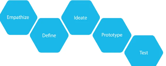
Fel! Hittar inte referenskälla. 2.5.2 Bootcamp Bootleg
Bootcamp bootleg is a collection of processes that was worked out by the Institute of Design at Stanford. The collection describes the different steps the designer needs to consider when designing out of a user experience point of view. These several steps are similar to many other design processes where the main focus lies in
understanding the problem before solving it. While the process starts from A and ends at B, it is considered an iterative process, meaning that finds during the process will lead to the designer taking a step back to evaluate the problem with these new parameters. The different steps are Empathize, Define, Ideate, Prototype and Test.
Figure 2.2, Bootcamp Bootleg
Empathize
Empathize is the first phase of the design process where the designer focuses on understanding the problem and the user. This is done by observing the user and the context of their lives, by interacting and by getting engaged with the user. Finally, the designer immerses him/herself in the problem to better understand the experience of the user.
Define
The define phase is focused primarily on two goals: to develop a deeper understanding of what was found during the empathize phase, meaning understanding the user and the design space and defining these in a problem statement, for example a design brief. The statement should be formulated in a way that inspires and provides fuel to the creative thinking of the people involved in the
Fel! Hittar inte referenskälla. Ideate
The ideate phase is the creative phase where the focus lies on producing allot of different ideas that fulfill the delimitations and opportunities stated in the define phase. The idea here is to go wide in the beginning, focusing on quantity to make sure that all the ideas are counted for. These are then evaluated and refined while simultaneously narrowing down concepts to finally end up with the ones that are presumed to be the best ones.
Prototype
Once the final ideas have been visualized, it is a good manner of working to produce prototypes to actually test the ideas in the real world. Depending on the timeframe of the project, the level of the prototype can vary from a simple paper models to fully functional prototypes.
Test
In the test phase, the prototype is evaluated to get a “feel” for the concept and work out errors and find better solutions. This is as earlier mentioned an iterative process, meaning if the concept is concluded to work in a sufficient way, it will be finished. If not, it will be brought through the process again and refined further. Stanford states here that the designer should “Prototype as if you know you´re right, but test as if you know you´re wrong”
(Bootcamp Bootleg, 2016)
2.5.3 Double diamond VS Bootcamp Bootleg
When comparing the processes Double diamond and Bootleg Bootcamp, there are allot of similarities to how the different methods address the design process. They both start by defining the core idea of the product and working it into a checklist of what needs to be solved. Once the checklist is set, they both continue on by producing concepts and ideas that later are evaluated and tested until a viable concept is produced.
The main difference between the two processes that can be discerned is that
Bootcamp Bootleg is more heavily focused on human centered design. By bringing in the target consumer into the equation, the designer can use these tools to better understand their needs and demands.
Another difference is that the Double diamond process is more of a general process where the designer needs to bring his or her own tools to solve problems while
Bootcamp Bootleg provides the designer with a great variety of tools for each step on the way. One could say that for unexperienced designers, Bootleg Bootcamp is the way to go while experienced designers can adapt their tools to the double diamond to tailor the process to their taste and company.
Fel! Hittar inte referenskälla. 2.1 Aesthetics and the interpretation of form
Grasping the idea of how we perceive objects around us and how to formulate an idea around an object can many times be rather difficult to comprehend. While our perception of an object is colored by our background and upbringing, there are some rules that describe how we perceive objects around us.
2.1.1 Aesthetics and perception
“Design with particular emphasis on the relation between product and man, e.g., semiotic, ergonomic and aesthetic aspects of the product”
(Endrea 2001)
“The creation of the gestalt of useful products intended for mass production, with the aim of adapting the to Man and his environment”
(Monö, 1997)
When talking about what design or industrial design is, there is no single answer to the question. But when comparing the thoughts of Endrea and Monö, one can
understand that it is related to formulating an understanding between the product and the individual. To better understand this relation, one must understand the meaning of aesthetics.
The word aesthetics derives from the Greek word aisthetes and means One who
perceives. When we perceive things, it is not limited to just the visual spectrum but all
our senses. Meaning we perceive by listening, touching, tasting, seeing, and
smelling. During this thesis, we will mainly focus on how we use our sight and touch to perceive our surrounding but it is still worth mentioning that all the senses play a part.
How long does it then take to formulate an idea (perceive) a product? Do we like it or not? Research show that it takes around 200-250 milliseconds to decide if we like or dislike something. This is called pre-attentive global processing, better known as intuition. After pre-attentive global processing comes attentive perception which is defined by personal interest, background, taste and needs. We use attentive
perception to analyze the patterns, form and details to formulate an understanding of the product. Even thou we understand how we perceive objects, it doesn’t bring us closer to an answer to why we like certain objects and dislike others. This brings us to the understanding of the Gestalt.
Fel! Hittar inte referenskälla.
2.1.2 The Gestalt
The word Gestalt originates from the German word “Gestalt” which means pattern. The way Monö describe the gestalt is that it is “an arrangement of parts that appear
and functions as a whole that is more than the sum of its parts” (Monö,1997).
Roughly one could say that understanding the gestalt is to understand the
composition of patterns that work in harmony and correlate to eachother. The brain is by default wired to find meaning in everything, such as patterns and forms but to better understand these patterns, there is a certain set of laws or rules that we apply. The rules of Similarity, Continuation, Closure, Proximity and Figure/Ground, also called the gestalt laws.
(Monö, 1997)
Figure 2.3, The Gestal
2.1.2.1 Similarity
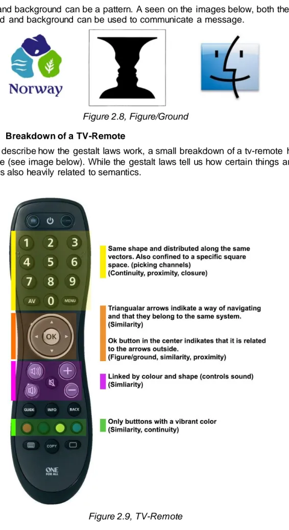
Objects or features that are of the same shape, configuration or color are perceived to belong to a pattern. For example, buttons on a tv remote can have similar shapes or colored in certain themes to represent that they support similar functions.
Fel! Hittar inte referenskälla.
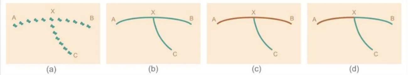
2.1.2.2 Continuity or the good line
Objects that seem to follow the same vector or direction tend to be perceived as a pattern.
Figure 2.5, Continuity
2.1.2.3 Closure
Lines or objects that enclose an area create patches that are easier to perceive as a whole.
Figure 2.6, Closure
2.1.2.4 Proximity/Symmetry
Objects that are placed close- or symmetric to each other tend to be perceived as a pattern.
Fel! Hittar inte referenskälla. 2.1.2.5 Figure/Ground
Both for and background can be a pattern. A seen on the images below, both the foreground and background can be used to communicate a message.
Figure 2.8, Figure/Ground
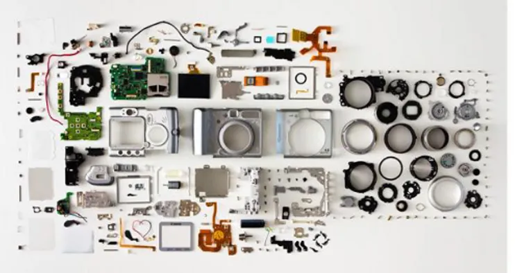
2.1.2.6 Breakdown of a TV-Remote
To better describe how the gestalt laws work, a small breakdown of a tv-remote has been done (see image below). While the gestalt laws tell us how certain things are linked, it is also heavily related to semantics.
Fel! Hittar inte referenskälla. 2.1.3 Semantics
Semantics is the study of “the sign” and the meaning of it in all forms of
communication. A sign can in this context for example be when the train blew its whistle at the train station, indicating that the train soon will leave. The sign can also be related to our sense of smell, for instance we look for fire when we smell
something burning. When designing a product, we apply our understanding of semantics to communicate with the user. By doing so, we increase the users
understanding of the product and its s functions which in term increase the attractivity and pleasure of using the product.
When working with semantics we look at four different areas that we want to enforce. These areas are: Describe, Express, Exhort, and Identify.
(Monö, 1997)
2.1.3.1 Describe
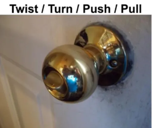
Describe refers how we want the product to be used and in what context. For instance, a handle with a ribbed surface can indicate that it Is intended to be turned while a handle that is flat is intended to be pushed or pulled (see example below)
Fel! Hittar inte referenskälla.
2.1.3.2 Express
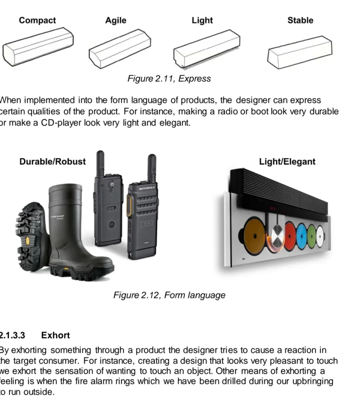
Express refers to what sensation the product refers to. Does it feel agile? compact? Heavy? The designer may use the form language to express different sensations in a product. This should correlate to the brands values and position.
Figure 2.11, Express
When implemented into the form language of products, the designer can express certain qualities of the product. For instance, making a radio or boot look very durable or make a CD-player look very light and elegant.
Figure 2.12, Form language
2.1.3.3 Exhort
By exhorting something through a product the designer tries to cause a reaction in the target consumer. For instance, creating a design that looks very pleasant to touch we exhort the sensation of wanting to touch an object. Other means of exhorting a feeling is when the fire alarm rings which we have been drilled during our upbringing to run outside.
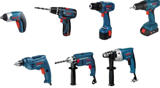
Fel! Hittar inte referenskälla. 2.1.3.4 Identify
Identify refers to identifying the origin of the product and its affiliated siblings (product family) and understanding its purpose. For example, a company starts up by building and selling a screwdriver. The company prospers and decides that they want to create a second screwdriver, this time with more power than the last one. How do they connect the new product with the old one and with the company? The company need to establish a affinity between the products and its family. They do this by defining the identity of the model series, meaning establishing a unified form
language, a color-scheme and naming the product consistently (see example below)
Fel! Hittar inte referenskälla. 2.2 The bicycle
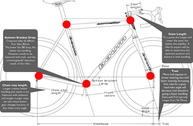
A bicycle comes in several different variations depending on the purpose of the ride. Different types among others are racer, downhill, cyklocross and classic. What is common for all thou is that they are composed of core points that have a connection to the different relations of the human body, connections that will enhance ergonomic aspects and make the ride more pleasant for the rider. These core points are marked out in the image below and further described.
Figure 2.14, The geometry of bike handling
2.2.1 Trail
The trail is a measured from the point where the front wheel comes in contact with the ground to the point where the front fork points to the ground. The elements affecting this distance are the angle of the fork and the front wheels offset from the steering axis.
When handling the bike, the trail affects the agility and stability of the bike. By decreasing the Trail, the rider achieves a greater agility which makes it easier to achieve sharp turns. The downside with a shorter trail is that the stability is lost at higher speed. The Trail is therefore depended on the nature of the bike. Common road bikes range from 40 to 55 mm trail, making them agile and easy to turn at low speeds while motorcycles usually have 80 mm trail to increase stability at high speed.
Fel! Hittar inte referenskälla. 2.2.2 Fork angle
The fork angle is as it says, the angle of the fork measured from the ground. The angle of the fork affects the stability of the ride. A shallow angle of the bike increases stability but can make the bike feel sluggish at low speed. A Steeper angle will make the bike quicker and more agile. The offset also affects these relations and a variety of forks can be bought with different offsets to tweak these relations.
2.2.3 Wheelbase and weight distribution
The wheelbase is the measurement from the center of the front and the back wheel. The wheelbase affects the stability of the bike. Depending on the positioning of the rider, this also affects the weight distribution. If the weight is distributed too much at the front, the rider will lose traction when pedaling. If the weight is distributed too much at the back, the rider will have problems keeping the fork down during steep climbs. Hence the recommended weight distribution is 45/55, meaning 45% of the collected mass of the rider and the bike should be focused on the front wheel and 55% should be focused on the rear wheel.
Once again, the weight distribution and the wheelbase differ depending on the nature of the bike. A wider wheelbase increases stability during high speeds, but at the same time it decreases the maneuverability.
2.2.4 Bottom bracket drop
The bottom bracket drop is measured from the wheel axis to the pedaling axis. Depending on this distance, the rider can increase maneuverability by placing the center of gravity closer to the ground. While this increases maneuverability, the pedaling clearance decreases. Depending on how much the rider will lean in to the curves, this distance needs to be tweaked in accordance to the way the bike will be ridden.
2.2.5 Chain stay length
The chain stay length is roughly distance measured from the pedaling axis to the back wheel axis. By having a short chain stay length, the rider increases the power transmission and the handling. The downside of having it short is that the chain crossover while riding on low gears will be greater and wear on the gears and the chain. By increasing the chain stay length, the rider can achieve greater comfort while riding but since the chain stay length increases, the frame will get longer which results in more weight.
Method
3 Method
This following chapter briefly describers the different methods that were used during the project.
3.1 Gantt schedule
The Gantt schedule were originally a production and control system, believed to originate from the beginning of the 20’th century. The purpose of the
schedule at that time were to overlook the number of products produces during a day and how they stood in accordance to the daily goal.
Nowadays it is referred to a project management tool that graphically places project goals in accordance to a time-axis. The project leader ends up with a graphical schedule, making it easier to overlook a project and its status. (Gantt.com)
3.2 Functional analysis
A functional analysis is a documentation of the functions of a product. By breaking down the functions, the designer defines the different problems that needs to be solved without stating how. The idea with defining functions in this way it to leave room for creative thinking and not thinking in terms of finished solutions.
The functional analysis is constructed by firstly defining the primary function of the product. For an example, the primary function for a coffee cup would be hold liquid. After defining the primary function, the functions necessary for the functionality of the product are defined, hence called necessary functions. For an example, necessary functions for the coffee cup would be apply lift, isolate heat, etc. Lastly the desirable functions are defined. The desirable functions are of such nature that they don’t affect the functionality of the product but could add interesting elements to the functionality or the form.
(Österlin, 2012)
3.3 Trend analysis
To launch a product, it is important that the product is developed in
accordance to the future trends. By doing a trend analysis, the designer can develop a concept that is tailored to the upcoming trends and meet the target consumer’s wishes and ideals, designing a product that is in time so to speak. A common way to analyze trends is to stay updated on what is produced on the market and what other major brands present on fairs and exhibitions. According to Österlin (2012), different industries discuss the future trends and agree on the general direction to pursue. Hence a trend becomes a mix of systematic research of the market and a self-fulfilling prophecy.
Method
3.4 PBS (Product breakdown structure)
A product breakdown structure is a document where a product is divided into its constituents. The main bodies of the product make the primary categories, these are then broken down into different sub-categories. Depending on the depth of knowledge the designer wants to achieve, the sub categories can go all the way down to the smallest components such as screws and bolts. Once the PBS is completed, it functions as a product mapping that provides the designer with a deeper understanding of the product and how the different components interact and function.
(productbreakdownstructure.com) 3.5 Competitor analysis
A competitor analysis is a research based on analyzing similar products from competing brands. By doing such an analysis, the designer can find
inspiration for the own product, avoid design issues, find solutions and make sure that the same function isn’t copied.
3.6 SWOT analysis
The word SWOT comes from Strengths, Weaknesses, Opportunities and Threats and is a tool to map the factors that could affect the project, bout internal and external.
The analysis is conducted by brainstorming different factors that can affect the project and writing them down into their designated area (see image below). One the chart has been filled out, conclusions can be made. The goal during this phase is to find gaps and common ground where different factors meet. These may later be utilized and open new ways and opportunities.
Method
3.7 Image board
An image board is collage of pictures that represent the feeling or image the designer wants to incorporate in his/her design. The image board is often constructed by first choosing lead words that are to be incorporated in the design, these are then expanded into synonyms to better understand the word. Once the words are established and a deeper understanding of the words are achieved, images, illustrations or photographs are collected. These images are to represent the words in the aspect of form, feeling and context and are used as a source of inspiration and reminder of the design goals during the entire project.
Other types if image board that are used is called personas. Personas are like image boards a collection of images that describer the personality of the user. This is used to by visual means understand the image of the target consumer. (Curedale, 2012)
3.8 Brainstorming
Brainstorming is a creative tool used to iterate ideas around a common problem. The ground principle is the more people that participate, the more associations and the more ideas the group come up with.
The conditions for a brainstorming session is that the group has to be defined with a designated moderator. The rules have to be defined and the sessions needs to be documented by a designated participant.
During the session it is also crucial that no criticism can occur which would suppress creativity and ruin the mood of the session.
There are a great variety of brainstorming versions that can be tailored to fit the problem, the group or the situation.
(Curedale, 2012) (Ullman, 2010)
3.9 Ideation and sketching
When ideating and coming up with new ideas for a project, sketching is a useful tool to communicate and visualize ideas to the client or the project participants. The advantages of dragging sketches of the intended product are that they can serve as an early underlay for evaluation. The different group members may have different expertise in their designated area, which makes it possible to eliminate errors early in the process. It is also possible to present physical- and 3d-models but they tend to be allot more time consuming.
Method
3.10 CAD-Modelling
Cad is short for Computer Aided Design and is a tool where the designer creates 3 dimensional models of his or her ideas. In early stages, the cad models serve as a source for evaluating the design and its geometric features. Later on thou, a more worked through model can serve as a tool for analyzing parameters that are interesting for functional reasons, such as impact
resistance or aerodynamics.
Depending on the model, there are different types of CAD-modelling, two examples would be solid modelling and surface modelling.
(Ullman, 2010)
3.11 Physical model
To better evaluate concepts during the design process, physical models can be produces. These models come in a great different variety depending on the purpose of the model. A mockup is a very simple version of a model where the general proportions usually are evaluated. These models can be built out of mostly anything, varying from paper models to lines of tape on the wall. The second type of models are presentation models. These models are built to look like the finished product but without any functionality.
The final type of models are prototypes, these models both look and function exactly like the finished product would. Many times, it is better to divide the models into one that is supposed to function as the finished product, and one that looks like the finished product. Depending on the model, these can also be built in different scales. It is preferred thou that models that are supposed have their functionality evaluated to be built in scale 1:1.
(Österlin, 2012)
3.12 Rapid prototyping
Rapid prototyping started 1986 when a company called 3D system of Valencia and was called Steriolithography (SLA). To create a rapid prototyping model through SLA, the designer start by creating a 3d model with a cad software. The cad model is then uploaded into the SLA-machine for printing. Printing through SLA works by having a laser track the model in a bath of a liquid polymer. When the polymer is struck by the laser it hardens into a solid plastic. While this produces high-end rapid prototyping models with a rather good surface finish, the models become rather expensive. Nowadays, more affordable machines are available for commercial use. An example of this is Makerbot.
Approach and implementation
4 Approach and implementation
4.1 Startup
4.1.1 Project description and Design brief
To start of the project and to make sure that the goals were clear to both Emtes engineering and the designer, a project description and a design brief was created.
The project description briefly describes the different methods that would be used during the project, goals and aims and a temporary time schedule that points out deadlines and important dates. The project description was made to make sure that both the clients and the student’s goals were fulfilled during the project.
The design brief was focused around the product and its environment. During the construction of the brief, Jens Bernsens template was used where the previously mentioned ten pointers were answered. The brief was constructed through discussions with Emtes engineering and by brainstorming ideas around the subject (See attachment 4 and 5).
Approach and implementation
4.1.2 Planning
The schedule was worked out in collaboration with the client and Berge consulting to make sure that no parts was neglected.
Important parts during the planning was to consider the end and intermediate results, the activities and important milestones. Once all the activities were considered, a GANTT schedule was composed that provided an overview of the entire project from start to end.
The model used during the planning phase was to use SMART planning. By smart planning the goals need to be Specific, Measurable, Acceptable, Realistic and in Time.
Approach and implementation
4.2 Empathize
4.2.1 Upcoming trends and future scenario
When looking at future trends and the development major cities there is a clear step towards a more environmental friendly approach to personal transportation. Larger car brands compete in increasing the efficiency of the combustion engine and many different design competitions circle around the eco-transportation subject. When asking Chris T. Hendrickson professor of civil and environmental engineering at Carnegie Mellon University about the upcoming trends in transportation, he said among other things:
“There is a new wave of interest in the concept of individualized small vehicles operating in a shared environment, especially for specialized environments (airports, theme parks, religious complexes, new green cities). “There have been such waves in the past,” notes Mahmassani. “Whether it takes hold this time depends on several factors that affect use and economics.” (Hendrickson C T, 2013)
Personal transit also includes biking and walking. “Expanding bike paths and trails, new urbanism development, and green buildings to encourage biking are all examples of engineering responses to traffic needs,” says
Hendrickson.” (Hendrickson C T, 2013)
Some major cities are currently struggling with air pollution. China for example has installed TV-screens that shows the population the sunrise and sunset because of the smog covering the sky. Paris has started a ban on driving your car on specific dates to decrease the traffic and exhaust. The only viable future is the end of the combustion engine and the development of green transportation. (Dailymail.co.uk, 2014)
Approach and implementation
4.2.2 Product/user analysis
The product-user analysis was carried out through interviews, discussion threads and by reading FAQ’s and forums that circled around bike and electric bike users to better understand the existing products, their needs and the experience. Questions during this session that was considered to carry weight was what elevated the experience of riding bikes and the values of the typical person that were affiliated with biking or had roots in motorsports.
The general feedback was that it was considered a bad idea to design a bike for downhill use with that many components on it. The experience of riding the bike was directly linked to the maneuverability and the weight. If the bike were to weigh around 30 kilograms, it was considered to be too heavy. A more viable approach would be to design a bike/motorcycle hybrid that would be lightweight and meant to drive on tracks or in the forest.
When looking at the placement of the engine there were really two
alternatives that existed on the market. The first alternative involved placing the engine inside the back-wheel, the second involved placing the engine close to the pedals.
When asking the target group what would be the best placement, the overall reaction was to have the engine fitted close to the pedals.
The reason was that when handling the bike, the rotation goes around and through the user. By placing the engine in the wheel you also increase the rotation of mass, making it harder to turn and handle the bike. There are also problems with undamped weight, which means that the wheel will have a harder time following the terrain. A way to solve the problem with undamped weight is to increase the stiffness of the suspension but by doing so, the user would upset the most optimal setting. In other words, the user solves a problem and create a new in the process.
The placement and type of engine was already stated in the delimitations but a study around the pros and cons was carried out nonetheless. One of the discoveries during this research was that few bikes have the engine fitted in the frame. The two most common solutions were either placing the engine in the wheel hub or simply attaching a standard engine to the frame. Hence the preferred solution would be integrating the engine in the frame for a uniform design.
Approach and implementation
4.3 Define
4.3.1 Rules and regulations
Before starting ideating for concepts, the laws and regulations for the vehicle had to be defined. If it can’t drive on Swedish roads, there isn’t really a point in making it to begin with. The main targets in this project are producing a
concept for the Swedish market, hence the rules and regulations had to be looked through.
4.3.1.1 Light motorcycle
Maximum velocity: Public road limits Driver’s license: Yes (A1)
License plate: Yes Drive on bike path: No Effect/weight ratio: 0.1
4.3.1.2 Medium motorcycle: Maximum velocity: Public road limits Driver’s license: Yes (A2)
License plate: Yes Drive on bike path: No Effect/weight ratio: 0.2
4.3.1.3 Moped class 1 Maximum velocity: 45 km/h Driver’s license: Yes (AM) License plate: Yes
Drive on bike path: No
4.3.1.4 Moped class 2 Maximum velocity: 25 km/h Driver’s license: no
License plate: No Drive on bike path: Yes
Approach and implementation
4.3.1.5 Bicycle Alternative 1
A vehicle that is driven by pedal or crank device and isn’t a toy vehicle
Alternative 2
An electric vehicle without pedals or crank device A: Deviced for single person transportation
B: Doesn’t exceed a maximum velocity of 20 km/h
Alternative 3
An electric vehicle with a pedal or crank device on the electric engine A: Only enhances the force from the pedals or crank device B: Doesn’t provide any force at a velocity above 25 km/h C: Has a net effect that doesn’t exceed 250w
(Notisum, Law on Road Traffic Definitions, 2014)
Concerning the possibility of driving in the forest, there is a law from 1975 that prohibit motorized vehicles. The aim is that the user can use the vehicle without a driver’s license or the most common AM/B license.
The maximum weight of the vehicle should be around 30 to 35 kilograms, making the power/weight ratio to be around 1,42-1.66. This makes it impossible to classify it as a light motorcycle.
With this as a background, the most attractive solution would be to offer two different moods on the vehicle. One where it is categorized as a bicycle with a help engine that doesn’t exceed 250w, making it possible to drive it in the forest. When the user wants to drive on designated tracks, the vehicle offers the entire 5 kW that the engine produces.
Approach and implementation
4.3.2 PBS (Product Breakdown Structure)
A product breakdown structure was conducted early in the project to
understand the product and all its components. The main bodied of the bike were divided into the groups frame, drive, steering and suspension. These groups were then expanded with their designated subgroups.
The depth of the PBS was designed to leave the small components such as screws and bolts out of the PBS since they were not considered to impact the overall understanding of the product.
Approach and implementation
4.3.3 Persona
By using the information from the target group analysis, a persona was constructed do identify the central image of the user, his/her interests and values. The persona functioned as a source of inspiration for the development of the concept.
The main target group is a male between 20-50 years old. He lives an active and adventurous lifestyle where nature plays a big part of his everyday life. His taste in music circles around rock and alternative music, bands that he favors are Millencollin, Muse and Foo Fighters. He is a problem solver that doesn't rely on the help of others to solve his problems, if a problem shows up, he fixes it himself. He enjoys riding a bike for two reasons. The first is because he is an adrenaline junkie, nothing makes his heart race the way riding a bike does. The second reason is that it activates his senses and sets him free from all thought. Riding the bike is the closest to meditating he gets.
Approach and implementation
4.3.4 Proportions
Early in the project, the proportions of the frame were discussed with Berge and Emtes engineering. The conclusion was to follow the proportions of a downhill bike, considering that the bike was to be driven off road. As a reference for the frame construction, the measurements for the bike brand Scott’s downhill frames were used.
Since the aim for the project was to design a vehicle designated for off road use but also public transportation, the proportions of an enduro motorcycles and downhill bike were studied. The study was carried out by observing the measurements of the “hardpoints” of the bike, how they differed compared to the motorcycle and how these relations affected the comfort of the bike. The hardpoints of the bike is where the frame tubes intersect, creating intersecting “hardpoints”.
Figure 4,5, Bike hardpoints
A deeper analysis around these measurements was not conducted
considering the limited time of the project, rather a general understanding was sought to grasp the effects of what would happen by changing them.
Approach and implementation
4.3.5 Bicycle VS Enduro motorcycle
The ideal would be to produce a vehicle with the advantages of both bicycle and an enduro motorcycle, hence the proportions of the two were studied in relation to one another. The greatest difference and challenge is the way the driver is seated on booth of the vehicles. On the bike the driver should be able to pedal with close to a straight leg, hence the seating must be adjustable to fit a variety of users. On an enduro motorcycle, the seat is stationary and the driver can be seated further in the front or the back. The purpose of this is to be able to shift the weight from the back wheel to the front depending on the terrain.
There is also no need to pedal on the motorcycle, hence the ability to shift height is neglected.
Approach and implementation
4.3.6 Market analysis
A market analysis was carried out to partially research the different solutions that existed on the market, but also to understand the public’s opinion about them. The market was divided into two different directions, the common pedelec and the more extreme products with stronger engines and larger battery packs.
The pedelec market has exploded during the last years which has led to that the larger bicycle manufacturers have or are developing pedelecs that fit in their product line. Among the products that were used as reference, the price ranged around 20-40 000 sek depending on the complexity of the bike. To be classified as a pedelec (as stated earlier in rules and regulations) the engine can’t exceed 250 watts and can only help the user apply force to the back wheel.
The bikes with larger engines and batteries are commonly seen as concepts from larger car brands where one of the most known comes from Audi. Other than these concept, the majority of the bikes are built by home enthusiasts. What most of the concepts have in common is the placement of the engine, which is stationed in the rear wheel. The batteries are commonly placed in the frame, between the driver’s legs. These bikes cost more than the traditional pedelec and range from around 50-70 000 sek.
Approach and implementation
4.3.7 SWOT
The SWOT analysis was conducted during a brief brainstorming session to identify the major points that would affect the vehicle. Considering the trend analysis and future scenario, it was considered that the products biggest strength would be an upcoming market. While the community is getting more and more environmental friendly, it was considered that the market for green transportation will grow in the future.
The biggest weakness of the product was considered to be the price. The aim for the product was to produce a product that would cost around 50 000 sek. Looking at the market analysis, a pattern can be found where the majority of these vehicles cost around that amount. While enthusiasts can agree to pay even more for a high-quality product when it comes to biking, the majority may agree on that the price is too high and would buy a regular motorcycle
instead.
The biggest opportunity for the vehicle would be the development of new power sources. Fuel cells are under development and are expected to be available in the near future. These could revolutionize the market where the efficiency rate goes up to 85% and can be recharged by simply filling it up with hydrogen. However, the biggest threat is simply the rules and regulations.
Approach and implementation
4.3.8 Image board
The image board were constructed by first selecting three value words that would represent the feelings the form language of the product would express. The words chosen were speed, robustness and ferocious/aggressive. The word speed was chosen simply because speed and acceleration would be an element that defined the product. Robustness was chosen in accordance to the user research. The user wanted something that lasts and withstands impacts, hence the product needed to look robust. The word ferocious was a challenging and an intriguing element to the form. Early in the project, there was an idea to design using elements from nature. In this case, the inspiration was taken from the family of feline.
Approach and implementation
4.3.9 Form study
The form study was conducted by analyzing form and trying to grasp an understanding of why the form of the objects reflect different sensations. In this case, the words chosen for the image board was analyzed by searching the web to collect different objects or products that matched the words.
Speed
By searching with the value word speed, the top hits often resulted in cars, motorcycles and boats. Vehicles that are built for great speed and to accelerate seemed to have a common denominator. They were all aerodynamically optimized.
Our understanding of something that is built for speed seem to circle around the form of aerodynamics. While the most aerodynamic form can be found in nature as the water droplet, the man-made form that incorporates speed are often sleek surfaces where the dominant form aligns with the stopping force of nature.
Some good examples where speed is incorporated in the form language can be found in the jet fighters, bullet trains and sports cars.
Approach and implementation
Robustness
The search results for robustness was insignificant, hence the word was broken down into what was considered to incorporate robustness. The words used was among others impact resistant, solid, durable and resistant. The search resulted in heavy, large and hard objects that were reinforced in some ways.
The understanding of robustness was therefor considered to be strongly connected to the material properties, reinforcements and the stability of the object.
Reinforced could be considered to be the fact that the object lacked sharp corners or had them covered with a softer material. By making the object heavy it would seem less likely to fall over or tilt, hence reflecting a feeling of security.
The robustness of the material was considered to be linked to scratching the surface. A high gloss surface would seem more likely to scratch rather than a matt or low reflective surface.
Some good examples where robustness is incorporated in the form language can be found in impact resistant phones, protective gear and off-road cars.
Approach and implementation
Ferocity/aggressive
The search results for ferocity resulted in different pictures from the animal kingdom such as lions, wolfs and tigers.
The search was considered to be inconclusive, hence the word was analyzed to understand what made something look ferocious. The lead word that was picked for this purpose was aggressive.
When looking at different car concepts, some brands try to incorporate the form of animals into their cars. The aggressive elements can often be seen here in the form of the headlight, grill and direction of the car. To better understand the impact of these elements and how they expressed aggressiveness, different cars were analyzed.
When listening to car designer and visual artist Daniel Simon, the aggressive elements of car design is strongly related to the way humans express anger or aggression. When designing neutral elements, the face of the vehicle often consists of horizontal or vertical lines. The direction of these lines doesn’t suggest any particular emotion and reflect a neutral statement.
When designing aggressive elements on the other hand, the lines often angle downwards. This can be seen on the headlights of most cars. The form of the cars can also be compared to a pouncing animal where the shoulder of the back wheel is higher than the front, giving it a strong direction forward. (Simons D, 2014)
Approach and implementation
4.3.10 Functional analysis
To identify the functions of the pedelecs, a functional analysis was formulated for the target consumer and the vehicle. Like mentioned earlier, the analysis focused on things that needed to be solved that were found during the analysis but not how they were to be solved. The analysis was later used during the ideation process to stimulate creative thinking but also to as a check-list to see that functions hadn’t been neglected.
P - Primary function N - Necessary function D - Desired function
P Allow Transportation User
N Allow Adjustment Saddle, steering
N Provide Protection User
N Allow Recharge Energy source
N Facilitate Transportation Vehicle and user
N Communicate Value Company & product
N Be Water resistant Vehicle
N Allow Storage Vehicle
D Facilitate Maintenance Vehicle
D Facilitate Repair Vehicle
D Communicate Information User
D Offer Comfort User
Approach and implementation
4.4 Ideation 4.4.1 Morphology
To explore some different variations of the different shapes and forms of the frame, a morphology was conducted with the hard points as a reference. The focus of the morphology was to explore as many different shapes as possible and reflect on what expression they invoked.
Approach and implementation
4.4.2 Ideation 1
The ideation phase started in the beginning of the project and proceeded through the entire project. The first phase focused around exploring the proportions and different forms of the vehicle to better understand the
limitations of the design. Functions such as the placement of the engine and the battery proved to be the biggest issue, both function- and form-wise during this phase.
It was concluded during the ideation that the battery and engine would control the limitations of the frame, hence the placement of these components
became the focus during the ideation phase.
This exploration phase was first and foremost explored with simple
perspective drawings, side views and silhouettes to express the direction and aggressiveness of the bike.
Approach and implementation
4.4.3 Evaluation 1
After the first ideation phase, the different concepts were evaluated with Berge and Emtes to decide the general direction the next ideation phase would go in. The evaluation was carried out by discussing the research that had been carried out at this point and
4.4.4 Ideation 2
The second ideation phase focused on more detailed line drawings in side view and in perspective. This phase proceeded during a longer time and was treated as an iterative process, exploring different configurations and forms to return to the main ideas for more inspiration. The image below shows a few of the sketches and main ideas that were explored and how the ideation phase was carried out.
Approach and implementation
4.4.5 Ideation 3
During the third ideation phase, the most interesting forms were explored further. This phase circled around three concepts with different solutions for the battery and engine placement. These were later presented on the mid presentation for evaluation.
Concept 1
Concept one was designer by angling the top and bottom tube parallel to each other with a slight upward direction, giving the frame an upward direction expressing the urge to climb.
This concept also experimented with a split fork tube. The idea was to give the vehicle a face with an aggressive expression. The original idea was to
integrate lights in the split to enhance this sensation but considering that the light would have to follow the direction of the wheel, this idea was neglected.
Approach and implementation
Configuration 1
Concept 1 has got the battery pack placed in the free space of the frame, between the legs of the rider. The engine and planetary gear is snugly fitted close to the pedals, giving them a low center of gravity. The force is
transmitted from the pedals to a straight sequential gearbox fitted above the pedals.
Approach and implementation
Concept 2
The second concept uses the seat post as battery to make the vehicle look more agile and to relieve the frame from a “bulky” and heavy look. By angling the top tube in an almost horizontal direction, the bike expresses a very strong direction forward and downward. This in turn gave the bike a sensation of speed and the hollow space between the frame tubes acted as a muscle, expressing power.
Approach and implementation
Configuration 2
The Engine is placed close to the pedals and is connected to the planetary gearbox, giving them a low center of gravity. The battery-pack consists of six battery cells that are connected two by two and in series to provide the engine with power. The power is transferred from the engine to the back wheel by a standard chain and changes the ratio with traditional bike gears
Approach and implementation
Concept 3
The final concept took inspiration from triangular shapes and an upward direction of the frame. The main idea was to design the frames with the negative areas of swing and the main frame by mirroring a triangle against each other to unify the form language of the swing and the main frame.
The fork tube was also split in concept to play around with the aggressiveness of the “head”. The big difference here on the other hand was a narrower split and with an edgier look, making it look even more intense.
Approach and implementation
Configuration 3
The big difference with concept three was the battery configuration. The frame would hold two battery cells that would act as a power supply for the engine to help the driver during climbs. The driver would then use a backpack that also acts as a back protection for a more aggressive driving style, either on main roads or of road.
The idea with this configuration was to increase the agility and handling of the bike decreasing the rotation of mass by moving the batteries to the backpack and by placing the engine below the driver, decreasing the rotation of mass. This would also allow more freedom when designing the form of the bike. The engine is fitted in connection to the planetary gear and the pedals with a low center of gravity and the force is transferred from the pedals to a straight sequential gearbox inside the back wheel.
Approach and implementation
4.5 Prototype/Testing
To help evaluate the three different concepts, a simulation was carried out. The idea with the simulation was to attach weights to a mountain bike that would have the same configuration as the three concepts.
4.5.1 Configuration 1
The first simulation was configured the same way as concept one. Four kilograms were fitted to the frame to simulate the planetary gearbox, the
engine and the battery cells. The center of gravity was focused in the center of the frame and as close to the pedals as possible.
Figure 4,23, Testing configuration 1
The simulation proved that the maneuverability of the bike decreased with the weights attached. The ability of lifting the front wheel from the ground and turning were decreased and the bike simply felt clumsier.
The weights also made climbing steep hills harder which were strongly related to the overall weight of the bike and the ability to pedal while standing.
Approach and implementation
4.5.2 Configuration 2
The second simulation was configured to simulate concept two with the mass centered around the saddle post and middle of the frame. Six kilograms in this case were fitted close to the saddle post to move the center of mass aligned with the pedals and the saddle post.
Figure 4,24, Testing configuration 2
The sensation of this configuration was the same as during the first simulation but with even less agility during handling. Climbing with the bike was made even harder with more mass to handle while pedaling in a standing position and with more weight to the bike.
Approach and implementation
4.5.3 Configuration 3
The final simulation was configured to simulate concept three. Two kilograms were fitted close to the pedals to simulate the engine and the planetary
gearbox and two kilograms were placed in a backpack to simulate the battery pack.
Figure 4,25, Testing configuration 3
The maneuverability of the bike was increased by decreasing the weights to the frame which was expected. What wasn't expected was how little the weights in the backpack affected the ride. The backpack didn’t affect the agility of the bike nor made a big difference during climbs. Instead of
transporting the mass of the bike, the increased mass of the backpack could be applied on the pedals.