Civil Engineering Journal
Vol. 5, No. 11, November, 2019Study Numerical Simulation of Stress-Strain Behavior of Reinforced
Concrete Bar in Soil using Theoretical Models
Ali Sabah Al Amli
a, b*, Nadhir Al-Ansari
b, Jan Laue
ba Al-Mustansiriyah University, Palestine Street, 10052 Baghdad, Iraq. b Lulea University of Technology, 971 87 Lulea, Sweden.
Received 07 May 2019; Accepted 19 August 2019
Abstract
Nonlinear analysis for reinforced concrete members (R.C.) with two types of bars also with unsaturated and saturated soils was used to represent the models. To control the corrosion in the steel bar that used in R.C. member and decrease the cost, the geogrid with steel bar reinforcement are taken in this study to determine the effect of load-deflection and stress-strain relationships.The finite element method is used to model the R.C. member, bars and soil. A three-dimensional finite element model by ABAQUS version 6.9 software program is used to predict the load versus deflection and stress versus strain response with soil. The results for the model in this study are compared with the experimental results from other research, and the results are very good. Therefore, it was concluded that the models developed in this study can accurately capture the behavior and predict the load-carrying capacity of such R.C. members with soil and the maximum stresses with strains. The results show plastic strain values in the R.C. member with saturated soil are larger than their values in unsaturated soil about (54%, 58%, and 55% and 52%) when the geogrid ratios are (without geogrid, 60%, 40% and 20%) respectively, with the same values of stresses.
Keywords: Numerical; Reinforced; Concrete; Bar; Geogrid; Saturated Soil; Models; Stress; Strain; Method; Analysis.
1. Introduction
The effect of Soil-structure interaction between soil and member for any structures is very interesting and important field of study in civil engineering. Reinforced concrete member as a structure is the most important part of whole structures and their behavior has an important effect on quality of buildings. Member can influence of many parameters in the building. For the best design it is necessary to known behavior of the reinforced concrete member with the soil [1- 4].
Modern reinforced concrete R.C. members are used to develop deformations in their regions [5]. The occurrence of longitudinal bar regions can crucially affect the behavior of such members. This study extends a previously proposed modeling approach for R.C. bar elements whose response is affected by R.C. member with soil. The model is representing to steel and geogrid bars as a reinforcement.
The geogrid have advantage for its strength as reinforcement in reinforced concrete member [6] .This geogrid used in the soil- structure members to treat corrosion and its shape gives it more bonds with concrete. Therefore, this geogrid is useful in structures that have contact with soil or saturated soil which may be contents many types of liquids where it represents bars reinforcement for this structure like any member with soil.
* Corresponding author: ali.sabah@ltu.se
http://dx.doi.org/10.28991/cej-2019-03091416
© 2019 by the authors. Licensee C.E.J, Tehran, Iran. This article is an open access article distributed under the terms and conditions of the Creative Commons Attribution (CC-BY) license (http://creativecommons.org/licenses/by/4.0/).
Geosynthetics are widely used for separation, protection, drainage, filtration and sealing [7]. In addition, high-strength geogrids have been more successfully used in geogrid reinforced bridge. Geogrid reinforcement constructions show significant advantages in terms of economic aspects against classical concrete structures. It is also well known from large-scale experiments and field tests that geosynthetic-reinforced constructions have a much higher bearing capacity than calculated and that the deformations are much lower than expected. Therefore, it is quite evident that the compound behavior of geosynthetic and soil is not yet completely understood [7].
Geosynthetics have been increasingly used as reinforcing construction material. Many projects such as roads, retaining walls, etc. Many types of products (geogrid, geotextile, geocell, geomebrane, etc.) are available in engineering process .Each product is designed to solve a particular range of civil engineering problems [8-12].
The developed Finite Element (F.E.) models account for R.C. structures behavior was concluded that the developed models can accurately capture the behavior and predicts the load –carrying capacity of R.C. members [13-16]. There are several software, theoretical and experimental methods deal with R.C. member [17-24]
To control the corrosion effect for the steel bar reinforcement in the R.C. member, need the another type of reinforcement. This type must be with less cost and gives the required capacity to the member. Therefore, the geogrid have been used in this study to find the behavior of member with two types of reinforcement, and study the different ratios of geogrid with steel reinforcement. Also, the behavior of R.C. member with this reinforcement when taken with soil, it gives a best conception of the designer. In this research many types of bars are used: steel bar and geogrid reinforcement with R.C. member in saturated and unsaturated soils.The commercial finite element software ABAQUS was used to develop finite element model capable of simulating the effect of reinforcing bars in reinforced concrete member with soils. This study used interaction properties in the present model with two kinds of bars and soils to get the stress-strain relation for reinforced concrete member. The stress-strain relations are studying for different ratios of bar reinforcement (steel and geogrid bars) .All these parameters studied with the effect of unsaturated and saturated soil. This study is very important to control for corrosion and to increase the capacity and strength of foundation when know the behavior of R.C. bars in saturated and unsaturated soils.
2. Finite Element Modeling
This study used the reinforced concrete (R.C.) member with unsaturated and saturated soil with two kinds of bars (Steel bars and geogrid) are used as reinforcement. This R.C. member with soil is modeled and represented as follow:
2.1. Elements
Full modeling of member, soil, reinforcing elements and loading are performed using finite element method package ABAQUS. The interaction between the member and the soil in the vertical direction is normal hard contact, without penetration, while in the other direction is tangential behavior. The interaction between the member and the reinforcement (steel bar and geogrid) is embedded.
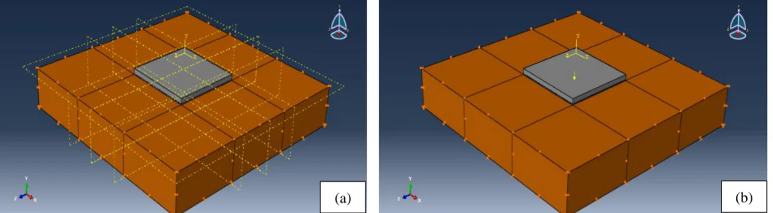
R.C. foundations with saturated and unsaturated soils and using steel bar and geogrid reinforcement are represented in the models shown in Fig.1 by the following elements:
Member with Soil, 8-node linear brick, reduced integration element (linear brick);
Steel Reinforcement, 2-node linear 3-D truss element (truss element);
Geogrid, 4-node quadrilateral surface element (node elements).
Figure 1. Finite Element Models: (a) Member Model; (b) Member with Steel and Geogrid reinforcement; (c) Interaction and Load Area Model
2.2. Plastic Models
The plastic analysis for the present model is divided as:
Member: Concrete damage plasticity;
Soil: Mohr-coulomb plasticity;
Bar reinforcement (steel and geogrid): Classic metal plasticity. 2.3. Reinforcement Model
The simulation for steel and geogrid bars as follow:
The steel bars were simulated as a multiple trusses embedded inside the concrete;
The Geogrid was simulated as a surface embedded inside the concrete (the surface was modeled with a rebar option which can simulate the actual geogrid properties).
2.4. Boundary Condition
The modeled boundary conditions are assumed that the vertical boundaries are free vertically, and the load applied at the load area as shown in Figure 2.
Figure 2. Boundary Condition: (z) Member; (b) Member and Loading
3. Material Model
The dimensions of member are 2×2 m with 0.15 m thickness and with 0.4×0.4 m area for applied load. The numerical simulations for behavior R.C. bars for two types of reinforcement (steel and geogrid reinforcement) with unsaturated and saturated soil using finite element models by ABAQUS software program are used. The properties for concrete which has a compressive strength fc´ and young’s modulus of elasticity E are 35MPa and 24000MPa respectively. The properties of soil, steel and geogrid reinforcement are shown as follow:
3.1. Soil Constitutive Law
This elasto-plastic model requires the parameters shown in Table 1. (c)
Table 1. Soil Parameters
Soil Parameter Unsaturated Saturated
Young’s modulus (E) 50 MPa 40MPa Poisson ratio (v) 0.3 0.49
Cohesion (c) 90 KPa 50 KPa Friction angle (ɸ°) 20° 0 Dilatancy angle (Ψ°) 0 0
3.2. Steel Model
The steel bar was modeled using elasto-plastic constitutive model with the parameters shown in Table 2.
Table 2. Steel bars parameters
Young’s modulus (E) Poisson ratio (v) Yield stress (fy)
200000 MPa 0.3 420 MPa
3.3. Geogrid Model
The geogrid was modeled using elasto-plastic constitutive model with the parameters shown in Table 3.
Table 3. Geogrid parameters
Young’s modulus (E) Poisson ratio (v) Bearing Strength
67000 MPa 0.2 100 KN/m
4. Results and Discussion
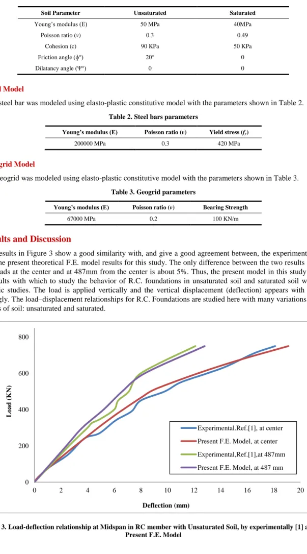
The results in Figure 3 show a good similarity with, and give a good agreement between, the experimental results [1] and the present theoretical F.E. model results for this study. The only difference between the two results is for the failure loads at the center and at 487mm from the center is about 5%. Thus, the present model in this study can give good results with which to study the behavior of R.C. foundations in unsaturated soil and saturated soil with many parametric studies. The load is applied vertically and the vertical displacement (deflection) appears with this load accordingly. The load–displacement relationships for R.C. Foundations are studied here with many variations and with two types of soil: unsaturated and saturated.
Figure 3. Load-deflection relationship at Midspan in RC member with Unsaturated Soil, by experimentally [1] and the Present F.E. Model
0 200 400 600 800 0 2 4 6 8 10 12 14 16 18 20 Lo a d (K N) Deflection (mm) Experimental.Ref.[1], at center Present F.E. Model, at center Experimental,Ref.[1],at 487mm Present F.E. Model, at 487 mm
4.1. Reinforced Concrete Member with Unsaturated Soil
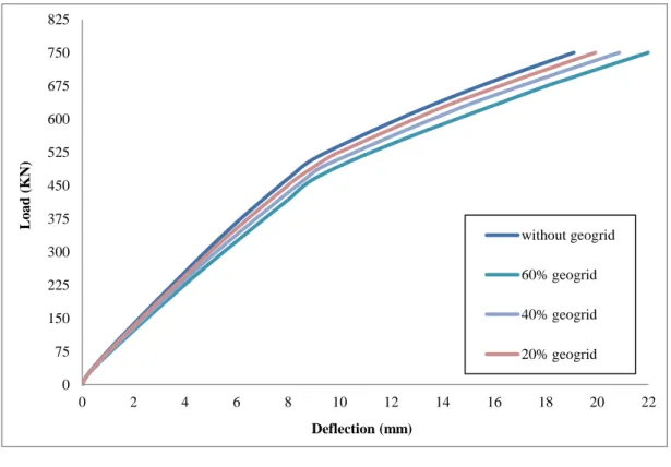
In this study, two types of reinforcement bar are taken for R.C. member (foundation) with soil, a steel bar and geogrid reinforcement. Figure 4 shows the load-deflection relationship for a R.C. member with unsaturated soil. The results in Figure 4 show that, When the geogrid ratios become (60, 40 and 20%), the deflection increases by about (13.135, 8.47 and 4.207%), respectively, compared to the situation without geogrid (steel reinforcement only).The results show that the geogrid ratio is very important to satisfy the required capacity for the R.C. member. When the geogrid ratio becomes zero (without geogrid), the steel bars reinforcement give the required strength capacity for R.C. member. Also, when the geogrid ratio used with suitable ratio near to 20%, the R.C. member gives good strength capacity. When the geogrid ratio increased to more than 20%, the strength capacity decreased. This behavior for R.C. member as a result for the same failure load (ultimate load) with difference values of deflection, where the ratio of reinforcement which gives the less deflection in R.C. member, is taken as the best reinforcement.
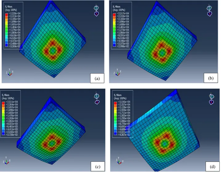
The stress-strain relationship for R.C. member with steel bar reinforcement and difference ratios of geogrid in unsaturated soil is shown in Figure 5; the results show the plastic strain with maximum stress. When the geogrid ratios become (60, 40 and 20%), the plastic strains increase about (3.7, 2.6 and 1.3%) respectively, compared to the situation without geogrid (steel reinforcement only). The behavior of R.C. member with effects of stresses shows that the R.C. member without geogrid and with steel reinforcement only, gives the higher strength than, when the geogrid used. When the stress increased the strain increased, but the values of strains for R.C. member without geogrid give smaller values of strain compared with the other ratios of reinforcement when geogrid is used. When the stresses arrive to the plastic stage, the behavior of R.C. member with all reinforcement ratios gives the same behavior. Thus, the maximum stresses with plastic strain in horizontal direction effected at the member when in elastic stage, and don’t effected in the plastic stage, therefore, the R.C. members give the same behavior with very small difference even if the ratio of reinforcement are different. Figure 6 shows the stresses distribution at the end of R.C. members with different ratios of steel bar and geogrid reinforcement with unsaturated soil.
Figure 4. Load –deflection Relationship for R.C. member with steel bar and difference geogrid ratios in unsaturated soil
0 75 150 225 300 375 450 525 600 675 750 825 0 2 4 6 8 10 12 14 16 18 20 22 Lo a d (K N) Deflection (mm) without geogrid 60% geogrid 40% geogrid 20% geogrid
Figure 5. Stress-strain Relationship in R.C. member Model in (Unsaturated Soil) with Steel Bar Reinforcement and Different Ratios of Geogrid in unsaturated soil
Figure 6. Stresses distribution in RC member with steel bar reinforcement and difference ratios of Geogrid in unsaturated soil: (a) geogrid 20%; (b) geogrid 40%; (c) geogrid 60%; (d) without geogrid
4.2. Reinforced Concrete Member with Saturated Soil
Two types of reinforcement bar are taken for RC member (foundation) with soil, a steel bar and geogrid reinforcement. Figure 7 shows the load-deflection relationship for a R.C. member with unsaturated soil. The results
0 5000 10000 15000 20000 25000 30000 35000 0 0.001 0.002 0.003 0.004 0.005 0.006 0.007 0.008 S tr ess (K Pa ) Strain without geogrid 60% geogrid 40% geogrid 20% geogrid (a) (b) (c) (d)
shown that, When the geogrid ratios become(60, 40 and 20%), the vertical displacement increases by about (25, 17.7 and 9.5%), respectively, compared to a situation without a geogrid (steel reinforcement only). The behavior of R.C. member in saturated soil with difference ratios of geogrid and steel reinforcement shows that, when increased the geogrid ratio, the deflection increased, and the values of deflection in R.C. member with saturated soil are larger than their values when the soil is unsaturated. As a result of this behavior, the saturated soil decreased the strength capacity for R.C. member by increased the deflections.
The stress-strain relationship for R.C. member with steel bar reinforcement and difference ratios of geogrid in saturated soil is shown in Figure 8; the results show the plastic strain with maximum stress. When the geogrid ratios become (60, 40 and 20%), the plastic strains increase about (2, 1 and 0.8 %) respectively, compared to the situation without geogrid (steel reinforcement only). The behavior of R.C. member with difference ratios of reinforcement shows that, the geogrid ratios increased the strains, but these strains values become very close at the plastic stage and give the same behavior for stress-strain relationship. The effect of saturated soil gives the R.C. member smaller capacity than unsaturated soil. Since, this member carries the ultimate stresses smaller than their values in unsaturated soil. This means that, the R.C. member in saturated soil becomes less capacity to carry the stresses. Figure 9 shows the stresses distribution at the end of R.C. members with different ratios of steel bar and geogrid reinforcement with saturated soil.
Figure 7. Load –deflection Relationship for R.C. member with steel bar and difference geogrid ratios in saturated soil
Figure 8. Stress-strain Relationship in R.C. member Model in (Saturated Soil) with Steel Bar Reinforcement and Difference Ratios of Geogrid 0 75 150 225 300 375 450 525 600 675 0 10 20 30 40 50 60 70 80 Lo a d (K N) Deflection (mm) without geogrid 60% geogrid 40% geogrid 20% geogrid 0 5000 10000 15000 20000 25000 30000 0 0.001 0.002 0.003 0.004 0.005 0.006 0.007 S tr ess (K Pa ) Strain without geogrid 60% geogrid 40% geogrid 20% geogrid
Figure 9. Stresses distribution in R.C. member with steel bar reinforcement, and difference ratios of Geogrid in saturated soil: (a) geogrid 20%; (b) geogrid 40%; (c) geogrid 60%; (d) without geogrid
5. Conclusions
The present model can represent the R.C. member with unsaturated and saturated soil, and with many kinds of reinforcement bars like steel and geogrid reinforcement.
The plastic strain values in the R.C. member with saturated soil are larger than their values in unsaturated soil about (54, 58, and 55 and 52%) for geogrid ratios (without geogrid, 60, 40 and 20%) respectively with the same values of stresses. Thus, the unsaturated soil gives less strength to the R.C. member.
The stresses with strains at the plastic stage are in the horizontal direction for the R.C. member.
The ultimate load for R.C. member without geogrid reinforcement in unsaturated soil is larger than its value when in saturated soil by 16%.Thus, the R.C. member with saturated soil is less strength capacity than when it is with unsaturated soil.6. Conflicts of Interest
The authors declare no conflict of interest.
7. References
[1] Buchta, Vojtech, Martina Janulikova, and Roman Fojtik. “Experimental Tests of Reinforced Concrete Foundation Slab.” Procedia Engineering 114 (2015): 530–537. doi:10.1016/j.proeng.2015.08.102.
[2] Elsaigh, W., and E. P. Kearsley. "Effect of ductility on load-carrying capacity of steel fibre reinforced concrete ground slabs." Journal of the South African Institution of Civil Engineering= Joernaal van die Suid-Afrikaanse Instituut van Siviele Ingenieurswese 45, no. 1 (2003): 25-30.
(a) (b)
[3] Alani, Amir M., Joseph Rizzuto, Derrick Beckett, and Morteza Aboutalebi. “Structural Behaviour and Deformation Patterns in Loaded Plain Concrete Ground-Supported Slabs.” Structural Concrete 15, no. 1 (March 2014): 81–93. doi:10.1002/suco.201300043.
[4] Tiberti, Giuseppe, Fausto Minelli, and Giovanni Plizzari. “Cracking Behavior in Reinforced Concrete Members with Steel Fibers: A Comprehensive Experimental Study.” Cement and Concrete Research 68 (February 2015): 24–34. doi:10.1016/j.cemconres.2014.10.011.
[5] Sadik Can Girgin, Ioannis Koutromanos, and Mohammadreza Moharrami.” Numerical simulation of reinforced concrete members with reinforcing bar buckling.” 12th International Congress on Advances in Civil Engineering.
[6] Ahmed, Ali S., Yousif, Mustafa A. and muhammed, Mahmood H.”Reinforced concrete strengthening by using geotextile reinforcement for foundations and slabs.” International Journal of Civil, Structural, Environmental and Infrastructure Engineering, Research and Development 7 (June 2017): 35-46.
[7] Ziegler, Martin. “Application of Geogrid Reinforced Constructions: History, Recent and Future Developments.” Procedia Engineering 172 (2017): 42–51. doi:10.1016/j.proeng.2017.02.015.
[8] Sharma, Radhey, Qiming Chen, Murad Abu-Farsakh, and Sungmin Yoon. “Analytical Modeling of Geogrid Reinforced Soil Foundation.” Geotextiles and Geomembranes 27, no. 1 (February 2009): 63–72. doi:10.1016/j.geotexmem.2008.07.002. [9] Kolay, P. K., S. Kumar, and D. Tiwari. “Improvement of Bearing Capacity of Shallow Foundation on Geogrid Reinforced Silty
Clay and Sand.” Journal of Construction Engineering 2013 (2013): 1–10. doi:10.1155/2013/293809.
[10] Vashi, Riddhi, Amit Patel, and Krunali Patel. “A Parametric Study on Behaviour of Geogrid Reinforced Earth Retaining Wall”, International Conference on Research and Innovations in Science, Engineering & Technology, Gujarat, India (February 2017). doi:10.29007/9x4z.
[11] Xiao-Song, T. A. N. G., Ying-Ren ZHENG, and W. A. N. G. Yong-Fu. "Application and Analysis of the Reinforced Retaining Wall with Geo-grid." In 2014 International Conference on Mechanics and Civil Engineering (ICMCE-14). Atlantis Press, 2014. [12] Bolt, ADAM F., and A. Duszynska. "Pull-out testing of geogrid reinforcements." In 2nd European Conference on Geosynthetics,
Bologna, Italy. 2000.
[13] Hawileh, R.A. “Finite Element Modeling of Reinforced Concrete Beams with a Hybrid Combination of Steel and Aramid Reinforcement.” Materials & Design (1980-2015) 65 (January 2015): 831–839. doi:10.1016/j.matdes.2014.10.004.
[14] Nam, Sang-Hyeok, Ha-Won Song, Keun-Joo Byun, and Koichi Maekawa. “Seismic Analysis of Underground Reinforced Concrete Structures Considering Elasto-Plastic Interface Element with Thickness.” Engineering Structures 28, no. 8 (July 2006): 1122–1131. doi:10.1016/j.engstruct.2005.12.003.
[15] Delalibera, R. G., and J. S. Giongo. “Theoretical and Numerical Analysis of Reinforced Concrete Beams with Confinement Reinforcement.” Revista IBRACON de Estruturas e Materiais 1, no. 1 (March 2008): 17–30. doi:10.1590/s1983-41952008000100002.
[16] Ahmed, Ali Sabah. "Behavior of Repaired Composite Modified Reactive Powder Concrete I-Section Beams With Opening under Pure Torque." Journal of Engineering and Sustainable Development 21, no. 1 (2017): 39-50.
[17] Cajka, Radim, Jana Labudkova, and Petr Mynarcik. "Numerical solution of soil-foundation interaction and comparison of results with experimental measurements." International Journal of GEOMATE 11, no. 1 (July 2016): 2116-2122. doi:10.21660/2016.23.1208.
[18] Bolisetti, Chandrakanth, Andrew S. Whittaker, and Justin L. Coleman. “Linear and Nonlinear Soil-Structure Interaction Analysis of Buildings and Safety-Related Nuclear Structures.” Soil Dynamics and Earthquake Engineering 107 (April 2018): 218–233. doi:10.1016/j.soildyn.2018.01.026.
[19] Durante, Maria Giovanna, Luigi Di Sarno, and Armando Lucio Simonelli. “Numerical Simulation of Soil-Structure Interaction: A Parametric Study.” Proceedings of the 6th International Conference on Computational Methods in Structural Dynamics and Earthquake Engineering (COMPDYN 2015) (2017). doi:10.7712/120117.5666.18467.
[20] Stefanidou, Sotiria P., Anastasios G. Sextos, Anastasios N. Kotsoglou, Nikolaos Lesgidis, and Andreas J. Kappos. “Soil-Structure Interaction Effects in Analysis of Seismic Fragility of Bridges Using an Intensity-Based Ground Motion Selection Procedure.” Engineering Structures 151 (November 2017): 366–380. doi:10.1016/j.engstruct.2017.08.033.
[21] Zhan, Yijian, and Günther Meschke. “Adaptive Crack Modeling with Interface Solid Elements for Plain and Fiber Reinforced Concrete Structures.” Materials 10, no. 7 (July 8, 2017): 771. doi:10.3390/ma10070771.
[22] Vrána, Radek, Ondřej Červinek, Pavel Maňas, Daniel Koutný, and David Paloušek. “Dynamic Loading of Lattice Structure Made by Selective Laser Melting-Numerical Model with Substitution of Geometrical Imperfections.” Materials 11, no. 11 (October 29, 2018): 2129. doi:10.3390/ma11112129.
[23] Vogel, Hans-Jörg, Stephan Bartke, Katrin Daedlow, Katharina Helming, Ingrid Kögel-Knabner, Birgit Lang, Eva Rabot, et al. “A Systemic Approach for Modeling Soil Functions.” SOIL 4, no. 1 (March 15, 2018): 83–92. doi:10.5194/soil-4-83-2018. [24] Montava, Isaac, Ramon Irles, Jorge Segura, Jose Gadea, and Ernesto Juliá. “Numerical Simulation of Steel Reinforced Concrete