An Approach to Multi-Disciplinary
Aero Engine Conceptual Design
Konstantinos G. Kyprianidis konstantinos.kyprianidis@mdh.se
M ¨alardalen University Future Energy Center V ¨asterås
Sweden
ABSTRACT
Various aspects of a multi-disciplinary aero engine conceptual design approach and compu-tational framework are presented. The approach closely integrates different disciplines and is capable of homing in on the best designs in the presence of techno-economic and environ-mental risk. The framework can assist in the transition from the traditional, human-centered design procedure that involves complex manual iterations, to a more automated process. It considers the following disciplines: engine performance, engine aerodynamic and mechani-cal design, aircraft design and aerodynamic performance, emissions prediction and environ-mental impact, engine and airframe noise, and production, maintenance and direct operating costs. The proposed explicit conceptual design algorithm reduces system complexity, im-proves computational speed and can make design space exploration and optimisation results easier to interpret. Through a good set of constraints, it will also give an optimal aero engine conceptual design that may prove feasible in terms of major engine certification and customer requirements. The power of the proposed conceptual design approach has been demonstrated through a variety of unique case studies. These range from technology assessment and design sensitivity analysis to design space exploration and optimization. Overall, the work sets the necessary base for an assessment methodology that can quantify risks and assess the impact of gas turbine design on the environment, by comparing and helping to rank future technologies and design concepts for civil aviation on a formal and consistent basis.
Keywords: Conceptual Design; Engine Performance; System Analysis. ISABE 2017
NOMENCLATURE
A18 bypass nozzle geometric area [m2] A8 core nozzle geometric area [m2] Alt flight altitude [m]
BPR bypass ratio [-]
dP26Q25 intercooler hot stream fractional pressure loss [-] dP308Q307 recuperator cold stream fractional pressure loss [-] DpNOx/Foo NOxcertification parameter [g/kN]
EPNL effective perceived noise level [dB] ETA13 fan bypass isentropic efficiency [-] ETA23 fan core isentropic efficiency [-]
ETA25 intermediate pressure compressor isentropic efficiency [-] FN net thrust [kN]
FL flight level [100ft]
M Mach number [-]
OPR overall pressure ratio [-]
P13 bypass duct entry total pressure [kPa]
P24 intermediate pressure compressor entry total pressure [kPa] P26 high pressure compressor entry total pressure [kPa] P41 high pressure turbine rotor entry total pressure [kPa] P44 intermediate pressure turbine rotor entry total pressure [kPa] P46 low pressure turbine rotor entry total pressure [kPa]
P13Q2 fan bypass pressure ratio [-] P23Q2 fan core pressure ratio [-]
P25Q24 intermediate pressure compressor pressure ratio [-] P3Q26 high pressure compressor pressure ratio [-] SFC specific fuel consumption [g/(kN*s)] SFN specific thrust [m/s]
T13 bypass duct entry total temperature [K]
T24 intermediate pressure compressor entry total temperature [K] T26 high pressure compressor entry total temperature [K] T41 high pressure turbine rotor entry total temperature [K] T44 intermediate pressure turbine rotor entry total temperature [K] T46 low pressure turbine rotor entry total temperature [K]
T26D25 intercooler hot stream temperature drop [K] T308D307 recuperator cold stream temperature rise [K] W132Q25 intercooler mass flow ratio [kg/s]
W2 intake mass flow rate [kg/s]
W24 intermediate pressure compressor entry mass flow rate [kg/s] W26 high pressure compressor entry mass flow rate [kg/s] Wf combustor fuel mass flow rate [kg/s]
1.0 INTRODUCTION
1.1 Conceptual design tools - a brief review
It can be argued that the current state of the art in multidisciplinary engine simulation tools is represented by an extended suite of tools comprising of: NPSS (Numerical Propulsion Sys-tem Simulation), WATE (Weight Analysis of Turbine Engines), FLOPS (FLight OPtimization System), and ANOPP (Aircraft Noise Prediction Program). As described by Claus et al.(7) and Lytle(49), NPSS can tackle different levels of modelling fidelity, from simple thermo-dynamic cycle calculations to full 3D whole-engine CFD (Computational Fluid Dynamics) simulations. WATE(62,72,73)is an object-oriented computer code that can been used to predict the dimensions and weight of different gas turbine engine configurations at component level, based on cycle parameters from NPSS. FLOPS(52)is an aircraft conceptual design code that can be used for aircraft sizing and mission analysis using information from WATE and NPSS. ANNOP(27)is an engine and airframe noise prediction code that can predict certification noise levels and noise power distance curves, based on aircraft dimensions from FLOPS and engine information from NPSS and WATE. Several successful attempts have been made to integrate these codes together and produce engine design results at aircraft system level; for some of the most recent efforts the interested reader can refer to Antoine et al.(2)and Mercer et al.(53). The EDS (Environmental Design Space) tool is an interesting derivative of the above men-tioned development∗. The tool consists essentially of an integration of the NPSS, WATE, FLOPS and ANNOP codes and various emissions predictions methodologies. EDS provides the capability to estimate source noise, exhaust emissions, and performance for potential fu-ture aircraft designs under different policy and technological scenarios. EDS is part of a larger suite of tools known as ETS developed with the aim of better understanding the relationship between noise and different types of exhaust emissions, as well as providing the cost benefit analysis capability necessary for data-driven decision making with respect to long term and global legislation(6).
Genesis is a gas turbine aerodynamic and mechanical design tool that can be used to define the basic engine geometry, as well as predict engine weight and cost using correlations based on an actual manufacturers engine database. A preliminary design process for military engines that utilises a hybrid combination of Genesis, and the gas turbine performance tool RRAP (Rolls-Royce Aerothermal Performance) as well as other codes is presented in Jones et al.(23). The tool developed can be used to quickly define and refine gas turbines engines within a design procedure that considers engine performance attributes as well as Through Life Costs (TLC).
Another interesting software package for the preliminary design of airborne and stationary gas turbines is MOPEDS (MOdular Performance and Engine Design System) and is described in detail by Jeschke et al.(22). The tool can perform multi-disciplinary and multi-point analysis considering all major gas turbine engine components and their interrelations. The transition from the preliminary design phase to the detailed design phase is also handled by the system, with preliminary design results being transferred to higher fidelity 1D and 2D models for detailed component design.
The GISMO software, as described by Avell´an and Gr¨onstedt(4), is a generic simulation and modelling environment for conceptual design and analysis of aircraft and engines. En-gine performance and weight predictions are first carried out with the GeSTPAn (General ∗PARTNER, http://web.mit.edu/aeroastro/partner/.
Stationary and Transient Propulsion Analysis) code(16), and the results are then transferred to the aircraft design modules for further analysis; this is an iterative process, with the engine and aircraft being redesigned in every loop, and is repeated until all the aircraft performance requirements set are satisfied.
The next three codes discussed are not fully generalised aero engine conceptual design tools. Nevertheless, they are outstanding tools and do consider important aspects of engine and aircraft conceptual design:
GasTurb∗is a user-friendly gas turbine performance simulation code that can evaluate the thermodynamic cycle of a predefined set of engine architectures, both at design and off-design. Recent additions to the program allow the preliminary geometrical design of a gas turbine engine including disc stress calculations.
PIANO† (Project Interactive ANalysis and Optimisation) is a user-friendly aircraft pre-liminary design and analysis tool. It can be used to design and predict the performance of conventional aircraft configurations including emissions and costs.
GSP‡ (Gas turbine Simulation Program) is a flexible object-oriented tool for gas turbine engine performance analysis(77). Additions to the code presented by Shakariyants et al.(68,69) have extended the tool’s capabilities to in-flight exhaust emission studies, while work by Mon-tella and van Buijtenen(55)has allowed the evaluation of the impact of component design on engine overall performance.
1.2 Conceptual design tools - lessons learned
The aero engine industry is in constant search for more efficient and environmentally friendly power plants. Along with a continued progress in air traffic management, aircraft structures and aerodynamics, lighter and more efficient engines are being projected. Current and future engine noise and emission certification requirements make the search for optimal engines truly multidisciplinary. Decision making on optimal engine cycle selection has to consider mission fuel burnt, operating cost, engine and airframe noise and environmental impact.
As discussed by Kyprianidis et al.(32), a Techno-economic, Environmental and Risk As-sessment (TERA) approach during the conceptual and preliminary design process for com-plex mechanical systems is an affordable, and hence, feasible way of producing optimized and sound designs, if the whole spectrum of possible impacts (economic, environmental etc.) is to be taken into account. A tool following the TERA - or another similar - approach is required to conceive and assess engine designs with minimum environmental impact and lowest cost of ownership in a variety of emissions legislation scenarios, emissions taxation policies, fiscal and air traffic management environments.
Each of the conceptual design methods presented in this review has its’ merits and short-falls. Unnecessary nested loops/iterations in the conceptual design algorithms are often en-countered which increases system complexity and reduces computational speed while lack of code modularity - present in some of them - affects the system’s maintainability and ex-tendability. More importantly, most codes fail to consider one or more important disciplines for engine conceptual design, which can severely hinder the degree of realism during design space exploration. Furthermore, the level of fidelity used for considering each discipline may ∗Kurzke, J., http://www.gasturb.de.
†Lissys Ltd., http://www.lissys.demon.co.uk.
sometimes be unnecessarily unbalanced i.e., low order codes being linked with high resolu-tion codes upstream or downstream in the conceptual design procedure. Finally, although some components of the conceptual design process have been presented in the past, there is no holistic and detailed presentation in the open literature of a conceptual design algorithm coupled with realistic case studies. Whilst it is likely that such knowledge is available in a handful of specialist teams in industry, it is of value to be presented at this level of detail to the wider academic research community.
The aim of this paper is to present a novel approach and computational framework for multi-disciplinary aero engine conceptual design, and demonstrate with relevant case studies its capability for assessing future technologies and engine configurations.
The specific research questions to be addressed are:
• What benefits can a multi-disciplinary approach offer for the design optimization of novel engine concepts?
• Can the suggested level of detail prove sufficient for design optimization?
• Can new insights be gained to the technology under evaluation, that would otherwise not be possible?
The specific objectives set are to:
• Review past work available in the public domain on conceptual design tools, and highlight merits and shortfalls.
• Present in detail and in a holistic manner a novel approach for multi-disciplinary aero engine design.
• Demonstrate the potential of this approach using relevant conceptual design case studies. An appropriate methodology therefore needs to consider in a carefully balanced manner the following disciplines: engine performance, engine aerodynamic and mechanical design, air-craft design and aerodynamic performance, emissions prediction and environmental impact, engine and airframe noise, and production, maintenance and direct operating costs. The con-ceptual design algorithm proposed herein is explicit, minimising internal iterations, reducing system complexity and improving computational speed.
2.0 METHODOLOGY
2.1 Conceptual design framework general requirements
For a conceptual design framework to be useful in both industry and academia a number of requirements must be met. In more detail, it must have the capability to:
• Be used for quick assessments of new engine technologies.
• Assess the benefits of technologies under differing economic and environmental condi-tions.
• Optimise a group of engine technologies by relatively simple algorithms to differing eco-nomic and environmental scenarios.
• Evaluate and optimise holistically study engines and engine/aircraft combinations. • Provide initial starting points for engine designs for low economic and environmental
impact that could be examined in depth by more complex and time consuming OEM (Original Equipment Manufacturer) tools.
• Act as an independent assessment tool for joint OEM ventures and provide useful infor-mation to partners and important stakeholders.
The methodology should be able to quantify risks and assess the impact of gas turbine design on the environment, by comparing and helping to rank future technologies and design concepts for civil aviation on a formal and consistent basis. In practice, such a framework will still need to rely heavily on the developers of new technologies providing data from realistic assessments of their capabilities and attributes, so that it can evaluate the costs and benefits at whole engine and whole aircraft level.
2.2 Typical practice in preliminary and conceptual design
A typical industry approach is first to optimise an aircraft, or aircraft family, using generic engine data, and then to optimise the engine for a detailed set of aircraft design requirements. The specification of this new engine starts with a set of thrust requirements, a basic design concept and initial estimates of the potential performance available from each major compo-nent and system. The next step is to construct design and off-design performance models. Major components are then sized and the gas path annulus is defined. Iterative design stud-ies and assessments are then undertaken to refine the performance model and to complete a preliminary mechanical design for the engine. The nacelle lines can then be drawn and the overall powerplant weight and drag can be assessed. More details on the preliminary design process are given by Halliwell(17), Kurzke(29)and Kyritsis and Pilidis(39).
This process relies on the experience of the preliminary design team to produce realistic physical and functional models. Each new engine design builds on ones that have gone before. When new or improved technologies are invoked they are initially modelled on the basis of target levels of performance and target space envelopes and weights. As the research activities raise the TRL (Technology Readiness Level) of each technology, so improved component efficiency estimates become available and can be used to refine the whole-engine models. In estimating effects at the whole aircraft level, exchange rates are initially used for the effects of changes in SFC, engine weight and nacelle drag on the aircraft’s takeoff weight and fuel burned.
2.3 The TERA approach
Early efforts on the development and adaptation of TERA models for mechanical systems can be traced back to the early 90’s. TERA-oriented developments to consider drag and weight were initiated by Vicente(76) in an attempt to study the effect of bypass ratio on commercial aero engines designed for long-range subsonic aircraft.
Around the same period, Dilosquer(43) initiated a study on the relationship between long range engines and atmospheric pollution. The full spectrum of his work(45,46,44,48,47), essen-tially took the TERA approach a step further by introducing the influence of environmental impact and flight routes, in aero engine design and analysis.
The research interest soon spread to industrial gas turbine systems. Gayraud(14)identified issues in gas turbine selection for power generation and attempted to address them through techno-economic assessments. His later work(15), focusing on more complex systems, set the base for a decision support system for combined cycle schemes.
During the further development of TERA for aero applications, environmental impact as-sessment continued to remain a key element, as described by Whellens and Singh(80). Further work on genetic algorithms(81)introduced multidisciplinary optimization in the TERA armory of available tools and methods. These developments served as the foundation for demonstrat-ing how a TERA approach could assist in the transition from the traditional, human-based conceptual design process to a more automated methodology(79).
The potential environmental benefits from the use of hydrogen as an aviation fuel were studied extensively by Svensson(70). His work served as the basis for introducing the capabil-ity of performing environmental impact assessments in the TERA tool(71).
Further work on power generation schemes was carried out by Papadopoulos(63) who in-vestigated various thermodynamic cycles using the TERA approach. Work by Polyzakis(64) focused on a techno-economic evaluation of trigeneration plants i.e. gas turbine power gener-ation combined with absorption cooling and district heating.
Studies by Laskaridis et al.(41,42)on the potential of more-electric aircraft and engine ar-chitectures introduced a semi-generic aircraft model for use with the TERA tool. Tsoudis(75) worked on introducing an integrated computational marine vessel operation environment, tai-lored to realistically approach the life cycle operation of a marine gas turbine power plant, in a TERA version for marine applications.
Work by Khan et al.(24,25)showcases how the TERA approach could be used for liquefied natural gas equipment selection. For more details on the TERA approach origins, current status and future developments the interested reader is referred to Ogaji et al.(60,61)and Kypri-anidis et al.(32,31,33).
2.4 The proposed conceptual design algorithm
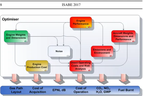
The conceptual design algorithm and computational framework proposed in this work, and described in detail below, aim to automate part of the aero engine design process. The pro-posed approach spans typical aero engine conceptual design and preliminary design, featuring a sophisticated explicit modular design, addressing major component design as well as aircraft system level performance. The modular approach utilised is illustrated in Fig. 1. Individually developed modules are integrated together in an optimiser environment; a large amount of information is available after every design iteration and can be used for many purposes such as technology impact assessment, sensitivity and parametric studies, multi-objective optimi-sation etc. This design architecture has some inherent advantages such as:
• Accelerated tool development and lower maintenance cost - Improvements in an individ-ual module are possible without modifications to the rest of the modules i.e. the whole system does not need to be recompiled every time.
• Legacy code utilisation - Existing codes can be used with minimal to no adaptation through the use of custom wrappers.
• Module plug-in/plug-out capability - Individual modules can easily be replaced by more sophisticated OEM proprietary codes.
Figure 1. Framework modular structure.
• Run-time flexibility - Modules can be switched-off during particular simulations to im-prove the speed of execution, assuming their output is not of interest to the user.
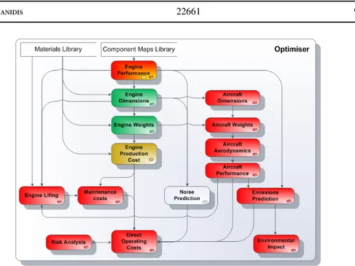
Since the main use of such a framework would be to asses new engine technologies, a dif-ferent approach - than the typical practice described earlier - needs to be adopted to simplify the conceptual design process. Therefore, the proposed algorithm first defines an engine ther-modynamic cycle from a set of performance parameters, and then performs a full gas path layout design. For every individual engine design, the aircraft is scaled (from a baseline de-sign) to satisfy the defined payload-range requirement based on the new engine dimensions, weight and performance. Some of the architectural details on which the present work has been inspired from are given in(5). The actual conceptual design algorithm as presented here is illustrated in Fig. 2, while details are given for each module in the following sections.
One of the major efforts with the presented approach has been to remove - wherever possi-ble - nested loops/iterations typically encountered in conventional conceptual design. Use of the proposed explicit algorithm minimises internal iterations, reduces system complex-ity, improves computational speed, and through a good set of constraints it will also give an optimal aero engine conceptual design that may be feasible in terms of major engine certification and customer requirements.
It must be noted that the conceptual design algorithm and computational framework pre-sented herein is not an expert system. It is in essence a design tool that requires a practitioner with experience in engine preliminary design, including a good understanding of engine per-formance and component design, as well as sufficient knowledge of the capabilities of the technologies under assessment. Results emanating from the proposed approach can have meaningful interpretations only when the underlying assumptions in the conceptual design algorithm are well understood by the practitioner.
Figure 2. Framework conceptual design algorithm.
2.5 Module description
The individual modules that constitute the integral parts of the proposed conceptual design approach are described in the following subsections.
2.5.1 Engine performance
The proposed conceptual design algorithm first starts by defining an engine thermodynamic cycle from a set of input performance parameters. During this procedure, the top of climb condition (Alt= 35000 [ft], Mcr, ISA+10 [K]) is set as the performance design point for the purpose of component map scaling and nozzle area calculations. The user may alter the engine cycle at top of climb by varying typical performance parameters such as fan pres-sure ratio, bypass ratio, overall prespres-sure ratio, IPC/HPC (Intermediate Pressure Compressor / High Pressure Compressor) work split, combustor outlet temperature, cooling mass flow ra-tios, component efficiencies, heat exchanger effectiveness etc. This operating condition has been chosen since it is typically the point where the highest component corrected flows are encountered in modern high bypass ratio turbofans, and hence it is important for component aerodynamic design.
Climb, cruise and descent ratings are then calculated as extended performance tables to be utilised in the downstream aircraft performance analysis. Important engine operating condi-tions are also simulated as steady-state off-design points, including:
• Mid-cruise (Alt= 35000 [ft], Mcr, ISA)
• Hot day end of runway take-off (Sea-level, M = 0.25, ISA +15 [K]) • ICAO emissions certification take-off 100% FN (ISA SLS)
• ICAO emissions certification approach 30% FN(ISA SLS) • ICAO emissions certification idle 7% FN(ISA SLS)
• ICAO noise certification sideline (Alt= 300 [m], M = 0.26, ISA +10 [K]) • ICAO noise certification cutback/flyover (Alt = 300 [m], M = 0.26, ISA +10 [K]) • ICAO noise certification approach (Alt= 118 [m], M = 0.222, ISA +10 [K])
The mid-cruise operating condition is important for the cycle efficiency optimisation as well as for component aerodynamic design. The hot day end of runway take-off condition is necessary for the thermo-mechanical design, particularly for cooling flow selection and max-imum cycle temperature and rotational speed setting. Finally, the ICAO points are important in order to estimate engine performance with respect to noise and emissions legislation.
For all these steady-state operating points and ratings, a practitioner needs to choose the main engine control parameter such as combustor outlet temperature or net thrust, or prac-tically measurable parameters such as low pressure shaft rotational speed, and low pressure turbine temperature. Similarly, potential secondary control parameters such as low pressure turbine capacity, nozzle areas, variable guide vane angles or intercooler effectiveness schedule for engines with variable geometry nozzles.
In principle, no iterations are performed for take-off and climb thrust requirements, or cool-ing mass flow and velocity ratio re-optimisation; this speeds up the optimisation process sub-stantially. Constraints for output parameters such as compressor delivery temperature, high pressure turbine rotor metal temperatures, or even time between overhaul (a value calculated in the lifing part of the economics module) are instead set at the end of the calculation se-quence. A multi-point design approach is utilised and the interested reader is referred to the detailed presentation given in (67). Nonetheless, individual input and output parameters may still be fixed adlib in such cases where it is expected to enhance the designers understanding, for example during a sensitivity analysis study of a new concept or technology.
Engine performance modelling is primarily based on the use of generic compressor and turbine characteristics as well as empirical correlations(78). Component characteristics are scaled based on the procedure outlined in(50) at the hot-day top of climb condition; nozzle throat areas are also determined at the same operating condition. This particular choice for the reference condition is consistent with recent modelling work presented in(1). Off-design matching is achieved using the generic matching procedure presented in(10). All thermody-namic calculations are based on the assumption of an ideal gas (i.e., variable specific heat capacity); therefore, the main thermodynamic equation used is the Gibbs equation. The HPT Thermal Barrier Coating (TBC) average external surface blade metal temperature and corre-sponding cooling flows are modelled using the simplified approach presented in(28).
2.5.2 Engine dimensions, weights and production cost
Thermodynamic data from the engine performance module are used to perform a full gas path layout design. The thermo-mechanical design is carried out at the most demanding condition i.e., hot day end of runway take-off condition, using a component by component approach. Where aerodynamic design is concerned, most components are typically designed at the top of climb condition where the highest corrected flows are encountered, but mid-cruise is also considered with maximum efficiency in mind. The full engine geometry is subsequently used to calculate the total engine weight in a similar component by component approach.
The full engine geometry is also used for calculating the engine production cost using a bottom-up approach. The engine is broken down into components, and each component is consecutively broken down into smaller parts. The cost assessment for each part is further divided into material and manufacturing cost. The final result is an assumed typical engine and parts cost to the operator, rather than the true unit cost. More details on the approach utilised for deriving the engine production cost are given in(3).
2.5.3 Aircraft dimensions, weights, aerodynamics and performance
In an iterative design process the aircraft needs to be scaled to the new engine design and predict block fuel for a given set of payload-range requirements. Climb, cruise and descent rating extended performance tables are used for this, as well as additional performance data for take-off, approach and landing, taxi and hold. The engine weight and dimensions, calculated upstream in the conceptual design sequence, are also considered.
The aircraft drag polar and weight breakdown are predicted at component level from the aircraft geometry and high lift device settings for the take-off and approach phases. Fuel burned is calculated for the entire flight mission including reserves as illustrated in Fig. 3. Cruise is performed at the optimum altitude for specific range (fixed cruise Mach number) using a step-up cruise procedure as the aircraft gets lighter. A comprehensive take-off field length calculation is performed for all engines operating and one engine inoperative conditions up to 1500 feet. The aircraft dimensions modelling is based on(21), while aircraft weight modelling followed the principles outlined in(21,66,74). The aircraft aerodynamics are modeled according to(21,9), and aircraft performance modelling is based on(21,41).
During design space exploration a rubberised∗aircraft wing model is used to capture ”snow-ball effects” with respect to maximum take-off weight variation. It offers a simplified method for aircraft scaling, that covers the major aircraft/engine conceptual design interactions i.e. first order effects. The given aircraft configuration is adapted, on a constant wing loading and aspect ratio criterion, in order to suit the new engine design (i.e. performance, weight and geometry) as well as to satisfy the defined payload-range requirements. Once the aircraft geometry has been set for the aircraft design range, a second set of fuel burned calculations is performed for the business range with the aircraft geometry fixed this time. All aircraft performance data fed to the modules downstream in the conceptual design sequence are for the business range.
As the aircraft gets lighter during the flight mission profile, less thrust is required for cruise; therefore the engine will gradually be operated at a lower combustor outlet temperature. A lighter, smaller and more efficient engine means that the aircraft will be lighter to begin with, resulting in a lower maximum take-off weight design requirement. The aircraft wing will therefore be resized to meet the new lift requirements while the tail plane is also resized to retain aircraft stability. Changing the aircraft wing and tail area essentially means that their weight will change, hence, the overall aircraft operating empty weight will change (first snowball effect). It also means that the drag polar will change (second snowball effect). The weight of other components also changes in some cases; for example the landing gear systems will be resized using the new maximum take-off weight design requirement. The fuel tank volume is recalculated for the new wing size and a check is made to confirm that the fuel tank ∗
Rubberised refers to an aircraft geometry and weight that is optimised to meet the performance specification of the integrated engine.
Figure 3. A typical flight cycle.
volume is sufficient for the given mission. The overall aircraft scaling procedure eventually results in lower cruise thrust and combustor outlet temperature requirements. In conclusion, the required cruise thrust, combustor outlet temperature and specific fuel consumption will not only vary during the cruise phase to account for the aircraft getting lighter - due to the mass of fuel consumed - but will also vary for every new individual engine design during the design space exploration.
It is therefore hard to set a fixed mid-cruise point for which consistent analysis could be performed for the entire design space - this being a typical approach used in conceptual design with fixed aircraft geometry assumption. For example, for a 12500 [km] design range mission, the cruise calculation is broken into more than 800 segments/points. The mid-cruise point could in this case be selected to be the middle point in the distance covered during cruise, but then care should be taken in analysing it’s variations (in terms of thrust, specific fuel consumption, and combustor outlet temperature requirements) as one would have to keep in mind that it’s not only affected by engine performance effects but by aircraft design as well. Also care would need to be taken during optimisation since this selection could result in numerical noise every time the middle point coincides with a step-up cruise altitude change.
To avoid potential numerical un-smoothness issues, when single point mid-cruise analysis is required, the proposed approach considers a time-averaged engine cruise operating point which is based on the scaled aircraft actual performance results.
In principle, no iterations are performed for take-off and climb thrust requirements. Con-straints for output parameters such as FAR (Federal Aviation Regulations) take-off field length, time to height etc. are only set at the end of the conceptual design calculation se-quence. This improves computational speed and allows interesting trade-off studies such as trading take-off field length for engine life, direct operating costs and/or fuel efficiency.
2.5.4 Emissions and environmental impact
Thermodynamic data from the engine performance module are used to predict the emissions levels for the ICAO LTO (Landing and Take-Off) cycle, as well as interpolated thermodynamic data from the aircraft module, for the business case mission, to predict the emissions levels for the entire flight profile.
The DpNOx/Foofigure is calculated and compared against ICAO Annex 16 Volume II leg-islative limits(19), as well as the medium and long term technology goals set by CAEP(58). There are currently no regulatory limits set for pollutants emitted above 3000 [ft] (i.e. for the climb, cruise and descent flight phases), despite the fact that potential regulation methodolo-gies for such purposes have been under discussion for a long time(54,51,59). A large number of public domain semi-empirical correlations may be used for such an assessment, each of which being suitable for a particular combustor concept such as rich-burn single-annular, rich-burn dual-annular, or lean-burn design. The approach presented in(35)is used herein primarily due its generality.
The environmental impact of a given engine/aircraft combination can be estimated by the module in terms of GWP (Global Warming Potential) using NOx, CO2 and gaseous H2O emissions estimates for the entire business case flight profile and a parametric GWP model from(71)with a selected time horizon of 100 years; this approach was chosen for its simplicity and computational speed compared to employing a sophisticated 3D climate model. GWP is an index that attempts to integrate the overall climate impacts of an emitted pollutant over a time horizon of 100 years, essentially relating the impact to that of an equivalent mass of CO2. The GWP values for gaseous H2O and NOxutilised in the environmental impact model are given in Table 1.
It should be noted that there are large uncertainties in environmental impact results pro-duced with GWP models, particularly with short-lived species such as H2O and NOx. The Intergovernmental Panel on Climate Change states(20):
To assess the possible climate impacts of short-lived species and compare those with the impacts of the long-lived greenhouse gases, a metric is needed. However, there are serious limitations to the use of global mean GWPs for this purpose. While the GWPs of the long-lived greenhouse gases do not depend on location and time of emissions, the GWPs for short-lived species will be regionally and temporally dependent.
Although, some newer GWP implementations may seem more adequate as a metric for short-lived species, no consensus has been reached yet by the scientific community on a val-idated metric for the environmental impact of aviation induced emissions(65). To that extent, Forster et al.(12) argues that it is still premature to include the effects of short-lived species in policy schemes for aviation. Details on metrics currently under evaluation are given in(26,11,13).
Table 1
Global warming potential figures for CO2, H2O(g) and NOxversus altitude (reproduced from(71)). Altitude [km] CO2GWP H2O(g) GWP NOxGWP 0 1 0.0 -7.1 1 1 0.0 -7.1 2 1 0.0 -7.1 3 1 0.0 -4.3 4 1 0.0 -1.5 5 1 0.0 6.5 6 1 0.0 14.5 7 1 0.0 37.5 8 1 0.0 60.5 9 1 0.0 64.7 10 1 0.24 68.9 11 1 0.34 57.7 12 1 0.43 46.5 13 1 0.53 25.6 14 1 0.62 4.6 15 1 0.72 0.6 2.5.5 Noise
Thermodynamic data from the engine performance module, detailed engine component geom-etry from the engine dimensions and weights module, and aircraft geomgeom-etry and flap settings during take-off and approach are used for estimating the noise produced, by all major sources, for the main ICAO noise certification points i.e sideline, flyover/cutback, and approach. The trajectory points as well as the relevant times required to reach each point, are fixed, and there-fore improvements in aircraft take-off performance are not accounted for. Heat exchanger, auxiliary nozzle effects and combustion noise for lean burning concepts are not considered, but airframe noise is accounted.
A detailed accounting of the individual methods used to consider each noise source is pre-sented in(30). A cumulative EPNL figure is calculated according to the ICAO Annex 16 certi-fication procedures and compared against the certicerti-fication limits(18). The resulting margin is fed to the optimiser and at the end of the calculation procedure the design will be judged for its feasibility.
2.5.6 Economics
The Direct Operating Costs (DOC) for the engine/aircraft combination over a given time period are calculated using a large amount of data from all upstream modules in the conceptual design sequence. Various elements are accounted for including:
• Inflation
• Fuel price volatility • Lifing considerations • Noise, CO2and NOxtaxes
The maintenance part of the DOC depends mainly on production cost and time between overhaul calculations. Time between overhaul calculations involve a high pressure turbine stress, creep and fatigue analysis using material information from a common material prop-erties library and the component geometry as designed upstream in the conceptual design sequence; cooling effectiveness, thermal barrier coating effects, and average high pressure turbine rotor inlet temperature values for take-off, cruise, climb, descent, and reverse-thrust operation are considered. Weibull distributions are utilised to account for the uncertainty of other engine components failing, including the high pressure compressor, combustor, and life-limited parts. The overall approach is described in detail in(56)and(21).
2.6 Model validation and uncertainties
In order to yield useful information from sensitivity studies as well as reasonably accurate optimisation results, when using the proposed approach, it is paramount that:
• A validation process is carried out for the engine/aircraft model
• The uncertainty levels in the methodologies used are aligned and well understood In the validation process involving the presented approach the first step is to set up the en-gine performance model. For every new technology and enen-gine configuration initial estimates of the potential performance will need to be made using expert knowledge from component specialists. As the research activities raise the TRL of each technology, so improved com-ponent efficiency estimates become available. If such a computational framework is being used in a situation where a limited amount of information is being made available such as in integrated collaborative projects or in competitor product modelling - which implies for exam-ple the use of generic component characteristics - then further model calibration is required, typically against a specification provided by an OEM.
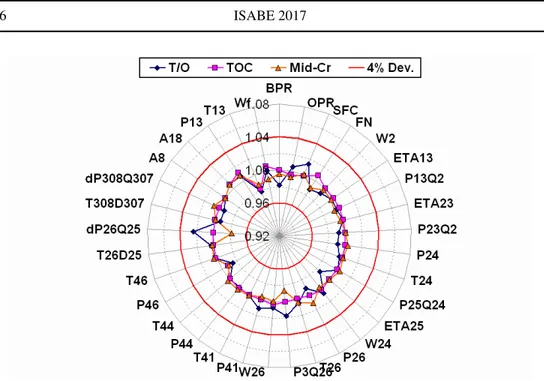
An example of the accuracy of a calibrated performance model - developed for an inter-cooled recuperated core turbofan engine for long range applications, assuming a year 2020 entry into service technology - against information provided by OEMs, is illustrated in Fig. 4. Deviations between model predictions and OEM specification are restricted for all perfor-mance parameters to roughly 2% for the three major operating points. There is little merit in attempting to achieve better model alignment using generic component characteristics. An OEM engine performance model accuracy for a pre-production engine during the concep-tual design phase may typically be no better than to within 1% SFC; at part-load the model uncertainty is expected to be significantly higher.
Where engine mechanical and aerodynamic design is concerned it is important that engine components are sized at the appropriate operating conditions. Component sizing methods need to be checked for physical behavior as the thermodynamic cycle is varied during the optimisation process. Similarly to engine performance models, there is again little merit in attempting to calibrate component weight models against an OEM specification to achieve deviations of less than 5%. Where aircraft weight and performance modelling is concerned
Figure 4. Deviations of engine performance model predictions from OEM specifications for the long range intercooled recuperated core turbofan engine.
the uncertainty levels may be roughly similar; 2% in block fuel and 5% in each aircraft weight group (wing, fuselage, landing gear etc.) pose as reasonable deviation targets.
It is important to note here that the proposed approach is primarily intended for comparing and helping to rank future technologies and design concepts. It is therefore trends that need to be captured properly (i.e., the effect on block fuel from introducing or improving a particular engine technology) rather than absolute values. Such trends can be predicted sufficiently accurately, if the engine/aircraft models have been calibrated at the above proposed accuracy levels, as long as the modelling has been performed on a formal and consistent basis. This of course implies that the systems expert carrying out the study has sufficient knowledge of the capabilities of the technologies under assessment.
Where the engine and airframe noise prediction models are concerned, calibrating noise estimates to within 1 [EPNdB] per component (or better said, per noise source) should be sufficient. With EPNL figures being very much dependent on the selected aircraft flight path, it is reasonable to expect uncertainty levels of a few [EPNdB] for the predicted noise levels for each one of the three main ICAO noise certification points; noise predictions at approach conditions will also tend to be affected by uncertainties in the engine performance predictions. Calibrating NOxprediction models to an accuracy to within about 10% is also reasonable. Actual uncertainty levels during the preliminary design of novel combustor concepts may be much higher; emission predictions at part-load will also be affected by uncertainties in the engine performance predictions. Furthermore, and as discussed earlier, no consensus has been reached yet by the scientific community on a validated metric for the environmental impact of aviation.
Where cost estimates are concerned these are highly dependent on the assumptions being made. Although the presented framework is capable of performing risk analysis to consider fuel price volatility, engine lifing etc. the framework still needs to be further developed to fully
consider robust design - rather than traditional deterministic analysis - in a computationally efficient manner.
2.7 Engine design feasibility and optimisation
In order to speed up the execution of individual engine designs, the proposed approach at-tempts to minimise internal iterations in the calculation sequence through the use of the ex-plicit algorithm described in the previous sections. Aero-engine designs however are subject to a large number of constraints and these need to be considered during conceptual design.
Constraints in the presented framework are applied through the optimiser environment pro-cedures at the end of the calculation sequence i.e. after the the economics module has been executed. During a numerical optimisation the framework will select a new set of input design parameters for every iteration and the resulting combination of aircraft and engine will be as-sessed. Using user specified objective functions the optimiser will home in on the best engine designs, determining the acceptability/feasibility of each design through the constraints set by the user. Infeasible designs will be ruled out, while non-optimum design values will result in engine designs with non-optimum values for the objective function selected. The optimiser will therefore avoid regions in the design pool that result in infeasible or non-optimum engine designs.
Design constraints set by the practitioner can include among others:
• Take-off HPC delivery temperature and other important performance parameters. • FAR take-off field length for all engines operating and balanced field length for one engine
inoperative conditions. • Time to height.
• LTO DpNOx/Foovs. ICAO certification limits and CAEP medium and long term goals. • Cumulative EPNL vs. ICAO certification limits.
• Engine time between overhaul.
For example, during a block fuel optimisation all engine aircraft combinations which do not fulfil the take-off and time to height criteria set will be discarded as infeasible. Due to the underlying physics of the presented framework, this will lead to an optimal engine and aircraft combination for the defined objective function. All large engines will produce heavier aircraft with more drag and thus higher block fuel weight. Engines which are too small will not deliver enough thrust to satisfy the take-off and time to height criteria.
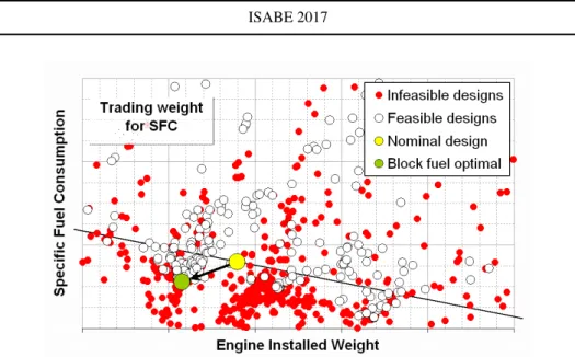
A simplified example of utilizing the presented framework for design space exploration, with active constraints, is illustrated in Fig. 5. In principle, nacelle drag should also be added as a third dimension when plotting design space exploration results that consider varying levels of specific thrust, but this has been omitted here in order to simplify the plot. The aircraft exchange rates for the baseline design were used for plotting a constant block fuel line (ignoring nacelle drag effects and nonlinearities) and this iso-line therefore defines, in a simple manner, the boundaries of trading specific fuel consumption for weight. During a block fuel optimization, the optimizer continuously evaluates different engine designs as it searches for the optimal solution. Designs that fail to meet constraints set by the practitioner are discarded and have been labeled as infeasible in the plot.
Figure 5. Visualization example of constrained design space exploration.
3.0 RESULTS AND DISCUSSION
Relevant case studies have been selected and are presented in this section in order to demon-strate the power of the proposed approach for:
• Technology assessment(31,33,34,40,35) • Design sensitivity analysis(37,57)
• Design space exploration(38,56)and optimization(67,36).
3.1 Technology assessment
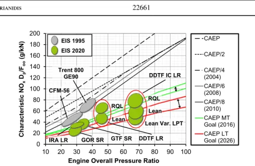
The presented approach can be used for carrying out NOx emissions assessments of future aero-engine designs incorporating modern Rich–burn Quick–quench Lean–burn (RQL) and lean-burn combustor technology. Two such assessments that focused on the prediction of NOxemissions levels for the ICAO LTO cycle of advanced novel aero-engine designs were presented in detail in(33,34). The predictions from these studies are compared through Fig. 6 against ICAO Annex 16 Volume II legislative limits(19), as well as the Medium Term (MT) and Long Term (LT) technology goals set by CAEP(58). Balloons have been used to indicate the uncertainty in the NOxpredictions. The authors have considered a ±10% overall uncertainty in the predicted NOxemissions when using the proposed correlations. In addition, a relatively small experience-based uncertainty is considered in the estimated overall pressure ratio of the various future cycles. The uncertainty is meant to cover the lower Technology Readiness Level (TRL) associated with some of the proposed future aero-engine designs. In the case of those engines already in service, namely the CFM-56, Trent 800 and GE90, the bubbles have been sized to cover the spread in the information contained in the ICAO databank for the different variants of each engine model.
The study identified that a sufficient margin against the ICAO CAEP/8 LTO cycle NOx certification limit may be achieved for all the configurations that have been assessed assum-ing technology levels consistent with a year of entry into service around 2020. Lean-burn
0 20 40 60 80 100 120 140 160 180 200 10 20 30 40 50 60 70 80 90 100 Characteristic NO x Dp /Foo (g/kN)
Engine Overall Pressure Ratio
CAEP CAEP/2 CAEP/4 (2004) CAEP/6 (2008) CAEP/8 (2010) CAEP MT Goal (2016) CAEP LT Goal (2026) Trent 800 GE90 CFM-56 DDTF IC LR DDTF LR EIS 1995 EIS 2020 GTF SR GOR SR IRA LR RQL Lean RQL Lean Lean Var. LPT
Figure 6. NOxemissions assessment for different future aero engine design concepts (DDTF LR: Direct–Drive TurboFan for Long Range applciations; DDTF IC LR: Direct-Drive TurboFan with Intercooled Core for Long Range Applications; IRA LR: Intercooled Recuperated turbofan for Long Range applications; GTF SR: Geared
TurboFan for Short Range applications; GOR SR: Geared Open Rotor for Short Range applications).
combustion technology can offer improved NOxperformance when compared to RQL tech-nology, particularly if coupled with variable geometry Low Pressure Turbine (LPT) nozzle guide vanes that can help modulate the combustor primary zone Air Fuel Ratio (AFR) at part-load conditions.
Nonetheless, it can been observed in Fig. 6 that despite the improved certification margin, absolute NOx emissions per passenger-kilometer are likely to increase at least for some of the proposed concepts. It is not fully clear which design parameters drive this increase and what their impact might be on high-altitude NOxemissions, which are currently not covered by any legislation. An earlier study presented in(8) did attempt to shed some light on this topic but had several shortcomings. The authors failed to separate the effect of specific thrust (propulsive efficiency) and OPR (thermal efficiency) on NOx emissions. A fully rigorous engine performance model was also not utilised, which meant that it was not possible to study the engine behaviour at different operating conditions i.e., sea-level versus high-altitude. These important interrelationships have been investigated and discussed in detail in(35)using the presented framework and some of these results are presented below.
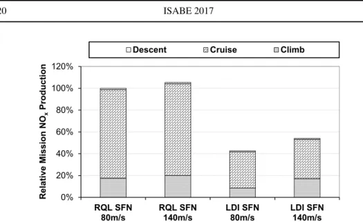
The absolute amount of NOxemitted during a typical long–haul flight decreases with de-creasing specific thrust, as illustrated in Fig. 7. This behaviour can be observed for both RQL and Lean Direct Injection (LDI) combustor technology and is attributed primarily to aircraft-level snowball effects from the resulting reduction in SFC. Cruise NOxemissions are particularly low for LDI combustors - largely independently of specific thrust level - since around this point the design tends to operate at its optimum performance.
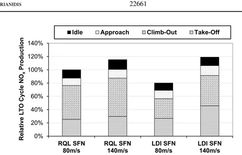
The amount of NOx emitted during a typical LTO cycle also decreases with decreasing specific thrust, as illustrated in Fig. 8. This behaviour can be observed for both RQL and LDI combustor technology and is attributed primarily to the expected reduction in EINOxat high-power. LDI combustors are particularly sensitive at high-power conditions; their performance is largely dependent on the primary zone flame temperature ratio between take-off and cruise.
0% 20% 40% 60% 80% 100% 120% RQL SFN 80m/s RQL SFN 140m/s LDI SFN 80m/s LDI SFN 140m/s Relative Mission NO x Production
Descent Cruise Climb
Figure 7. Variation in total mission NOxemissions with specific thrust and combustor technology.
This ratio tends to reduce with reducing specific thrust and therefore LDI technology is found to be particularly suitable for low specific thrust turbofan designs.
Overall, reducing specific thrust has a more pronounced (and beneficial) effect on LTO NOx, rather than mission NOx, and this holds particularly true for LDI combustors. This suggests a gap in the current certification legislation which seems to favour reduced sea-level NOxover high altitude NOx.
3.2 Sensitivity analysis
The presented approach can also be used for deriving averaged exchange rates for investigat-ing the effect of technology parameter deviations on block fuel i.e. at aircraft system level. The exchange rates presented in Fig. 9 were derived in(37)for an intercooled core geared fan turbofan engine by keeping all design parameters including thrust at their datum values and introducing single perturbations, one for each technology target parameter, at hot-day top of climb conditions. The technology target parameters studied were: component polytropic ef-ficiencies, duct, combustor and intercooler pressure losses, and High Pressure Turbine (HPT) Thermal Barrier Coating (TBC) average external surface metal temperature (by varying the HPT cooling flow).
The sensitivity parameters compiled allow for system level quantification of the importance of research on specific component technologies i.e. they can be used to assess the importance of progress in specific component technologies for this engine configuration. Inversely, they also help quantify the impact of technology shortcomings. Further details on the precise derivation of these exchange rates are provided in(37).
It can be observed that the influence of the low pressure system component technology on performance is quite marked for the geared variant of the intercooled core configuration for long range applications. This is justified considering the fact that this a fairly low spe-cific thrust design. In fact, the low pressure system component technology has the greatest influence on performance, as expected for an ultra high bypass ratio engine; significant fuel benefits are expected by improving fan and LPT efficiency. Inversely, shortcomings in
meet-0% 20% 40% 60% 80% 100% 120% 140% RQL SFN 80m/s RQL SFN 140m/s LDI SFN 80m/s LDI SFN 140m/s Relative L T O Cycle NO x Production
Idle Approach Climb-Out Take-Off
Figure 8. Variation in LTO cycle NOxemissions with specific thrust and combustor technology.
ing projected technology targets for the low pressure system will have a major impact on overall engine/aircraft performance.
With fan mass flow increasing and fan tip pressure ratio reducing, pressure losses in the bypass duct tend to have an increasingly dominant effect on transfer efficiency and, hence, on the impact of propulsive efficiency improvements on SFC. As can be observed in Fig. 9, a 1% increase in bypass duct pressure losses will reduce the projected block fuel benefits by roughly 2.2%. It should be noted here that previous work(38)has indicated that a 10 [in] increase in fan diameter and the consequent reduction in specific thrust is unlikely to give more than a 0.85% improvement in block fuel.
The efficiency of the Intermediate Pressure Compressor (IPC) has a significantly smaller influence on block fuel, compared to the High Pressure Compressor (IPC), which reflects the significantly higher pressure ratio placed on the High Pressure (HP) shaft and despite the beneficial effects on compressor work due to intercooling. Similarly, the efficiency of the HPT has a substantially lower influence on block fuel, compared to the LPT for the same reasons. The influence of jet pipe and combustor pressure losses, as well as HPT external surface blade metal temperature on block fuel is far from negligible. Failure to deliver the expected efficiency levels for the compressor components will increase combustor inlet temperatures resulting in higher NOx levels and reduced component life; combustor designs are highly sensitive to inlet conditions and it is highly likely that a significant shortcoming in compressor efficiency would result in a re-design of the combustor.
It can be observed, that intercooler pressure losses have a non-negligible effect on block fuel. Losses in the intercooler hot stream are relatively more important compared to losses in the cold stream, although it should be expected that losses in the cold stream should become increasingly important as the intercooler mass flow ratio (W132Q25) is increased. Failure to achieve the intercooler pressure loss targets set can significantly reduce the projected block fuel benefits for the intercooled core configurations.
0.0% 0.5% 1.0% 1.5% 2.0% 2.5% -1% Fan Tip Pol. Eff.
-1% IPC Pol. Eff. -1% HPC Pol. Eff. -1% HPT Pol. Eff -1% LPT Pol. Eff. -10K HPT TBC Tex +1% Bypass dP/Pin +1% Jet Pipe dP/Pin +1% Comb. dP/Pin +1% IC Core dP/Pin
+1% IC Bypass dP/Pin Block Fuel
Specific Fuel Consumption
Figure 9. Sensitivity analysis for different technology target parameters.
-4.0% -2.0% 0.0% 2.0% 4.0% 2.2 2.5 2.8 3.1 3.4 Ch an ge in B usi ne ss C ase Blo ck F uel (Co rr ec ted)
FAR Take-Off Distance (km) Fuel Optimal 3 -4.0% -2.0% 0.0% 2.0% 4.0% -10% -5% 0% 5% 10% Ch an ge in B usi ne ss C ase Blo ck F uel (Co rr ec ted)
Change in Engine Weight Fuel Optimal 3
3.3 Design optimization
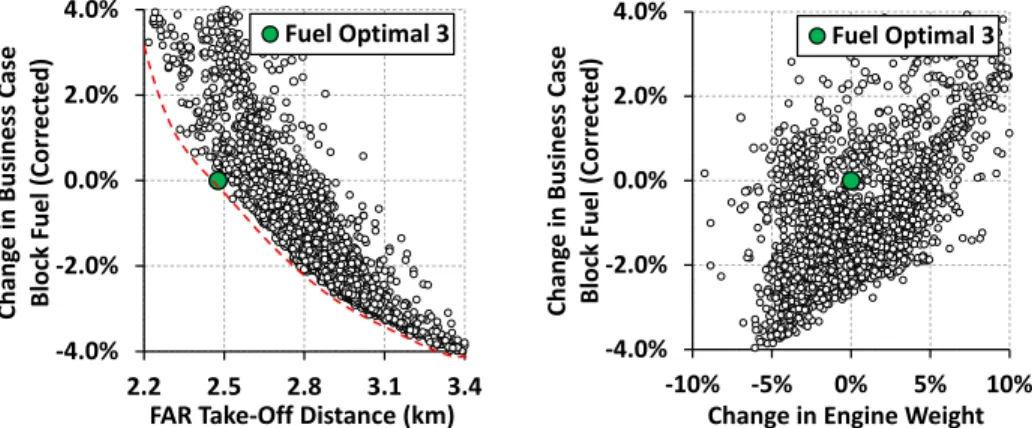
Another useful application for the proposed conceptual design algorithm and presented com-putational framework is design optimization at aircraft system level. In such studies the focus is placed on identifying the “globally” fuel optimal values of key engine design parameters while satisfying all customer requirements e.g. time to height and FAR take-off distance.
In the results presented in Fig. 10 from (36), the green circle indicates the fuel optimal design for a FAR take-off distance of 2.5km. It can be observed that customer requirements such as FAR take-off distance play a very important role in determining a fuel optimal engine design. Tougher customer requirements result in bigger and heavier engines that burn more fuel. It can also be observed that varying key engine design parameters such as specific thrust, overall pressure ratio and other has a considerable effect in terms of engine weight. Hence, it is important to consider an aircraft system level metric for fuel efficiency i.e., block fuel, rather than rely on an engine system level metric such as specific fuel consumption.
4.0 CONCLUSION
The research effort presented in this paper focused on various aspects of a multi-disciplinary aero engine conceptual design approach and computational framework for assessing the im-pact of technology advancements on future turbofan engine emissions and direct operating costs. Firstly, a brief review of some conceptual design tools was carried out and the merits and shortfalls of such tools were discussed. The development of a new conceptual design approach was presented; this work considered the following disciplines: engine performance, engine aerodynamic and mechanical design, aircraft design and aerodynamic performance, emissions prediction and environmental impact, engine and airframe noise, and production, maintenance and direct operating costs.
In relation to the proposed algorithm, the main findings presented in this work can be summarised as follows:
• From the conceptual design tools reviewed, most codes failed to consider one or more important disciplines for engine conceptual design, which can severely hinder the degree of realism during design space exploration. Unnecessary nested loops/iterations in the conceptual design algorithms were often encountered which increased system complexity and reduced computational speed, while lack of code modularity - present in some of them - affected the system’s maintainability and extendability. Furthermore, the level of fidelity used for considering each discipline may sometimes have been unnecessarily unbalanced i.e., low order codes being linked with high resolution codes upstream or downstream in the conceptual design procedure.
• To conceive and assess engines with minimum environmental impact and lowest cost of ownership in a variety of emission legislation scenarios, emissions taxation policies, fiscal and air traffic management environments, a tool following a Techno-economic, Environ-mental and Risk Assessment (TERA) - or another similar - approach is required. • The presented algorithm and computational framework can assist in the transition from
the traditional, human-based aero engine conceptual design procedure to a more auto-mated process.
• The proposed explicit conceptual design algorithm minimises internal iterations, reduces system complexity and improves computational speed; through a good set of constraints,
such an algorithm will give an optimal aero engine conceptual design that may prove feasible in terms of major engine certification and customer requirements.
• In order to yield useful information from sensitivity studies as well as reasonably accu-rate optimisation results it is paramount that a validation process is carried out for the en-gine/aircraft model. The uncertainty levels in the methodologies used need to be aligned and well understood.
The proposed explicit conceptual design algorithm reduces system complexity, improves computational speed and can make design space exploration and optimisation results easier to interpret. Through a good set of constraints, it will also give an optimal aero engine con-ceptual design that may prove feasible in terms of major engine certification and customer requirements. In relation to the specific research questions set, the benefits and power of the proposed multi-disciplinary conceptual design approach has been demonstrated through a va-riety of unique case studies. These range from technology assessment and design sensitivity analysis to design space exploration and optimization. The chosen level of detail was found appropriate for design optimization of novel engine concepts and technologies, and allowed new insights to be gained to the technology under evaluation. The overall ambition and ac-complishment of this effort has been to set the necessary base for an assessment methodology that can quantify risks and assess the impact of gas turbine design on the environment, by comparing and helping to rank future technologies and design concepts for civil aviation on a formal and consistent basis.
ACKNOWLEDGEMENTS
This study has been performed partially under the project NEWAC (European Commission Contract No. AIP5-CT-2006-030876). The authors gratefully acknowledge this funding as well as the project partners collaboration. Many thanks go to the reviewers of this work for their constructive suggestions to improve the overall quality and clarity of the article. It should be recognised that the views expressed in this article are those of the authors and not necessarily those of their respective institutions.
REFERENCES
1. Alexiou, A., Roumeliotis, I., Aretakis, N., Tsalavoutas, A., and Mathioudakis, K. Modeling Contra-Rotating Turbomachinery Components for Engine Performance Sim-ulations: The Geared Turbofan With Contra-Rotating Core Case. ASME J Gas Turb Pwr 134, 11 (November 2012). DOI: 10.1115/1.4007197.
2. Antoine, N., Kroo, I., Willcox, K., and Barter, G. A Framework for Aircraft Concep-tual Design and Environmental Performance Studies. In 10th AIAA/ISSMO Multidisci-plinary Analysis and Optimization Conference Proceedings, AIAA 2004-4314(Albany, New York, September 2004).
3. Arago, A., Bretschneider, S., and Staudacher, S. A Unit Cost Comparison Methodol-ogy for Turbofan Engines. In ASME TURBO EXPO 2007 Proceedings, GT2007-27485 (Montreal, Canada, May 2007).
4. Avell´an, R., and Gr¨onstedt, T. Preliminary Design of Subsonic Transport Aircraft and Engines. In ISABE 2007 Proceedings, ISABE-2007-1195 (Beijing, China, September 2007).
5. Bretschneider, S., Arago, O., and Staudacher, S. Architecture of a Techno-economic and Environmental Risk Assessment Tool Using a Multi-Modular Build Approach. In ISABE 2007 Proceedings, ISABE-2007-1103(Beijing, China, September 2007). 6. Canadian and US Representatives. Environmental Design Space (EDS) Progress.
pre-sented to the Seventh Meeting of CAEP, CAEP/7-IP/23, February 2007.
7. Claus, R., Evans, A., Lylte, J., and Nichols, L. Numerical Propulsion System Simula-tion. Computing Systems in Engineering (ISSN 0956-0521) 2, 4 (1991), 357–364. 8. D¨opelheuer, A., and Lecht, M. Influence of Engine Performance on Emission
Charac-teristics. In RTO AVT Symposium on ”Gas Turbine Engine Combustion, Emissions and Alternative Fuels” Proceedings, RTO-MP-14(Lisbon, Portugal, October 1998). 9. ESDU. Estimation of Airframe Drag by Summation of Components – Principles and
Examples. ESDU-97016, London, United Kingdom, September 1997.
10. Fawke, A., and Saravanamuttoo, H. Digital Computer Methods for Prediction of Gas Turbine Dynamic Response. SAE-710550, pp. 1805-1813, Society of Automotive En-gineers, February 1971.
11. Forster, P., Emmerson, K., Meinshausen, M., Raper, S., Schaeffer, M., Rogers, H., and Dessens, O. Omega Metrics - Final Report: Using Metrics to Interpret Aviation Emissions. Main Thematic Area: Climate Change, January 2009.
12. Forster, P., Shine, K., and Stuber, N. It is premature to include non-CO2 effects of aviation in emission trading schemes. Atmospheric Environment 40, 6 (February 2006), 1117–1121.
13. Fuglestvedt, J., Shine, K., Berntsen, T., Cook, J., Lee, D., Stenke, A., and Skeie, R. Transport impacts on atmosphere and climate: Metrics. Atmospheric Environment, doi:10.1016/j.atmosenv.2009.04.044 (2009).
14. Gayraud, S. Technical and Economical Assessment for Industrial Gas Turbine Selec-tion. Master’s thesis, Cranfield University, Cranfield, Bedfordshire, United Kingdom, 1996.
15. Gayraud, S. Design of a Decision Support System for Combined Cycle Schemes. MPhil thesis, Cranfield University, Cranfield, Bedfordshire, United Kingdom, 1998.
16. Gr¨onstedt, T. Development of Methods for Analysis and Optimization of Complex Jet Engine Systems. PhD thesis, Chalmers University of Technology, Gothenburg, Sweden, 2000.
17. Halliwell, I. Preliminary Engine Design - A Practical Overview. In 34th AIAA/ASME/SAE/ASEE Joint Propulsion Conference and Exhibit, AIAA 98-3891 (Cleve-land, OH, USA, July 1998).
18. ICAO. International Standards and Recommended Practices - Environmental Protection, Annex 16 to the Convention on International Civil Aviation, Volume I - Aircraft Noise. Chapter 3 and 4, Montreal, Canada, 2001.
19. ICAO. International Standards and Recommended Practices – Environmental Protec-tion, Annex 16 to the Convention on International Civil AviaProtec-tion, Volume II - Aircraft Engine Emissions. 3rd edition plus ammendments, Montreal, Canada, 2008.
20. Intergovernmental Panel on Climate Change. Climate Change 2007: The Physical Science Basis. Working Group I. IPCC Fourth Assessment Report (AR4), 2007.
21. Jenkinson, L., Simpkin, P., and Rhodes, D. Civil Jet Aircraft Design, 1st ed. Arnold, London, United Kingdom, 1999.
22. Jeschke, P., Kurzke, J., Schaber, R., and Riegler, C. Preliminary Gas Turbine Design Using the Multidisciplinary Design System MOPEDS. ASME Journal of Engineering for Gas Turbines and Power 126, 2 (April 2004), 258–264.
23. Jones, M., Bradbrook, S., and Nurney, K. A Preliminary Engine Design Process for an Affordable Capability. In RTO AVT Symposium on ”Reduction of Military Vehicle Acquisition Time and Cost through Advanced Modelling and Virtual Simulation” Pro-ceedings, RTO-MP-089-52(Paris, France, April 2002).
24. Khan, R., Barreiro, J., M.C., L., Kyprianidis, K., Ogaji, S., Pilidis, P., and Bennett, I. An Assessment of the Emissions and Global Warming Potential of Gas Turbines for LNG Applications. In ASME TURBO EXPO 2009 Proceedings, GT-2009-59184 (Orlando, FL, USA, June 2009).
25. Khan, R., Lagana, M., Ogaji, S., Pilidis, P., and Bennett, I. Risk Analysis of Gas Turbines for Natural Gas Liquefaction. In ASME TURBO EXPO 2010 Proceedings, GT-2010-23261(Glasgow, United Kingdom, June 2010).
26. Kollmuss, A., and Myers Crimmins, A. Carbon Offsetting & Air Travel Part 2: Non-CO2Emissions Calculations. SEI discussion paper, Stockholm Environment Institute, Stockholm, Sweden, June 2009.
27. Kontos, K., Janardan, B., and Gliebe, P. Improved NASA-ANOPP Noise Predic-tion Computer Code for Advanced Subsonic Propulsion Systems. NASA-CR-195480, NASA Lewis Research Center, August 1996.
28. Kurzke, J. Achieving maximum thermal efficiency with the simple gas turbine cycle. In Proceedings of 9th CEAS European Propulsion Forum: ”Virtual Engine - A Challenge for Integrated Computer Modelling”(Rome, Italy, October 2003).
29. Kurzke, J. Preliminary Design. In von Karman Institute for Fluid Dynamics Lecture Series 2002-2003, Aero Engine Design: A State of the Art(Belgium, April 2003). 30. Kyprianidis, K. Multi-disciplinary Conceptual Design of Future Jet Engine Systems.
PhD thesis, Cranfield University, Cranfield, Bedfordshire, United Kingdom, April 2010. 31. Kyprianidis, K., Au, D., Ogaji, S., and Gr¨onstedt, T. Low Pressure System Component Advancements and its Impact on Future Turbofan Engine Emissions. In ISABE 2009 Proceedings, ISABE-2009-1276(Montreal, Canada, September 2009).
32. Kyprianidis, K., Colmenares Quintero, R., Pascovici, D., Ogaji, S., Pilidis, P., and Kalfas, A. EVA - A Tool for EnVironmental Assessment of Novel Propulsion Cycles. In ASME TURBO EXPO 2008 Proceedings, GT-2008-50602 (Berlin, Germany, June 2008).
33. Kyprianidis, K., Gr¨onstedt, T., Ogaji, S., Pilidis, P., and Singh, R. Assessment of Future Aero-engine Designs with Intercooled and Intercooled Recuperated Cores. ASME Jour-nal of Engineering for Gas Turbines and Power, doi:10.1115/1.4001982 133, 1 (January 2011).
34. Kyprianidis, K. G. Future Aero Engine Designs: An Evolving Vision. In Advances in Gas Turbine Technology, E. Benini, Ed. InTech, ISBN 978–953–307–611–9, Rijeka, Croatia, November 2011, ch. 1, pp. 3–24. DOI: 10.5772/19689.