http://www.diva-portal.org
Postprint
This is the accepted version of a paper presented at 2018 International Conference on
Intelligent and Innovative Computing Applications, ICONIC 2018; Holiday Inn Mauritius
Mon Tresor Plaine Magnien; Mauritius; 6 December 2018 through 7 December 2018.
Citation for the original published paper:
Campaña, E M., Müllner, N., Mubeen, S. (2019)
Interfacing a brake-by-wire simulink model with SUMO
In: 2018 International Conference on Intelligent and Innovative Computing
Applications, ICONIC 2018, 8601239 Institute of Electrical and Electronics Engineers
Inc.
https://doi.org/10.1109/ICONIC.2018.8601239
N.B. When citing this work, cite the original published paper.
Permanent link to this version:
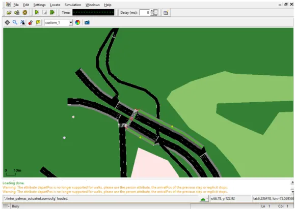
Fig. 1: The SUMO GUI showing a traffic network.
the SUMO simulation environment. The contribution in this paper is the interface/adapter connecting both, integrating the BBW as surrogate for the old braking equation, and fitting the parameters to mimic the behavior of the old system.
Fitting the parameters of the new system such that it surrogates the old braking model demonstrates the impact of this change. The adapter presented is designed to allow for Simulink models in general to be applicable as braking-system surrogates in SUMO. Utilizing the aforementioned prototype model, simulations will be run in order to check the results and adjust the adapter so that the simulation results are as close as possible to the original ones.
D. Outline
The rest of the paper is organized as follows. Section II discusses the details about how SUMO and Simulink work and how they can be employed in order to have a custom braking system simulated in SUMO. Section III discusses the design and rationale behind the adapter that allows to substitute SUMO’s braking model by a custom braking model. Section IV shows in detail how the testing of the braking system is accomplished and provides the results. Section V concludes of the paper.
II. INTERFACINGBBWANDSUMO
This section discusses the details of interfacing SUMO and Simulink and how they can be employed in order to have a custom braking system integrated in SUMO.
A. Simulation of Urban MObility (SUMO)
Generally, the traffic modeling is distinguished at four different level, which are described as follows.
1) Macroscopic level refers to the traffic flow,
2) Mesoscopic level simulations exist between microscopic and macroscopic simulations. Sets of vehicles can be modelled as queues, and vehicles are moved between the queues,
3) Microscopic level refers to the behavior of a single vehicle regarding its environment and the driver control [8], and 4) Nanoscopic level (or sub-microscopic level) addresses the (sub-)systems within a vehicle. This notation allows to address specific sub-systems on their particular level when perceived as system-of-systems model.
SUMO is a highly portable open source simulation tool, designed to be employed with large road networks. It is able to work at the microscopic level (i.e., simulating every car on the road), mesoscopic level (less detailed but faster) or macroscopic level (highly abstracted but the fastest). This paper focuses on the microscopic level.
SUMO includes a set of tools for different kinds of appli-cations, providing great flexibility. The most important one utilized here allows an online interaction with the simulation, called the Traffic Control Interface (TraCI). It allows to modify parameters of the simulation during its execution, which provides for a great amount of possibilities modifying the simulation behavior during run-time. SUMO executes in a console or with a Graphical User Interface (GUI) as shown in the example in Figure 1. The console version performs
naturally faster and is thus selected in this paper. A simulation run is specified in a configuration file before the execution. B. Simulink
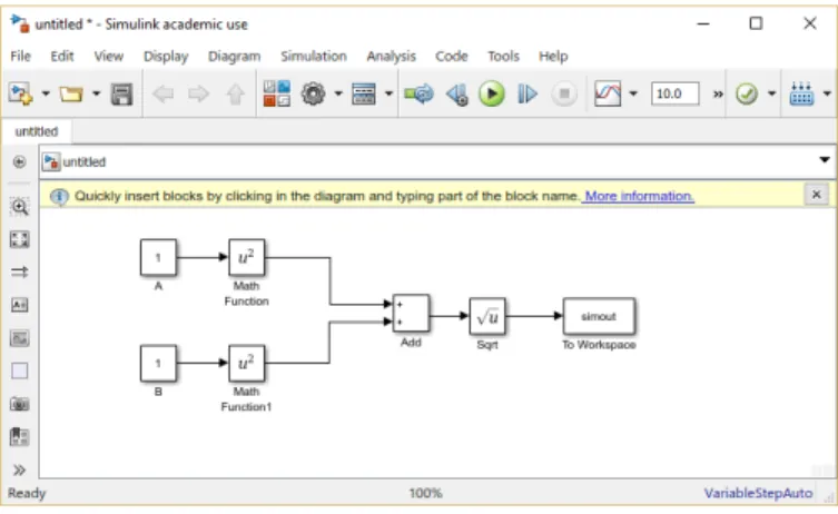
Simulink is a model-based modeling and simulation tool suite that is designed to work seamlessly together with Matlab. It is extensively adopted for modeling and simulating in var-ious fields such as signal processing, power control, robotics, just to name a few. It packs a wide amount of features such as automated code generation, simulation parallelization and custom scheduling. Figure 2 depicts the design interface of Simulink.
The BBW system developed by Volvo and introduced in the MBAT-ARTEMIS project2allows for demonstrating the
feasi-bility of the interface. To the best of the authors’ knowledge, only once has a Simulink model been interfaced in SUMO [9], [10] which did not concern a model of the braking system. One reason the BBW by Volvo qualifies as suitable candidate is that the system is available as real physical (prototypical) system, as several implementations, as (extended) UML models and as Simulink model, putting the quantitative assessment within a simulation environment like SUMO en par with discrete techniques from software testing (as discussed in the outlook in Section V).
Fig. 2: View of Simulink’s workspace.
C. TraCI4Matlab
The selected tool for connecting Simulink and SUMO via TraCI is TraCI4Matlab [11]. It is an Application Program-ming Interface (API) that allows Matlab to communicate with SUMO’s TraCI to interact directly with the executed simu-lation. Since TraCI works by creating a server where SUMO runs, TraCI4Matlab employs the TCP/IP layer to communicate MATLAB’s program that behaves as a client to it.
III. ANADAPTERLINKING THEBBWVIATRACITO
SUMO
The basic structure of the system is shown in Figure 3. The simulation in SUMO and the Simulink model that represents
2Combined Model-based Analysis and Testing of Embedded Systems http: //www.mbat-artemis.eu/
the braking system are connected via the adapter. The three components are explained below.
SUMO simulationoo // Adapteroo // Simulink model
Fig. 3: An adapter connecting SUMO to the Simulink model.
A. Simulation Environment
Figure 4 shows the selected simulation scenario, consisting of a 500 meters long road with a stop (i.e., initiating braking) at the 450 meters mark. The maximum permitted velocity is 70 m/s and the maximum velocity of the car is 100 m/s. These are arbitrary values selected so that the velocity is not a limiting factor for testing the brakes. Regarding SUMO’s behavior when approaching a stop mark, it attempts to commence braking as close to the stop mark as possible before stopping completely. This means, that the car will press and release the brake several times before it stops. After stopping, the car will stay in that position for a set amount of time before starting to move again. In this case, the time that the car is stopped is set to 20 seconds.
500m
ST
OP
Fig. 4: Test test scenario, driving from left to right.
SUMO has a default seed for random number generation set to 23423. This causes runs to have the same results if other parameters are kept the same. Whenever a variety of scenarios is desired, the simulation is initialized with a different random seed for random number generation every time (e.g., based on the system time-stamp). The command launching the simulation is as follows.
sumo -c scenarioPath --remote-port PORT --random --step-length STEPLENGTH --start The arguments’ function is:
a) -c scenarioPath: It loads the configuration file with the extension .sumocfg. This scenario file includes all the information for the simulation like the route file, the networks file or the configuration file.
b) –remote-port PORT: It selects which port is chosen to connect to TraCI. It is only needed when running several instances of SUMO with different simulations at the same time. If it is used, when initializing TraCI in MATLAB, the same port should also be specified.
c) –random: As said before, SUMO’s seed for the ran-dom number generator is always 23423. If different scenarios are needed, this option should be enabled. It will initialize the random number generator with the system time at that moment.
d) –step-length STEPLENGTH: It sets the length of a SUMO step in seconds. The step length set in all the simulations of this paper is 0.1 seconds. The default step length of 1 second does not offer enough resolution when observing the behavior of the braking system.
e) –start: This argument tells SUMO to initiate the simulation after loading the scenario.
B. Braking Model
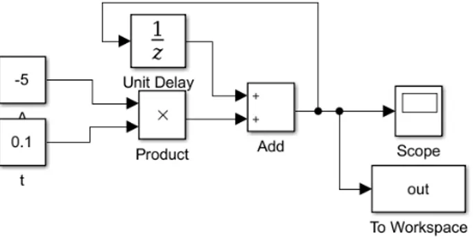
This prototype consists of a simple close loop system where for each time step in the Simulink simulation, the step size set in SUMO (0.1 seconds) is multiplied by the same acceleration that was employed in the vehicle description in SUMO (5 m/s2). This exact prototype model can be seen in Figure 5. The aim of this model is to build the adapter that makes the interaction between SUMO and the braking model possible. It is done this way because this model being very simple and equivalent to the system implemented by SUMO for the braking calculations3, any difference or problem can be easily tracked. It will also be exploited later to test the impact of the adapter in the simulation.
Fig. 5: Simulink version of old system: (V = v0+ at).
C. Design and Implementation of the Adapter
The idea behind this adapter is to substitute SUMO’s braking simulation with any braking model that is capable of outputting the speed to MATLAB.
1) Basic operation and implementation: The adapter is the component that intercepts the braking process in SUMO and substitutes it by the one in the model. For that, it follows the following process:
a) Load the SUMO simulation and the braking model in Simulink,
b) Run the simulation in SUMO step by step,
c) When the brake pedal starts being pressed, the Simulink simulation is initialized with the necessary values and run. The results from each step of the simulation are buffered in MATLAB.
d) For each step of the simulation when the brake pedal is pressed, the speed will be set according to the buffered values.
3http://sumo.dlr.de/wiki/Specification#Driving
e) If the brake is released, the control is returned to SUMO until the brake pedal is pressed again, in which case it repeats from step c).
All this process is done in MATLAB, which is able to natively communicate with Simulink and via TraCI4Matlab with SUMO.
It is important that the simulation is executed sufficiently long, such that SUMO will not request more values than there are stored in the buffer. This is accomplished by setting the simulation time to a fixed safe value, but might be set dynamically in relation to the buffer size in the future.
The braking control system is a bang-bang controller [12] (the brakes are either completely pressed or completely re-leased). Although it is possible to apply different braking forces depending on the position of the braking pedal, a function to determine such position is unavailable in the current TraCI4Matlab documentation. It would also increase the execution time substantially since the Simulink simulation would have to be reinitialized every time the position of the brake pedal changes. On the other hand, SUMO is able to manage this system with good results so this compromise between difficulty, performance and functionality seems like a good trade-off. Alternatively, the simulation of progressively pressing and releasing the brake pedal could be implemented as a part of the braking model if that was desired. In order to detect when the brakes are applied, the brake light signal is employed as the trigger, since it will be activated whenever the brake pedal is pressed.
It is important to note that if the velocity in a vehicle in SUMO is set to 0, SUMO will trigger the emergency brake. In order to avoid this situation, the adapter returns the control to SUMO if the speed is set to a value lower than 0.1mm/s. This threshold can be changed if desired. After returning the control to SUMO, it stops the car using its original braking system.
2) Settings: In order to run a custom simulation with the adapter, several steps are needed. First of all the SUMO configuration file and the Simulink model should be changed to fit the desired files. Then, if SUMO must be called with some special parameters or using the SUMO GUI, this should be changed in the line that runs SUMO. After that the only other necessary change is adding the necessary initialization values for the Simulink simulation in the designated section.
3) Engineering Decisions: The approach selected in this paper is different to the one shown in [9]. In this imple-mentation, TraCI4Matlab was chosen since it is simpler and more direct than the approach shown in said paper, as seen in Figure 6.
The downside of this approach is that according to [11] the development process of this API is based on reverse engineering of the TraCI for the Python API and it was done quickly and without performance in mind so that might lead to some features not working or underperforming. That said, its application has proven to be easy and adequate for this task.
SUMO TraCI Simulink MATLAB Matlabcontrol TraSMAPI SUMO TraCI Simulink MATLAB TraCI4Matlab
Fig. 6: Comparison of architectures in [9] (left) and this paper (right).
IV. EVALUATION
The testing and evaluation has focused on the part that could have made the greatest difference. Since slamming the brakes would result in equivalent deceleration, the test scenario is designed to require a more precise management of the brakes. This scenario, as explained in Section III-A, tries to stop the car at 450 meters from the origin. Some base results from a completely default SUMO simulation (without using an external braking model or the adapter) are presented and compared with the obtained results.
When setting up a vehicle in SUMO there is a parameter called "sigma" which determines how good the driver is. It can be set with any number from 0 to 1, being 0 a perfect driver and 1 a terrible one. Since the simulations with a sigma value of 0 resulted always in the same result, the decision was made to set sigma values of 0.5 and 1 in the simulations.
The results of the original braking system by SUMO are taken as a reference to compare the results of the custom simulations. On the other hand, the results of the simulations with the prototype braking model should show the impact of the adapter in the simulation since, as said in Section III-B, this model simulates the exact mathematical model employed by SUMO to calculate the braking.
A. Histograms of the stop position
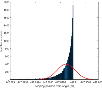
All the histograms show the distribution of the braking position of the vehicle in 20000 simulations.
Notably, in Figure 7b, there are 10 points between 428.8202 and 447.4959 meters not shown to increase readability. Both Figures 7a and 7b present sufficiently similar results. As it can be seen, most of the results are registered at the 447.9 meters mark. SUMO will never go over that threshold. This feature was discovered during the earliest tests that were made; when the sigma value of 0 was also tested and all the results returned that exact value. Being this graph representative of an average driver, all the vehicles where able to stop near the said limit. All the other results are tightly grouped around this point (without going over it).
447.8994 447.8995 447.8996 447.8997 447.8998 447.8999 447.9 447.9001 447.9002
Stopping position from origin (m)
0 500 1000 1500 2000 2500 3000 3500 Number of cases (a) Original (b) Prototype model
Fig. 7: Comparison of histograms with different braking systems, Σ = 0.5.
447.899 447.8992 447.8994 447.8996 447.8998 447.9 447.9002 447.9004
Stopping position from origin (m)
0 200 400 600 800 1000 1200 1400 1600 1800 2000 Number of cases (a) Original (b) Prototype
Fig. 8: Comparison of histograms with different braking systems and Σ = 1.
In Figure 8b there are 14 points between 447.4244 and 447.4945 meters not shown to increase readability. The results are similar to the ones in Figure 7. As expected, the results are less tightly grouped due to the sigma value of 1, simulating a very bad driver. Again, there is not one single case where the vehicle stops after the 447.9 meters limit that is set by SUMO. This shows how SUMO is able to manage the use of this braking system without loosing control of the vehicle. The dispersion pattern in both Figures 8a and 8b is seemingly similar (considering the random nature of the experiment) and shows how the behaviour of the simulation with the adapter closely resembles a simulation without it.
V. CONCLUSION
This paper showed how replacing SUMO’s mathematical model for braking by a custom one can be achieved and
explains how the adapter is designed. The paper also revealed how the adapter behaves in a different way and the impact that it causes in the simulation. This work provided both a method to employ custom braking models in SUMO as well as overview of its performance. Future work will focus on i) further test scenarios to demonstrate that similarity between old and new brakes are independent of the scenario, ii) applying different parameters in the Simulink model for assessing their individual impact, and iii) an analysis alongside the software and hardware derivatives of the BBW system to determine, if flaws (be they functional or performance related) found in one implementation can be observed in the other.
ACKNOWLEDGMENTS
The work in this paper was partly supported by the Knowledge Foundation (KKS) through the project 20130085 (TOCSYC), and by the European Union and VINNOVA under grant 692529-2 (SafeCOP).
REFERENCES
[1] M. B. Daniel Krajzewicz, Jakob Erdmann and L. Bieker, “Recent development and applications of sumo simulation of urban mobility,” in International Journal On Advances in Systems and Measurements, vol. 5, no. 3,4, 2012, pp. 128–138.
[2] C. Rhodes and S. Djahel, “Trader:traffic light phases aware driving for reduced traffic congestion in smart cities,” in 2017 International Smart Cities Conference (ISC2), Wuxi, China, Sept 2017, pp. 1–8.
[3] S. Bhargava, K. Prakasha, and I. Sinha, “Predicting traffic density and increasing fuel efficiency in vehicles using secure vehicular networks,” in 2017 International Conference on Computer Communication and Informatics (ICCCI), Coimbatore, India, Jan 2017, pp. 1–3.
[4] N. Müllner, S. Khan, M. H. Rahman, W. Afzal, and M. Saadatmand, “Simulation-based safety testing brake-by-wire,” in 2017 IEEE Inter-national Conference on Software Testing, Verification and Validation Workshops (ICSTW), Tokyo, Japan, March 2017, pp. 61–64.
[5] Y. Mingfei, “Brake-by-wire system design and simulation,” in 2012 International Conference on Computer Science and Electronics Engi-neering, vol. 3, Hangzhou, China, March 2012, pp. 248–251. [6] W. M. Griggs and R. N. Shorten, “Embedding real vehicles in sumo for
large-scale its scenario emulation,” in 2013 International Conference on Connected Vehicles and Expo (ICCVE), Dec 2013, pp. 962–963. [7] E. Martín Campaña, Brake-by-wire in SUMO: A Custom Solution for
Braking Simulation, Master of Science Thesis, School of Innovation, Design and Engineering, Mälardalen University, 2018.
[8] D. Chowdhury, L. Santen, and A. Schadschneider, “Statistical physics of vehicular traffic and some related systems,” Physics Reports, vol. 329, no. 4, pp. 199 – 329, 2000.
[9] J. Macedo, G. Soares, Z. Kokkinogenis, D. Perrotta, and Rosaldo J F Rossett, “A Framework for Electric Bus Powertrain Simulation in Urban Mobility Settings: coupling SUMO with a Matlab/Simulink nanoscopic model,” in 1st SUMO User Conference, BerlinAdlershof, Germany, 2013, pp. 95–102.
[10] J. Macedo, Z. Kokkinogenis, G. Soares, D. Perrotta, and R. J. F. Rossetti, “A hla-based multi-resolution approach to simulating electric vehicles in simulink and sumo,” in 16th International IEEE Conference on In-telligent Transportation Systems (ITSC 2013), The Hague, Netherlands, Oct 2013, pp. 2367–2372.
[11] A. F. Acosta, J. E. Espinosa, and J. Espinosa, “Traci4matlab: Enabling the integration of the sumo road traffic simulator and matlab½o through a software re-engineering process,” in Modeling Mobility with Open Data, M. Behrisch and M. Weber, Eds. Springer International Publishing, 2015, pp. 155–170.
[12] S. Chen, J. Zhao, and J. Qian, “A design method of bang-bang and pid integrated controller based on rough set,” in Fourth International Conference on Fuzzy Systems and Knowledge Discovery (FSKD 2007), vol. 2, Haikou, China, Aug 2007, pp. 529–533.
![Fig. 6: Comparison of architectures in [9] (left) and this paper (right).](https://thumb-eu.123doks.com/thumbv2/5dokorg/4682319.122583/5.918.181.738.74.332/fig-comparison-architectures-left-paper-right.webp)