A power efficient active RFID
communication Protocol
Francisco Javier Dávila García
Master Thesis 2007
A power efficient active RFID
communication Protocol
RFID Protocol
Francisco Javier Dávila García
Detta examensarbete är utfört vid Ingenjörshögskolan i Jönköping inom ämnesområdet elektroteknik. Arbetet är ett led i teknologie
magisterutbildningen med inriktning inbyggda elektronik- och datorsystem. Författarna svarar själva för framförda åsikter,
slutsatser och resultat. Handledare: Alf Johansson
Examinator: Youzhi Xu
Omfattning: 20 poäng (D-nivå) Datum: 2007-06-15
Abstract
Active Radio Frequency Identification (Active RFID) is a wireless automated technology used to identify, track, process and share information about an object or from the environment. As microcontrollers and radio frequency transponders are smaller in size, more power efficient, and less expensive, this technology is growing and starting to expand significantly through all the industries.
This thesis is the continuation to the master project done by Joakim Gustafsson who developed a fully functional active RFID system based on an already designed hardware. The main purpose of continuing with this project was to reduce the power consumption of the active tags for them to last at least one and a half years. In this master project there were no restrictions of changing the hardware, therefore the main protocol tasks were discussed and designed before the hardware, in that way the hardware was optimum for the protocol.
This master thesis required a deep and extensive analysis of the old protocol. There was a need of go deep through the software and hardware in order to come with a better energy efficient solution, and still have the same functionality. This master thesis presents a functional TDMA based protocol which was designed and developed for a specific tracking system application.
Sammanfattning
Aktiv “Radio Frequency Identification” (Active RFID) är en trådlös kommunikationsteknologi som används för att identifiera, spåra, processa och dela information om ett object eller från omgivningen. Eftersom mikrokontrollkretsar och radiofrekevens-transpondrar blir fysiskt mindre och därmed mindre energikrävande och billigare att tilllverka växer RFID-teknologin och tydlig expansion syns inom de flesta industrisegment.
Detta examensarbte är fortsättningen på ett magisterexamensarbete som gjordes av Joakim Gustafsson som utvecklade ett fullt fungerande RFID-system baserat på tillgänglig hårdvara. Huvudsyftet med att fortsätta projektet var att minska effektförbrukningen hos aktiva transpondrar (tags) så att batterilivslängden kunde bli ett och ett halvt år. I detta fortsatta magisterprojekt fanns inga restriktioner mot att förändra hårdvaran därför diskuterades kommunikationsprotokollet innan hårdvaran. Hårdvaran blev på detta sätt mer optimal för applikationen.
En ingående analys av “det gamla” protokollet krävdes. Noggrann analys av befintlig programvara och hårdvara krävdes också för att komma fram till en mer energieffektiv lösning med bibehållen funktionalitet. Detta examensarbete presenterar ett TDMA-baserat protokoll som utvecklats för en speciell spårningsapplikation.
Acknowledgments
I want to thank Alf Johansson, my supervisor and program manager, for putting me in contact with the company Combiport AB, and therefore giving me the opportunity to participate in an exciting project and to be able to work and participate in a Swedish Company.
I want to thank Werner Hilligies, my supervisor at Combiport AB, for trusting me, for being very friendly and making me feel home since the first day I came to the company. I want to thank him also for the support I received during all my thesis work, and for being positive and enthusiastic about my ideas, and work.
I want to thank Per – Erik Kristensson because he helped me enormously to develop my programming skills. I thank him for all the advices and tricks that he taught me, and for always trying to help me.
I want to thank Johan Kvist for being so friendly with me for making me feel very welcome, and giving me advices about how things work around in Sweden.
I want to thank Björn Hilligies for helping me with the hardware, and for all the discussions and new ideas that he contributed in this project.
I finally want to thank all the SafeTool AB people, Kenneth Johansson, Claes Rydin and Dan Malmqvist.
Key Words
• Radio Frequency Identification (RFID) • Wake on Radio (WOR)
• Sensor Networks • Sensor Node • Power Reduction • Active RFID
• Automatic Identification and Data Capture (AIDC) • Wireless
• Contact less • CC2500 • Radio Chip
• Time Domain Multiple Access (TDMA) • Lithium Battery
Dedication
I dedicate this thesis to three people who have been a continuous inspiration during all my education. For my mother, Maria del Carmen García Ortiz, who showed me the way to dream and opened my mind to new ways of thinking. For my father, Francisco Javier Dávila Aranda, who helped me to put my feet back to ground and taught me the importance of education. For my brother, José Roberto Dávila García, who has been my friend and support all my life.
Dedicatoria
Dedico esta tesis a tres personas que han estado presentes durante todo mi proceso educativo. A mi madre, Ma. del Carmen García Ortiz, por enseñarme a soñar y por abrirme las puertas a una nueva forma de pensar. A mi padre Francisco Javier Dávila Aranda, porque me enseño a poner los pies en la tierra y por enseñarme la importancia de la educación. A mi hermano, José Roberto Dávila García por ser mi amigo y mi apoyo durante toda mi vida.
Contents
1 Introduction ... 1 1.1 PROLOGUE...1 1.2 BACKGROUND...2 1.3 PROBLEM DESCRIPTION...3 1.4 GOAL...5 1.5 LIMITATIONS...61.6 STATE OF THE ART IN AUTOMATIC IDENTIFICATION SYSTEMS...7
1.7 DISPOSITION...8
2 Wireless Technology ... 9
2.1 RADIO COMMUNICATION BASICS...9
2.1.1 Definitions...9
2.2 WIRELESS SENSOR NETWORKS...10
2.2.1 Communication Networks ...10
2.2.2 Network Characteristics...11
2.2.3 Power Management ...12
2.2.4 Applications ...13
2.3 RFIDSYSTEMS...13
2.3.1 Passive RFID tags ...13
2.3.2 Active RFID tags ...14
2.3.3 Semi Active RFID tags ...14
3 Battery Investigation ... 15
3.1 LITHIUM BATTERIES...15
3.2 ALKALINE BATTERIES...15
3.3 RESUME...15
4 Design options and decisions... 17
4.1 APPROACH...17
4.2 OLD SYSTEM...17
4.2.1 Old Protocol Description ...17
4.2.2 Old System Hardware ...18
4.2.3 Old System Software ...19
4.2.4 Old Protocols results ...20
4.2.5 Old Protocol Analysis ...20
4.3 FIRST PROTOCOL SOLUTION...26
4.3.1 Protocol Description ...26
4.3.2 Multi-medium access control (MAC)...29
4.3.3 New System Hardware ...30
4.3.4 Protocol Timing Requirements ...30
4.3.5 Output power algorithm...31
4.3.6 Protocol Problems...32
5 Implementation... 33
5.1 FIRST STEPS...33
5.2 PROTOCOL...33
Contents
5.2.2 Wake on Radio...34
5.2.3 Synchronization mode ...35
5.2.4 Registration ...37
5.2.5 Reporting...39
5.2.6 Changing the Reporting Period...40
5.2.7 Sensing variables ...40
5.2.8 Sending data to the PC...41
5.3 PROTOCOL DETAILS...42 5.3.1 TDMA round ...42 5.3.2 Beacon Signal ...42 5.3.3 Frame Structure...44 5.4 HARDWARE...48 5.4.1 System...48 5.4.2 ATmega1281 µC...49 5.4.3 ATtiny84 µC ...50
5.4.4 Radio frequency chip: CC2500...50
5.4.5 Real Time Clock: DS1302 ...51
5.4.6 UART interface: MAX3232 ...52
5.4.7 Master-Slave Communication ...52
5.5 SOFTWARE...53
5.5.1 Partitioning...53
5.5.2 Slave Microcontroller behavior ...53
5.5.3 Master MCU behavior ...54
5.5.4 Sensor node MCU behavior...56
5.6 TESTING PROGRAMS...57
5.6.1 Development ...57
5.6.2 Inspector Software ...57
5.6.3 Battery Lifetime Calculator ...59
6 Results... 62 6.1 SUMMARY...62 6.2 EMPIRICAL RESULTS...62 6.2.1 Output Power ...62 6.2.2 Reading Distance ...63 6.2.3 Power Consumption...63 6.3 CALCULATED RESULTS...65
6.3.1 Procedure to calculate the Battery Life Expectancy ...65
6.3.2 Battery Life Expectancy Calculated Results...73
7 Conclusions ... 77
7.1 SUMMARY...77
7.2 FURTHER DEVELOPMENT...77
8 References... 79
9 Appendix ... 80
9.1 APPENDIX A:MASTER µCFLOWCHART...80
9.2 APPENDIX B:SLAVE µCFLOWCHART...83
9.3 APPENDIX C:SENSOR NODES µCFLOWCHART...85
9.4 APPENDIX D:FRAME FORMAT...88
List of Figures
Figure 1: SafeTool’s System [2] ...2
Figure 2: Tool Container...3
Figure 3: System Overview ...5
Figure 4: Protocol's battery life expectancy...6
Figure 5: Network Topologies [11] ...10
Figure 6: Self Healing Ring topology [11] ...11
Figure 7: Old System Hardware. ...19
Figure 8: Beacon search time...26
Figure 9: RC oscillator frequency...28
Figure 10: Output Power Graph...31
Figure 11: SN flow chart...34
Figure 12: Wake on Radio ...35
Figure 13: SN Synchronization Mode ...36
Figure 14: Registration Mode 1 ...37
Figure 15: Registration type 2 night option. ...38
Figure 16: Synchronization in Reporting Mode ...39
Figure 17: Changing report period...40
Figure 18: TDMA frame...42
Figure 19: Beacon Signal...43
Figure 20: Current TS and TS Description byte ...43
Figure 21: Frame Structure ...44
Figure 22: Base Station Hardware ...48
Figure 23: Sensor Node Hardware...49
Figure 24: Inspector Software...58
Figure 25: Battery Calculator Software ...60
Figure 26: Power Measurement ...64
Figure 27: New Protocol current graph (RF chip outside) ...65
Figure 28: New Protocol current graph (MCU outside) ...66
Figure 29: Old Protocol current graph (outside)...67
Figure 30: New Protocol current graph (RF chip & calibration outside) ...68
Figure 31: Old Protocol current graph (calibration outside)...69
Figure 32: New Protocol current graph (no calibration inside) ...70
Figure 33: Old Protocol current graph (no calibration inside)...71
Figure 34: New Protocol current graph (calibration inside) ...72
Figure 35: Old Protocol current graph (calibration inside)...73
Figure 36: Battery Life Expectancy (Protocol Comparison Outside)...74
Figure 37: Battery Life Expectancy (Protocol Comparison Inside) ...74
Figure 38: Battery Life Expectancy (Different power outputs)...75
List of Abbreviations
List of Tables
Table 1: Lithium and Alkaline batteries comparison [10] ...16
Table 2: Old Protocol outside Network energy analysis ...22
Table 3: Old Protocol inside Network energy analysis ...24
Table 4: Old Protocol energy analysis resume ...25
Table 5: First Proposal inside network energy analysis...27
Table 6: Comparison between the two protocols outside the network ...27
Table 7: First Proposal outside network energy analysis...27
Table 8: Comparison between the two protocols outside the network ...27
Table 9: Maximum Number of SNs...33
Table 10: Database Control Frame ...41
Table 11: Frame Control types ...46
Table 12: SN Output Power test ...62
List of Abbreviations
ADC Analogue to Digital Converter
AIDC Automatic Identification and Data Capture
AM Amplitude Modulation
ASK Amplitude Shift Keying
BS Base Station
CCA Clear Channel Assessment
CDMA Code Domain Multiple Access
CPU Central Processing Unit
CRC Cyclic Redundancy Check
CS Carrier Sense or Chip Select
CSMA Carrier Sense Multiple Access
EEPROM Electronically Erasable Programmable Read Only Memory
EMC Electromagnetic Compatibility
EPC Electronic Product Code
ESD Electrostatic Discharge
FEC Forward Error Correction
FIFO First in First Out
FM Frequency Modulation
FSK Frequency Shift Keying
GFSK Gaussian Frequency Shift Keying
GPRS General Packet Radio Services
GSM Global System for Mobile Communications
GUI Graphical User Interface
IF Intermediate Frequency
ISM Industrial, Scientific and Medical
ISO International Standards Organization
ISR Interrupt Service Routine
MAC Medium Access Control
MCU Microcontroller unit
NA Not Applicable
PCB Printed Circuit Board
PCB Personal Computer
PER Packet Error Rate
PM Phase Modulation
PSK Phase Shift Keying
QAM Quadrature Amplitude Modulation
RAM Random Access Memory
RCOSC RC Oscillator
RF Radio Frequency
RFID Radio Frequency Identification
RISC Reduced Instruction Set Computer
RSSI Received Signal Strength Indicator
List of Abbreviations
SN Sensor Node
SPI Serial Peripheral Interface
SRAM Static Random Access Memory
TDMA Time Domain Multiple Access
TX Transmission
VCO Voltage Control Oscillator
WDT Watchdog Timer
WLAN Wireless Local Area Network
WOR Wake on Radio
WSN Wireless Sensor Networks
1 Introduction
1.1 Prologue
Human perception is the ability to sense, understand, and feel the surroundings in where the individual is involved. Thinking about machines to perceive could only be common in futurist movies where robots act as human beings, talking, feeling, and comprehending thanks to the ability of sensing or perceiving the environment. Machine perception is the next step for modern technology and will be achieved with the help of RFID, bringing science fiction to life.
Radio Frequency Identification (RFID) is a technology used to identify an object, with a RFID tag, contact less and without line of sight. The id of the object, which is a serial number in form of radio waves, is sent wireless to a reader which is up to some meters apart from the object. RFID can be used as an Automatic Identification and Data Capture (AIDC) System. These AIDC systems are used to track and monitor physical objects wirelessly, without human interaction the system perceives, thinks and does everything by itself.
In the twenty century machines were designed to think, the user had to input some data, and the machine would process the data and give a result. In the twenty first century, with the help of RFID the machines will input their own data, doing the whole process totally automatic, and without human interaction. The Sensor Age has arrived, machines will sense, transmit, process, and give a result, machines will know if a stock is low, if someone is inside a building, you will know the exact time when your daughter left the school bus, the machines will know the temperature, humidity and wind conditions to decide if the a house window should be open or closed. With the help of RFID people will be able to know the best way to drive home, because it will detect traffic jams, in real time. These are just some of the possibilities that this technology will offer in the close future [4].
This wireless Automatic Identification technology will bring positive benefits to our lives. It will improve the health care by having a better distribution system, it will make business more efficient specially the manufacturing and retail supply chain, it could also help the environment by having automatic sorting of garbage, it will improve education by detecting if a student is really attending to class, it will improve library service, and much more. These are some of the thousands of benefits that RFID will bring to people, as you can see this technology will reshape the society in a point that will be impossible to live without it.
When talking of such an impact technology is also important to know how it is behaving in the market. RFID is one of the major growth industries in the world. This year the global sales will be around 3 billions $US and will be 8 times more by the year 2015 [3].
Introduction
1.2 Background
CombiPort AB is a high tech company working with RFID development and applications. The company currently is developing a new generation RFID reader for UHF generation 2 passive tags and also for active tags. The company is also developing active tags for different applications; one of the most important applications will be used by the company SafeTool AB as an inventory and control system for tools in a construction site.
Every year, expensive tools are stolen in construction sites in Sweden; there are around 6000 incidents every year and this represents around 1.5 billion SEK [2]. Due to this big problem SafeTool AB was born and came with a solution. The company develops and delivers solutions which raise the standard for security in the building industry. Through combining innovative technology with information systems, SafeTool produces products and services which increase safety and security at construction sites. SafeTool’s solutions promote efficient use and secure storage of tools and machines.
In Figure 1, the main SafeTool’s System is shown. The construction workers have an individual RFID which they use to enter to the containers. The containers send the information via GPRS so managers can access the information from any computer connected to the internet.
Figure 1: SafeTool’s System [2]
These solutions are based on active and passive RFID. Passive RFID is used to identify people; giving access to certain parts of the construction site depending in the permissions that person has in the database. The use of passive RFID in the workers id controls the access to container where the tools are stored. Active RFID is used in the expensive tools, like drills or chain saws. The tools had to periodically report to a base station telling it that they are present inside the container, in that way the system will know when a tool is inside or outside the container, and at what
time the tool was taken out and in again. A whole active RFID system was developed by CombiPort AB to attend SafeTool’s necessity; the problem was that the system didn’t fulfill the active tags power expectancies. The life expectancy of the system needed to be at least 1.5 years but the active tags could only manage 11 months of life.
Here is where this thesis gets involved; the main task is to change the communication protocol in order to increase the life expectancy of the active tags.
1.3 Problem Description
The main problem is to design an active RFID system which is capable of handling up a couple of hundreds of active tags. The active tags or sensor nodes (SN) will have different behaviors depending if they are inside the reader or base station (BS) range. The BS has to be inside a special container where all the tools of the construction site are placed. Only people with special permission and properly identified can go inside the container an take any tool they need. This is why the Suns need to have different behaviors, one behavior when the tool is inside the container and a different behavior when it is outside the container.
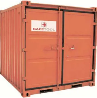
Figure 2 choose a typical tool container used in a construction site, the active RFID reader developed in this thesis will be installed in this type of containers, and the active tags will be installed inside the tools.
Figure 2: Tool Container
1. When the sensor nodes are outside the range of the BS, they should search for the BS, and when they know they are inside the BS they should transmit their id and report periodically. This period can be from 1 second to 60 seconds and the BS should decide which is the reporting period depending
Introduction
on the time of the day. The SNs have a limited power supply; they have only 220 mAH of power, this is the reason why the protocol has to consider power saving as much as possible. Once the SNs report periodically the BS has to decide if a SN is inside or outside the container. It also has to register, in the BS's database, the last report of each SN, in that way the BS knows the time when the SN left the BS.
2. The SNs should sense in the tools how much time is the tool on; this information is transferred to the BS every time the BS makes a request. The SNs can also activate or deactivate a tool if the tool has been out of the BS for more than a certain amount of time, and for enabling again the tool, it has to be returned to the BS. In this way the tools are better monitored and in case that they are stolen, the tools will not work for a long period of time. 3. The SN should have a mechanism to know how much power is still left in
the battery; this information should also be sent to the BS when it requests it. Also when the battery is too low the SN should report to the BS even if the BS does not request it.
4. Another problem is to send all the information acquired by the BS to a central computer, which has a user program that shows in a friendly way all the information sent by the BS. A similar problem is that the BS has to receive instruction from the central computer through the user program. So for example the user can tell the BS that the SNs should change its reporting period, or that the BS should lower or increase the output power, or set a limit of SNs, etc.
5. The final problem is to calculate in a reliable and non empirical way, the SN’s battery life expectancy. In this way the final user will know approximately when the battery should be replaced.
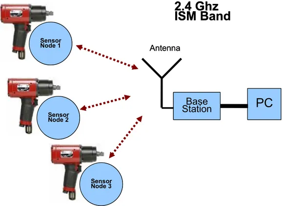
PC
Base Station Antenna2.4 Ghz
ISM Band
Sensor Node 1 Sensor Node 2 Sensor Node 3PC
Base Station Antenna2.4 Ghz
ISM Band
Sensor Node 1 Sensor Node 2 Sensor Node 3Figure 3: System Overview
On Figure 3, we can get a better picture of the system that is required. There are several tools which each one has a sensor node in it. The Base station communicates wireless to them and the information obtained by the Base Station is sent to the central computer (PC).
After discussing the main problems of this thesis work it is important to list these problems:
1. To design and develop a communication protocol which increases the battery life expectancy.
2. To develop a way of sensing the battery power.
3. To develop a way of sensing if the tool is on or off, and to be able to put on or off the tool.
4. To develop a GUI that can send and receive data from the BS.
5. To make correct calculations about the SN’s battery life expectancy.
1.4 Goal
The goal of this master thesis is to implement an active RFID system that can handle a couple of hundreds of active tags simultaneously. The system needs an appropriate power efficient communication protocol that allows the active tag’s battery to last at least 18 months. There was an already designed hardware but there was the possibility of changing it in order to increase the battery life expectancy.
Introduction
The second goal, which is not as important as the first one, is to sense and control a tool from a GUI. This means that the user can turn off the tool from the central computer, and will be able to read some variables like the tools working time, and be able to enable or disable the tool.
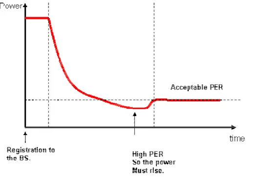
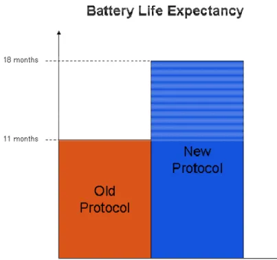
Figure 4: Protocol's battery life expectancy.
As shown in Figure 4, the previous protocol had a battery life expectancy of 11
months [1] and the new protocol should at least have a life expectancy of 18 months, this is considering a report period of 4 seconds. This means the new protocol’s battery life expectancy has to be 63% more than the old one.
1.5 Limitations
Is very important to specify the limitations of this master thesis, especially because it is such a big system there is a need to put some limits. This master thesis will not consider the EMC of the system. It will not consider the antennas design and their radiation patterns. Other physical phenomena will also be excluded like inductance, mutual inductance, field strength, etc.
Part of the hardware was proposed by me, but the PCB design was done by Björn Hilliges, and for that reason the PCB design will not be considered in this master thesis, but the reason for choosing the main components will be explain in detail. Due to the fact that empirical tests will take too much time, only small test can be done in order to prove that the system is working correctly. An empirical test of the battery lifetime will take around 2 years to really be sure it works; therefore that test will be excluded from the master thesis.
The RFID system will not be ready for the market because many tests need to be performed before we know the system is fully functional and no errors are detected, and those tests as I said before will not be performed in this thesis.
1.6 State of the art in Automatic Identification Systems
The main purpose of an AID System is to obtain information about people, animals, goods, and products. The systems are used mainly by the industry to give information about specific goods or services and it is important to know what type of systems are used nowadays to be able to notice the advantages of using RFID. The Barcode system has been used for the last 20 years and is the most known AID System, and the main advantage of this system is the cost, it is really cheap. The Barcode is starting to be inadequate because it has a low storage capacity and can not be reprogrammed. A Barcode system is used nowadays for example in the super market, where each item has a barcode, the system can distinguish between a box of cereal from a box of chocolate, but it cant identify the difference between to cereal boxes of the same type due to the low storage capacity problem. Another AID System is the optical character recognition; this system can recognize numbers that are printed in a special font that can be read by the system the same as humans do. The next types of AIDS are the biometric procedures, for example voice, fingerprinting and retina recognition. These readers are very expensive and are used only to identify people and the reading speed is very low.Another technique to identify people is the use of smart cards. There are many different types of smart cards; the most common ones are memory cards, and microprocessor cards. The drawback of these systems is that they need to have contact with the reader, and this makes the process a little bit slower in comparison with a wireless reading. The smart cards have the possibility to store and to exchange information with the reader.
RFID is also an AID System that does not need to have physical contact with the reader like a smart card system; it also does not need a line of sight like the bar code, making this system a lot more versatile. RFID systems are less expensive than biometric systems and the reading speed is much faster. There are mainly two types of RFID, passive and active. In passive RFID the reader sends power wirelessly to the tag, and the tag uses this power to send back an id in form of an electromagnetic wave. An active RFID system is slightly different because the tag has its own power supply. Active tags can store, process and exchange information and have a longer reading distance.
Nowadays, RFID systems are starting to be used in all kind of industries, soon we will reach a point where RFID tags are so cheap that every single product in the world will use them replacing the old barcode technique, is just a matter of time for this to happen. See [3] [4].
Introduction
1.7 Disposition
This thesis is divided into 10 chapters. Chapter one gives a brief introduction to the thesis, explains briefly what is RFID and what are some of the benefits of it. It also explains the problem that has to be solved and the goals of the thesis. Chapter two gives an introduction to wireless technology, explaining a little bit more deeply RFID systems and some of the standards and protocols. Chapter three provides a background to lithium batteries, what are their normal behaviors and some electrical characteristics. Chapter four shows the first analysis of the previous protocol that did not fulfill the battery lifetime expectations. In this chapter it is explained what were the main problems with the previous protocol and some proposals are made in order to improve the battery life expectancy. An extensive analysis of the battery lifetime is done in this chapter that leads to the final protocol design. Chapter five is the actual implementation which is divided into three main sections which are the protocol, the hardware and the software. Chapter six shows the results obtained in the thesis and compare the results with the actual thesis goals. Chapter seven shows the conclusion, chapter eight references and nine the appendixes.
2 Wireless Technology
Before starting the design of the new protocol it is important to describe the technology that is going to be used in this project. It is important to mention about radio communication, wireless sensor networks, RFID systems, and some existing protocols.
2.1 Radio Communication basics
2.1.1 Definitions
Carrier wave – It is a RF signal that carries information; it is usually of a much
more higher frequency than the information itself. It is normally a sinusoid wave.
Carrier wave frequency – It is the central frequency of the carrier wave. Bandwidth – Is the width of the range of frequencies in a signal.
Modulation – Is the technique is used to modify a signal in order to be able to send
it by radio waves, there are many types of modulations, some of the most important ones are AM, FM and PM.
• AM (Amplitude Modulation) – It is done by varying the amplitude of the carrier wave with respect of the amplitude of the information signal. For example TV (picture) uses this type of modulation.
• FM (Frequency Modulation) – It is done by varying the frequency of the carrier with respect of the amplitude of the information signal. For example TV audio uses this type of modulation.
• PM (Phase Modulation) – It is done by changing the phase of the carrier wave with respect of the amplitude of the information signal, this type of modulation is a little bit more complicated than AM or FM, specially the reception part.
• Digital Modulation – Is done by varying a carrier wave with respect of a finite and discreet signal. There are many techniques for modulating a digital signal for example ASK, FSK, GFSK, PGK, QAM. In this thesis project there will be a need to modulate a digital signal so it is important to know the different techniques to achieve this.
o ASK (Amplitude Shift Keying) – It is done by varying the amplitude, when a “1” is transmitted a fixed amplitude is transmitted and when a “0” is transmitted, no signal is transmitted.
o FSK (Frequency Shift Keying) - It is done by varying the frequency, and basically two frequencies are used, f0 and f1, f0 is used to transmit a “0” and f1 is used to transmit a “1”.
o GFSK (Gaussian Frequency Shift Keying) – Has the same principle of FSK but a “1” is a positive shift from the base frequency and a “0” is a negative shift from the base frequency.
o PSK (Phase Shift Keying) – Different phases represent different combinations of 0s and 1s.
Wireless Technology
o QAM (Quadrature Amplitude Modulation) – Combination of AM with PSK, and different combinations represent different sequences of 3 bits (8 different values).
2.2 Wireless Sensor Networks
Wireless sensor networks have very small and efficient power consumption nodes that transmit information from the environment. The information is sensed and sent wireless through the network to finally arrive to a management center where all the information is displayed. This information can then be analyzed and take appropriate decisions of what needs to be done. WSN can be used for example in monitoring temperature, pressure, moisture, pollution, sound, vibration, and many other variables that need to be known. An important aspect of a WSN is the power management, the network needs an appropriate protocol in order to take care about the energy consumption; this point is very important because a SN has a battery as a source of energy and needs to last as long as possible. In this part of the chapter it will be discussed some network configurations, protocols, and other important considerations about WSN. See [11].
2.2.1 Communication Networks 2.2.1.1 Network topology
There are different ways of connecting nodes in a network, some of the typical topologies are listed below and shown in Figure 5.
Fully connected topology – This network type suffer the problem that as more
nodes are added the number of connections increase exponentially, and this is the reason why large networks can simply not use this topology type.
Mesh topology – In this network type the nodes are connected to their nearest
neighbors, usually nodes are evenly spread, and are used to connect large networks. This topology type is very useful for WSN where the nodes are spread over a geographical area.
Star topology – all the nodes are connected to a hub, this hub has routing
capabilities and knows where it receives and where should send the data, if one of the connections is cut, the rest of the nodes will not be affected and that is a big advantage compared with the ring topology.
Figure 6: Self Healing Ring topology [11]
Ring topology – This topology is connected as it name indicates, in a ring, the
problem with this topology is that if one link is cut the whole communication is lost, this topology can be improved if a secondary ring is installed like a back up, so if the primary ring is lost the back up can be used. The name of this modified ring
topology is self healing ring topology and is shown in Figure 6. This type of
network has a lot of traffic because the information goes through many nodes before the information reaches the destiny.
Bus topology – Every node is connected to the same bus, the nodes will only pay
attention to messages that are sent to it, if the message is for another node, it will discharge it. No decisions are taken by the bus, only each node takes the decision of which packet to read.
Tree topology – There is a central “root” node where all the connections are
started. The nodes that are connected to this central node are also the “root” to other nodes.
2.2.2 Network Characteristics
Headers – Each packet that is transmitted through a network has a header. There
are many different types of headers but they normally have the same information. A header contains the source and destination address, the packet length, a protocol header, etc. The headers help the nodes to identify which packet should they read and which not and also helps to properly route a package to the final destination.
Switching – There are several types of switching techniques, one of the most used
techniques is “store and forward”, in this case the whole package is received and stored in the nodes local memory and then retransmitted to the next node. Another technique is called “wormhole”, in this technique the package is split up into smaller
Wireless Technology
pieces called flits, the header flit is send and the rest of the flits follow the header in a pipeline. Another technique is called “virtual cut-through”, and in this case the header is read but the node does not wait for the whole package, once it reads the header it forwards it to the destination.
Multiple access protocols – Networks nodes need to know some rules to avoid
collisions with other nodes and therefore loose data. These rules are called protocols. ALOHA is a simple protocol where a node sends a package and waits for an acknowledgement, if this acknowledgement does not arrives the node waits a random time and then retransmit again the package. This process will repeat until an acknowledgement arrives. This technique is good when there are not so many nodes or not so much data transfer between nodes, as the transmissions increase the network will be slower. There are other anti-collision procedures used in networks the most common are FDMA, CDMA, TDMA, and CSMA. In Frequency Domain Multiple Access (FDMA), different nodes have different carriers at different frequencies, in that way two nodes can transmit at the same time because they use different frequencies. In Code Domain Multiple Access (CDMA) every node has its own code; data is coded and decoded in every transmission and reception. This technique requires very complex transmitters and receivers. In Time Domain Multiple Access (TDMA) every node has its reserved “piece” of time to transmit, if a node has to send a package it has to wait for its time slot to be able to send the package. In Carrier Sense Multiple Access the node basically senses the carrier before talking if the carrier is used by another bye someone else the node will wait and transmit when the carrier is free.
Open Systems Interconnection Reference Model (OSI/RM) – This model was
created by the International Organization for Standardization. The model was created to make it easy to understand how communication networks and applications interact with each other and to be able to interconnect different types of networks and systems. The OSI model is divided into seven layers: Physical layer, Link layer, Network Layer, Transport Layer, Session Layer, Presentation layer, and Application Layer. The first three layers are the ones important to networks. The physical layer defines the hardware characteristics to connect networks. The Link layer handles error correction and flow control. Routing and more complex flow control are performed by the Network layer.
Routing – A distributed system usually has many nodes and deals with many
packages, therefore many decisions need to be made. It is important that these decisions are optimum to avoid unwanted conditions like deadlock or livelock. Dead lock is when for example all the memory in the nodes is full and therefore the nodes cannot receive any other package and also cannot send because the neighbor’s memory is also full. Livelock is when a package is going from node to node without reaching the final destination. The main performance measurements in a routing protocol are average package latency and throughput.
2.2.3 Power Management
One of the most important aspects that must be considered in WSN is the power management. Normally a sensor network has its own power supply, and this power supply is finite, therefore it has to take care of how it uses the available power. This
is why the generation, conservation and management of energy is an essential aspect that must be taken in consideration. There are systems that can generate and conserve power, for example systems that uses rechargeable batteries with solar panels. There are other systems like for example passive RFID where the energy is transmitted to the tag and the tag uses the same received energy to transmit its id up to 96 bits.
Proper selection of a communication protocol will increase the battery life expectancy of the whole WSN. A good technique used to save power is TDMA, it saves energy because the SN sleeps for a whole period and wakes up exactly in the time slot that needs to transmit or receive.
2.2.4 Applications
WSN have many varied commercial and industrial applications, and they are mainly used when cabled sensors are too expensive to install. Imagine that a forest wants to be monitored, to see how much moisture is in the air. It would be impossible to put wired sensors all over the forest and would affect the forest itself. It is easier to just put some self powered wireless sensors to do the same task. Some of the applications that WSN are listed below:
• Process Monitoring • Habitat monitoring • Acoustic detection • Military surveillance • Inventory tracking • Medical monitoring • Environmental monitoring • Smart spaces
• Structural health monitoring
2.3 RFID Systems
Radio Frequency Identification is a technique to identify an object in an automatic way using radio waves. The id of the object is a serial number that is transmitted wireless to a reader. An RFID system basically consists of a reader and several tags. There are 3 types of tags, passive, active and semi active. An RFID system can operate in different frequencies that go from 100 kHz up to 24 GHz. The reading range can go from 10 cm to 30 meters, depending on the application. The cost of a tag can go from € 0.06 to € 100.
2.3.1 Passive RFID tags
The main characteristic of a passive RFID tag is that it does not have a power supply. Actually it is fascinating the way a passive tag works because it gets its power wireless from the reader in order to be able to send its id. The reader sends energy
Wireless Technology
at a maximum power of 2W and then waits for the replay of the tag. The reading range of a passive tag goes from 10 cm to 6 meters. Passive RFID tags are very cheap € 0.06 but still not cheap enough to replace the bar code system. In the future when the price is reduced around € 0.015 every single product will have a passive tag and the bar code will disappear. Thanks to collision avoidance protocols a bunch of products in a bag can easily be read all together in a couple of mili seconds. It is estimated that passive tags will replace the bar code by the year 2013. See [3].
2.3.2 Active RFID tags
Active RFID tags can also be considered like sensor nodes. This type of tags have its own power supply, it can be a rechargeable battery, alkaline battery, or lithium battery. Active tags have a microcontroller, a RF chip, an antenna and battery. The reading range of an active tag can go from 10 cm to 30 meters. An active tag also has a serial number which is stored in program or data memory. Active tags can process information and are able to take decisions; that is why they can also be considered like sensor nodes. A very important aspect of active tags is the power management, it is important that the power modes of the microprocessor are used in a proper way in order to make the battery life as long as possible. See [3].
2.3.3 Semi Active RFID tags
Semi Active RFID tags is a combination between active and passive tags. This type of tags have also a battery and a microcontroller like the active ones but they don’t use the batteries energy to send the carrier wave, but it uses it to modulate the signal and also for the microcontroller. The battery life time in these systems can be longer than the active tags.
3 Battery Investigation
A battery has the property to change chemical to electrical energy; this energy can then be used by electronic systems to power up them. A battery consist of at least one voltaic cell, each cell consists of two half cells connected each other with a conductive electrolyte. Each cell consists of a positive and negative electrode, a positive electrode is known as the cathode and a negative electrode as the anode. The anode and the cathode are not connected to each other, but when a resistive load is connected to each of them a current will flow from the anode to the cathode. A classification of batteries separates them in two groups, primary and secondary batteries. Once the power of a primary battery finishes it can not be restored electrically, it can only be restored if the chemicals are changed. The secondary battery group characterizes for being able to be recharged by supplying electrical energy to the cell.
As the main goal of the master thesis is to have a longer battery life, an analysis of different types of batteries should be done. It is important to know why some batteries are better for different applications and what considerations should take when working with a certain type of battery.
3.1 Lithium Batteries
Lithium batteries are classified in the primary group, so they can not be recharged. These batteries can produce voltages from 1.5 to 3 volts and this is double that what a carbon-zinc battery or an alkaline can produce. Lithium or a lithium compound is used as an anode, and depending in this compound use it can produce different voltages.
Lithium Batteries are used in many long life critical devices like for example cardiac pacemakers that can last as long as 15 years.
3.2 Alkaline Batteries
An alkaline battery uses zinc powder as anode and Manganese dioxide (MnO2)
powder as a cathode. Alkaline batteries are also classified in the primary group.
3.3 Resume
It is important to choose the correct type of battery, as we can see in Table 1;
lithium batteries have almost three times more power than alkaline batteries. It is important to notice that an alkaline battery can give up to 1.5 volts and that will not be enough to satisfy the majority of small microcontrollers. The price of an alkaline battery is cheaper than a lithium battery, but considering that the lithium battery has almost three times more power then the total “power” cost is more expensive in the
Battery Investigation
alkaline one. After analyzing roughly some batteries characteristics we notice why lithium batteries are more used in WSN and active RFID tags.
Lithium Alkaline Operating
Temperature Range
-55° C to +200° C -20° C to +54° C
Energy Density 14.7 Wh/in3 / 900 Wh/L * 5.2 Wh/in3 / 320 Wh/L **
Nominal Voltage 3.9 V / 3.6 V 1.5 V
Watt Hours (for D size cell)
59.0 22.5
Advantages - Ideal in high shock and vibration environments
- Very high open circuit & nominal load voltages
- Lighter weight than alkaline (lower pack weight, easier field service, easier handling)
- Internally fused
- Possibly lower “total” cost
- Low unit cost - Easier to transport - Easier to dispose
Disadvantages Requires knowledge of appropriate safety and handling.
- Limited temperature range - Short life cycle
- Low power density per cell - Not hermetically sealed – potential leakage hazard - No internal safety fuse
Applications MWD/LWD
Pressure Measurement Pipeline Inspection Seismic Surveying Mobile Asset Tracking EPRIBS
Sonar Devices Fleet Management Electronic Toll Collection Automated Instrumentation Oceanographic Buoys Satellite Systems Surveillance Aerospace RFID & M2M GPS Systems Memory Backup Sensing Devices Cameras Electric shavers Electronic calculators Electronic door locks Fire detectors High-power flashlights Pagers Strobes Tape recorders Toys
Other cordless products
*Based on 3.3 average loaded voltage **Based on 1.2 average loaded voltage
4 Design options and decisions
4.1 Approach
It is important to mention that a system that was almost fully functioning was developed before. In this section the old system will be described and analyzed in order to get a better solution. After describing and analyzing the already existing protocol, some solutions will be discussed, and at the end of this chapter the chosen solution will be described roughly, but will be described more detailed in chapter 6. It is also important to mention that there was an already designed hardware but there were no restrictions to make a completely new implementation or to do just some small adjustments.
4.2 Old System
4.2.1 Old Protocol Description
The old protocol was designed by Joakim Gustafsson [1]. In this case the hardware was already designed so the protocol had to be based in the available hardware. It was a stochastic protocol, where every sensor node didn’t have a hard schedule, so the report periods where not exact and where not synchronized with the base station.
The system consists of two channels, one channel for the beacon signal and one channel for sensor nodes report, base station’s acknowledgement and data packages. The base station send one beacon packet as broadcast so all the sensor nodes can read the package, this package is sent every 12 ms and the main purpose of this package is to inform to the sensor nodes that the base station is near them and that they can communicate with it.
The sensor nodes had basically three modes; the first mode is the registration mode, when the sensor nodes are registered in the base station. The second mode is when the sensor node is out of the range of the base station (outside the network) and the third mode is when the sensor node is inside the range of the base station (inside the network).
When the sensor node is inside the range of the base station the sensor will send a report package telling the base station that the senor node is inside its range. The base station then acknowledges and sends the report period for the sensor node. After receiving this acknowledgement the sensor node will sleep the report period. When the sensor node wakes up, it will check if some other sensor node is sending a package, if not, it will try to send a report package, then it will receive an acknowledge package from the base station and the cycle starts again.
Decisions
If when the sensor node wakes up, it detects that someone else is using the channel, the sensor node will sleep a random time between 1-255 ms and then wake up and try to communicate again with the base station. If again the sensor node wakes up and the channel is still being used then the sensor node will sleep another random time and try to communicate finally with the base station.
When the sensor is outside the range of the base station, it will search for a beacon package every certain amount of time. So the sensor node sleeps a certain amount of time, then wakes up and is active for 12 ms trying to reach a beacon package. If it reads a beacon package then the sensor node will send a package to the base station and the whole cycle begins again.
There are some power features considered in the protocol. When the sensor node detects the beacon signal, it will register. After registration it will start transmitting a report package with the smallest possible output power. If the SN does not receives an acknowledgement it will transmit again with the same output power. If again the SN does not receive an acknowledgement it will raise the output power. This will happen 4 times and if no acknowledgement is received then the SN will change to outside of network mode.
There is a much more detailed explanation about this protocol in Joakim Gustafsson thesis report [1].
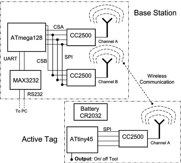
4.2.2 Old System Hardware
The old hardware consists of one Base Station and 254 sensor nodes. The Base Station consists of two RF chip CC2500, two antennas, one ATmega128 and one Max3232, and the 254 sensor nodes (active tags) consists each node in one ATtiny45, one battery CR2032, one radio chip CC2500 and one on-PCB antenna. In both, the Base Station and the sensor nodes (active tags) the interrupt pins of the
CC2500 were not connected to the microcontroller. Figure 7 shows the old
hardware. The ATmega1281 microcontroller is connected to a PC through a RS232 interface. All the user commands are sent from the PC to the BS through the RS232. The two CC2500 Radio Chips are connected in the same SPI port; each chip will use a different frequency channel. The SNs ATtiny84 microcontroller is connected through a SPI to the CC2500 Radio Chip. Both the SN and the BS communicate wirelessly using the CC2500 Radio chips.
ATmega128 CC2500 CC2500 SPI MAX3232 RS232 UART To PC Channel B Channel A CSA CSB ATtiny45 CC2500
Output: On/ off Tool
Channel A SPI Wireless Communication
Active Tag
Base Station
Battery CR2032 ATmega128 CC2500 CC2500 SPI MAX3232 RS232 UART To PC Channel B Channel A CSA CSB ATtiny45 CC2500Output: On/ off Tool
Channel A SPI Wireless Communication
Active Tag
Base Station
Battery CR2032Figure 7: Old System Hardware.
The most important change of the new hardware should be to connect the CC2500 interrupt pins to the microcontroller, in that way the microcontroller can detect an event form the CC2500 exactly when it happens, and don’t need to wait unnecessary time to attend any petition.
4.2.3 Old System Software
The old software in the BS was a Cyclic Executive Schedule and that presented some problems when talking about power. The round consisted on basically two tasks:
1. Check if there is an incoming packet from the RS232. 2. Check if there is a packet coming from the CC2500.
If a packet from the RS232 was received, the microcontroller will immediately attend the packet command, and it will not pay attention to the CC2500 for some time. If at the same time a report packet was sent from a SN, the SN will have to wait the normal processing time of the microcontroller plus the processing time of
Decisions
the RS232 command, so the software was not optimized for the SNs power consumption because the SN had to wait for a longer time in RX mode.
As said before in the Old Hardware section, one of the most important changes should be to connect the CC2500 pin interrupts to the microcontroller in that way the software could be interrupt driven instead of a Cyclic Executive Schedule. If we consider the last example but now with the CC2500 pins connected, the SN would not have to wait so much time. The microcontroller reads the RS232 packet and starts processing the command, suddenly a packet from the CC2500 arrives and is detected in the interrupt pins, the microcontroller will stop whatever it was processing and go to the ISR and send an acknowledgement to the SN as soon as possible so the SN do not have to wait in RX mode, in this way we can save a considerable amount of energy in the SNs.
4.2.4 Old Protocols results
The battery lifetime calculation was done considering several factors. These factors were the range between the base station and the tag, reporting interval, output power, and the number of SNs in the system. Here are the factors used to calculate the battery lifetime.
• Number of SNs: 250
• Reporting interval: 8 seconds
• Two different channels for beacon signals • 12 ms beacon signal interval.
• 250 kbps data rate with PER 1%. • Time outside the container (25%) • Time inside the container (75%) • Beacon search 30 seconds.
The result of the battery life expectancy was of 11.1 months.
The reading range was of 25 meters, this was tested indoors in a long hallway but future tests should be performed outdoors in a large field to avoid EM reflections. The anti-collision feature could not be tested since only two tags were manufactured.
4.2.5 Old Protocol Analysis
The first thing that was detected is that the most expensive part of the protocol, talking about energy consumption, was when the sensor node was outside the base stations range. Let’s compare one report cycle inside the network and one outside the network. Let’s consider a 4 seconds interval. In this part of the analysis some parts of the Radio Chip states where omitted because in this point of the study this states where unknown but as the thesis was developed they where discovered. These
states will be considered in the final analysis in the results chapter. The unconsidered states were, Cristal Oscillator Stabilization (first thing that happens when the RC chip wakes up) this takes around 350 µs, Calibration that should not be done very often and takes 809 µs, and finally RC oscillator calibration which takes 150 µs. In the old protocol the Calibration was done every 4 period (Rx or Tx). Active Time:
∑
∑
= + + = + + = ms s s s T T T T T active CC RC n Calibratio XTALwakeup active CC 309 . 1 150 809 350 2500 2500 µ µ µThe different behavior analysis of the SN will use the following data (current consumption in different modes) in order to calculate the total current consumption.
Current consumption in different states or modes
• Radio Chips Tx output power (max) 21.6 mA. • Radio Chips Rx output power (min) 15.6 mA. • Radio Chip at Sleep mode 0.0004 mA.
• Radio Chip changing from Tx to Rx 8.5 mA. • Microcontroller Sleep mode 0.004 mA. • Microcontroller Active mode 2.5 mA.
The following analysis for the SN outside Network behavior was made considering that the SN will never find a beacon signal and that is why the SN has to search for 12 ms (BS beacon period).
SN Outside Network behavior
• 4000 ms report interval (100%) • 3988 ms sleep time (99.7%)
• 12 ms searching for beacon (0.3%).
Calculations: Time percentage: % 0044 . 0 100 4000 12 100 % % 7 . 99 100 4000 3988 100 % % 100 % Re Re Re = × = × = = × = × = = ms ms Time Time Time ms ms Time Time Time Time port Beacon Beacon port Sleep Sleep port
Decisions Average current: mA mA mA I I AvgI mA mA mA I I AvgI e CActiveMod RX CC Beacon CSleepMode e Sleep CC Sleep 1 . 18 5 . 2 6 . 15 0044 . 0 004 . 0 0004 . 0 2500 mod 2500 = + = + = = + = + = µ µ
The Average Current for the total report interval should be calculated considering the current consumption in different states (ex. Rx, sleep, etc) and also considering the active time of those states as follows:
(
)
(
)
(
0.997 0.0044) (
0.003 18.1) (
0.0043868mA) (
0.0543mA)
0.05869mA % % Re = + = × + × = × + × = mA mA AvgI Time AvgI TimeAvgI port Sleep Sleep Beacon Beacon
Charge:
(
)
(
)
(
)
(
Time AvgI)
H(
)
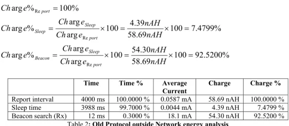
H nAHe Ch nAH H H AvgI Time e Ch nAH H H AvgI e Ch Beacon Beacon Beacon Sleep Sleep Sleep port port 30 . 54 1 0543 . 0 1 % arg 39 . 4 1 004386 . 0 1 % arg 69 . 58 1 0.05869mA 1 arg Re Re = × = × × = = × = × × = = × = × = Charge percentage: % 5200 . 92 100 69 . 58 30 . 54 100 arg arg % arg % 4799 . 7 100 69 . 58 39 . 4 100 arg arg % arg % 100 % arg Re Re Re = × = × = = × = × = = nAH nAH e Ch e Ch e Ch nAH nAH e Ch e Ch e Ch e Ch port Sleep Beacon port Sleep Sleep port
Time Time % Average
Current Charge Charge % Report interval 4000 ms 100.0000 % 0.0587 mA 58.69 nAH 100.0000 % Sleep time 3988 ms 99.7000 % 0.0044 mA 4.39 nAH 7.4799 % Beacon search (Rx) 12 ms 0.3000 % 18.1 mA 54.30 nAH 92.5200 %
Table 2: Old Protocol outside Network energy analysis
The following analysis is considering that the BS will receive the SN report package in the first attempt, and that the SN will receive the BS's acknowledgment also in the first attempt with only considering the delay from Tx to Rx (0.021 ms).
SN Inside Network behavior
• 4000 ms report interval (100%) • 3998.86 ms Sleep time (99.9647%) • 0.696 ms Transmission time (0.0174%) • 0.021 ms change from Tx to Rx (0.0005%) • 0.696 ms Reception time (0.0174%)
Calculations: Time percentage: % 0174 . 0 100 4000 696 . 0 100 % % 0005 . 0 100 4000 021 . 0 100 % % 0174 . 0 100 4000 696 . 0 100 % % 9647 . 99 100 4000 587 . 3998 100 % % 100 % Re Re Re Re Re = × = × = = × = × = = × = × = = × = × = = ms ms Time Time Time ms ms Time Time Time ms ms Time Time Time ms ms Time Time Time Time port Rx Rx port TxtoRx TxtoRx port Tx Tx port Beacon Sleep port Average current: mA mA mA I I AvgI mA mA mA I I AvgI mA mA mA I I AvgI mA mA mA I I AvgI e CActiveMod Rx CC Tx e CActiveMod TxtoRx CC TxtoRx e CActiveMod Tx CC Tx CSleepMode e Sleep CC Sleep 1 . 18 5 . 2 6 . 15 11 5 . 2 5 . 8 1 . 24 5 . 2 6 . 21 0044 . 0 004 . 0 0004 . 0 2500 2500 2500 mod 2500 = + = + = = + = + = = + = + = = + = + = µ µ µ µ
(
)
(
)
(
) (
)
(
) (
) (
) (
)
(
0.004398mA) (
0.004193mA) (
0.000055mA) (
0.003149mA)
0.011795mA 1 . 18 0174 . 0 11 0005 . 0 1 . 24 0174 . 0 0044 . 0 999647 . 0 % % % % Re = + + + = × + × + × + × = × + × + × + × = mA mA mA mA AvgI Time AvgI Time AvgI Time AvgI Time AvgI Rx Rx TxtoRx TxtoRx Tx Tx Sleep Sleep port Charge:(
)
(
)
(
)
(
)
(
)
(
)
(
)
(
Time AvgI)
H(
)
H nAHe Ch nAH H H AvgI Time e Ch nAH H H AvgI Time e Ch nAH H H AvgI Time e Ch nAH H H AvgI e Ch Rx Rx Rx TxtoRx TxtoRx TxtoRx Tx Tx Tx Sleep Sleep Sleep port port 15 . 3 1 0.003149mA 1 % arg 06 . 0 1 0.000055mA 1 % arg 19 . 4 1 0.004193mA 1 % arg 40 . 4 1 0.004398mA 1 % arg 80 . 11 1 0.011795mA 1 arg Re Re = × = × × = = × = × × = = × = × × = = × = × × = = × = × =
Decisions Charge percentage: % 6949 . 26 100 80 . 11 15 . 3 100 arg arg % arg % 5084 . 0 100 80 . 11 06 . 0 100 arg arg % arg % 5084 . 35 100 80 . 11 19 . 4 100 arg arg % arg % 2881 . 37 100 80 . 11 40 . 4 100 arg arg % arg % 100 % arg Re Re Re Re Re = × = × = = × = × = = × = × = = × = × = = nAH nAH e Ch e Ch e Ch nAH nAH e Ch e Ch e Ch nAH nAH e Ch e Ch e Ch nAH nAH e Ch e Ch e Ch e Ch port Rx Rx port TxtoRx TxtoRx port Tx Tx port Sleep Sleep port
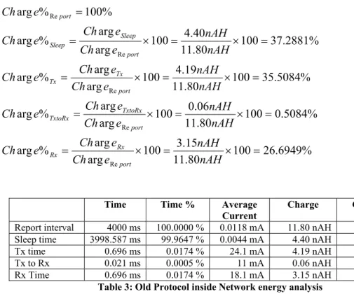
Time Time % Average
Current Charge Charge %
Report interval 4000 ms 100.0000 % 0.0118 mA 11.80 nAH 100.0000 % Sleep time 3998.587 ms 99.9647 % 0.0044 mA 4.40 nAH 37.2881 % Tx time 0.696 ms 0.0174 % 24.1 mA 4.19 nAH 35.5084 % Tx to Rx 0.021 ms 0.0005 % 11 mA 0.06 nAH 0.5084 % Rx Time 0.696 ms 0.0174 % 18.1 mA 3.15 nAH 26.6949 %
Table 3: Old Protocol inside Network energy analysis
Table 4 shows a resume of the SN behaviors, the values presented were calculated as follows: Time percentage: % 50 100 8000 4000 100 % % 50 100 8000 4000 100 % % 100 % = × = × = = × = × = = ms ms Time Time Time ms ms Time Time Time Time Total Inside Inside Total Outside Outside Total Average current: mA AvgI mA AvgI Inside Outside 0118 . 0 0587 . 0 = =
(
) (
)
(
0.5 0.0587) (
0.5 0.0118)
0.03525 A % % m mA mA AvgI Time AvgI TimeAvgITotal Outside Outside Inside Inside = × + × = × + × =
Charge: nAH e Ch nAH e Ch nAH e Ch Total Inside Outside 49 . 70 arg 80 . 11 arg 69 . 58 arg = = = Charge percentage: % 7400 . 16 100 49 . 70 80 . 11 100 arg arg % arg % 2600 . 83 100 49 . 70 69 . 58 100 arg arg % arg % 100 % arg = × = × = = × = × = = nAH nAH e Ch e Ch e Ch nAH nAH e Ch e Ch e Ch e Ch Total Inside Inside Total Outside Outside Total Time Time % Average Current Charge Charge % Outside 4000 ms 50 % 0.0587 mA 58.69 nAH 83.2600 % Inside 4000 ms 50 % 0.0118 mA 11.80 nAH 16.7400 % Total 8000 ms 100 % 0.0353 mA 70.49 nAH 100.0000 %
Table 4: Old Protocol energy analysis resume
1. The first thing we can notice is that the outside behavior of the sensor network is 4.97 times more expensive (in terms of energy consumption) than the behavior inside the network even that outside the network it does not transmit any information. In theory the outside behavior should be a lot less expensive (energy consumption) than the inside behavior because the processor and radio chip have a lot more things to do inside the network than outside, so the first thing to try to change is the beacon search (Rx) energy consumption. The only way of reducing the energy consumption is reducing the Beacon search time.
2. The protocol had another big problem, the MCU of the base station had to attend two different but important things concurrently, the beacon signal and the acknowledgement packages. If both things are needed to do at the same time, what is more important to do first? Transmit the beacon or transmit the acknowledgement package? If the beacon is delayed then a sensor node that was searching for a beacon package possible could not get the package because it was too late or would have to spend more time searching for the beacon. But if the acknowledgement package is delayed then the package that is waiting for the acknowledgement has to wait longer time in Rx mode and this represents more energy consumption. So both activities are important, beacon and acknowledgement packages, and should be done exactly at the same time, without delay.
Decisions
3. Another problem that this protocol presented was that the report intervals could not be very precise because of the random times it uses. For example, lets consider a report period of 4000 ms. Imagine that a tag wakes up exactly when it has to send the report package but it notices that the channel is being used, then it has to wait a random time between 1- and 256 ms, imagine that this random time is 200 ms, but again the channel is being used by another tag then it will have to wait another random time, imagine 240 ms. Then instead of sending the report every exactly every 4000 ms it will have a delay of 440 ms. So what should happen in this 440 ms? Should the base station affirm that the sensor node is missing or it is just delayed? Can the base station confirm that the sensor node was stolen or was taken out of the network?
4. Another problem with the old protocol was that there were no synchronization tasks to synchronize the clock of the sensor node with the clock of the base station, this could lead to problems for the base station when it has to decide if the tags are still in the range (in the network) or they are out.
4.3 First Protocol Solution
4.3.1 Protocol Description
The main goal of the protocol is to reduce the energy consumption of the network sensors. So the first thing that had to change was the beacon package period, instead of being every 12 ms, sends one package after another with no delay between packages. If the beacon takes 0.6 ms then the beacon search period would be double that time, around 1.2 ms, this is a reduction of 90 % of the time that the sensor node has to search for the beacon and therefore a huge reduction of energy consumption outside the network.
Old Protocol time Beacon Search 12ms Beacon Tx0.6ms Beacon New Protocol time Beacon Search 1.2ms Beacon Tx0.6ms Beacon
![Figure 1: SafeTool’s System [2]](https://thumb-eu.123doks.com/thumbv2/5dokorg/4630205.119700/22.918.205.716.567.864/figure-safetool-s-system.webp)
![Table 1: Lithium and Alkaline batteries comparison [10]](https://thumb-eu.123doks.com/thumbv2/5dokorg/4630205.119700/36.918.147.770.173.855/table-lithium-and-alkaline-batteries-comparison.webp)