Guidelines for UML or SysML modelling
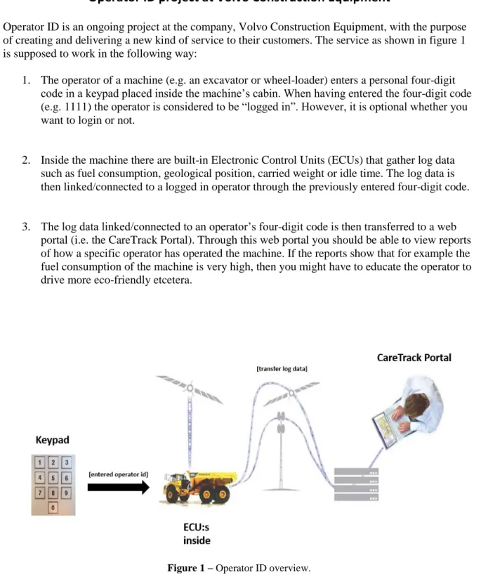
within an enterprise architecture
Mälardalen University
Academy of Innovation, Design and Technology Author: Charlie Höglund
Email: chd13002@student.mdh.se
Bachelor of Science in Computer Science/ Basic level, 15hp Date: 2017-06-08
Examiner: Jan Carlson
Supervisor: Daniel Sundmark
Abstract
Enterprise Architectures (EA) are used to describe an enterprise’s structure in a standardized way. An Enterprise Architecture also provides decision-support when choosing a direction or making changes at different levels of an enterprise, such as the business architecture or technology architecture level. This can involve decisions such as: What kind of enterprise should this be, what kind of technologies should be used for new system developments etcetera. Therefore, using the Unified Modelling Language (UML) or Systems Modelling Language (SysML) together with standardized guidelines that help you decide what to do before, during, and after modelling could be important for producing correct and useful system models, which later on will be used to develop actual systems. At the moment, standardized guidelines of this kind do not really exist. However, there are a lot of information about why you should use UML or SysML, what kinds of UML or SysML diagrams that exist, or what notations to follow when creating a specific UML or SysML diagram.
In this thesis, the objective has been to research about the usefulness and creation of standardized guidelines for UML or SysML modelling in an Enterprise Architecture (i.e. mainly intended for the automotive industry domain). For this reason, the two research questions: “how can you create useful standardized guidelines for UML or SysML
modelling?” and “what do useful standardized guidelines for UML or SysML modelling look like?” were chosen. A case study was performed on a real-life project at the company Volvo Construction Equipment, which resulted in the two research questions being answered. Firstly, a three-step method (i.e. create guidelines – test guidelines – improve guidelines) was proven to create useful standardized guidelines. Secondly, useful standardized guidelines were created from this three-step method. Hopefully, these created standardized guidelines can be used by the targeted companies right away to make their modelling work more efficient, or serve as a foundation when creating their own standardized guidelines later on.
Contents
1. Introduction ... 4 2. Background ... 4 2.1 Enterprise architecture ... 4 2.2 UML ... 5 2.3 SysML ... 6 2.4 Requirements ... 7 2.5 Scope ... 8 2.6 Business case ... 8 2.7 Software engineering ... 92.8 Systems engineering and Model-based systems engineering ... 9
3. Related Work ... 10
3.1 Teaching UML and SysML modelling ... 10
3.2 SysML for modelling embedded systems ... 10
3.3 Motivation in correlation to employee work performance ... 11
3.4 Importance of software documentation quality ... 12
3.5 Important software documentation artefacts for system maintainers ... 13
3.6 Essential UML diagrams ... 13
3.7 Video tutorials for learning how to use new software applications ... 13
3.8 How to store and manage computer files ... 13
4. Problem Formulation ... 14
5. Method ... 15
6. Ethical and Societal Considerations ... 16
7. The actual work process ... 16
8. Results ... 20
9. Analysis and Discussion ... 22
10. Conclusions ... 27 11. Future Work ... 27 References ... 28 Appendices ... 30 Appendix A ... 30 Appendix B ... 31 Appendix C ... 31
Figures
Figure 1 - UML diagrams. ... 6
Figure 2 - SysML diagrams. ... 7
Tables
Table 1 – Changes made to the initial standardized guidelines of the before modelling stage. ... 17Table 2 – Changes and tests made to the initial standardized guidelines of the during modelling stage. ... 19
Table 3 – Tests made to the initial standardized guidelines of the after modelling stage. ... 20
1. Introduction
The concept of Enterprise Architecture (EA) has today become increasingly common within enterprises and aims to describe an enterprise’s structure in a standardized way. Having an enterprise architecture makes it easier to understand how decisions made in one domain affect the other domains inside an enterprise, and thereby increases the enterprise’s pro-activity and efficiency. Within an enterprise architecture, using modelling technologies such as the Unified Modelling Language (UML) or Systems Modelling Language (SysML) along with standardized guidelines can also be important to achieve useful system models, which later on will be used to develop the actual systems. At the moment, standardized guidelines that tell you what to do before, during and after UML or SysML modelling do not really exist. The existing information of today is more about why you should use UML or SysML, what kinds of UML or SysML diagrams that are available, what perspective of a system that the specific UML or SysML diagram captures, what notations or rules to follow when creating the
specific UML or SysML diagram, when in a project’s process you should do UML or SysML modelling etcetera. Therefore, the objective of this thesis revolves around researching about the usefulness and creation of standardized guidelines for modelling technologies in an enterprise architecture, mainly to be used in the automotive industry domain. By having these standardized guidelines, you can for example produce system models that make sure to meet an automotive industrial company’s special needs but also enables higher scalability,
performance and maintainability for systems created from them.
2. Background
In this background section, you can read information about enterprise architecture, UML, SysML, requirements, scope (i.e. what does it mean), business case, software engineering, systems engineering, and model-based systems engineering.
2.1 Enterprise architecture
To clarify the meaning of an enterprise architecture, we must know the definition of the two individual words enterprise and architecture. Graves defines the word enterprise as:
[…] an organisation or cross-functional entity supporting a defined business scope or mission. It includes interdependent resources – people, organisations and technology – who must co-ordinate their functions and share information in support of a common mission or set of related missions. [1, pp. 9]
Furthermore, Graves defines the word architecture as “the structure of components, their interrelationships, and the principles and guidelines governing their evolution and design” [1, pp. 10]. Lastly, Graves combines these two definitions and defines an enterprise architecture as:
[…] a discipline through which an enterprise can identify, develop and manage its knowledge of its purpose, its structure and itself. Some of that knowledge will be about IT, but it will also need to include many other concerns: business architecture, organisational structure, performance management, business continuity/resilience planning, process architecture, security architecture, data architecture, applications architecture, technology – infrastructure architecture. [1, pp. 10]
Approximately twenty years ago, people began to notice that the cost and complexity of IT systems increased exponentially, while the chances of actually getting real value from those IT systems dramatically decreased. Thus, the field of enterprise architecture was introduced to address these issues and instead reduce the IT cost and complexity, while increasing business value and effectiveness [2]. Furthermore, Graves [1] mentions that the purpose of an
enterprise architecture is to provide decision-support when choosing a direction or making changes at any level of an enterprise (e.g. at the business architecture or technology
architecture level). This includes decisions such as: What kind of enterprise should this be and what should it do, what technologies should be used for new system developments, and how should we integrate a newly acquired system with our own existing system. By having a clear structure and support for making decisions within an enterprise’s different levels, an
enterprise architecture can also assist in managing changes or demands from the outside customers, market and new regulations [1, pp. 11-12]. This will improve an enterprise’s competitiveness against other enterprises. Graves also writes that ”a more mature enterprise architecture will be able to map interdependencies across almost every aspect of the
enterprise” [1, pp. 12], which implies that an enterprise architecture makes it possible to see how a decision or change at one level affects the other levels. This could for example be how updating a software application would increase the work efficiency of the employees at an enterprise.
2.2 UML
The Unified Modelling Language (UML) is a general-purpose modelling language created by the Object Management Group (OMG) which is an international, open membership, not-for-profit technology standards consortium. The following relevant information is written at UML’s official website:
Modeling is the designing of software applications before coding. Modeling is an essential part of large software projects, and helpful to medium and even small projects as well. A model plays the analogous role in software development that blueprints and other plans (site maps, elevations, physical models) play in the building of a skyscraper. Using a model, those responsible for a software development project's success can assure themselves that business functionality is complete and correct, end-user needs are met, and program design supports requirements for scalability, robustness, security, extendibility, and other characteristics, before implementation in code renders changes difficult and expensive to make. […] You can use UML for business modeling and modeling of other non-software systems too. [3]
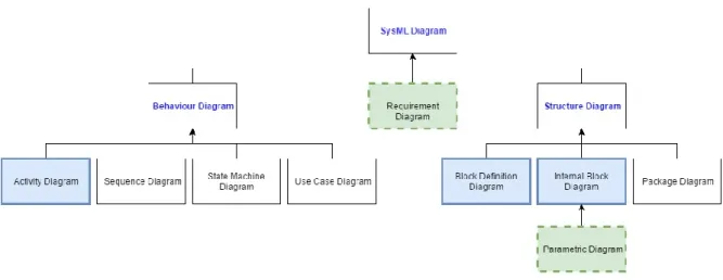
Furthermore, UML 2 (i.e. the latest version) consists of thirteen different diagrams that are divided into three categories (figure 1). The first category is structure diagrams that represent static application structure and includes the class diagram, object diagram, component
diagram, composite structure diagram, package diagram, and deployment diagram. The second category is behaviour diagrams that represent general types of behaviour and includes the use case diagram, activity diagram, and state machine diagram. The third category is interaction diagrams that represent different aspects of interactions and includes the sequence diagram, communication diagram, timing diagram, and interaction overview diagram (i.e. all derived from a general behaviour diagram). [3]
Figure 1 - UML diagrams.
2.3 SysML
The Systems Modelling Language (SysML) is a general-purpose modelling language derived from UML and created by the Object Management Group. The following relevant
information is written at OMG SysML’s official website:
The OMG Systems Modeling Language (OMG SysML) is a general-purpose graphical modeling language for specifying, analyzing, designing, and verifying complex systems that may include hardware, software, information, personnel, procedures, and facilities. In particular, the language provides graphical representations with a semantic foundation for modeling system requirements, behavior, structure, and parametrics, which is used to integrate with other engineering analysis models. It represents a subset of UML 2 with extensions needed to satisfy the requirements of the UML for Systems Engineering RFP. […] The UML for Systems Engineering RFP was developed jointly by the OMG and the International Council on Systems Engineering (INCOSE) and issued by the OMG in March 2003. […] The RFP specified the requirements for extending UML to support the needs of the systems engineering community. [4]
SysML consists of nine different diagrams as shown in figure 2, where eight of them are divided into two categories and the last diagram is categorized as a general SysML diagram. The first category is structure diagrams that includes the following diagrams:
A block definition diagram describes the system hierarchy and system/component classifications. The internal block diagram describes the internal structure of a system in terms of its parts, ports, and connectors. The package diagram is used to organize the model. […] The parametric diagram represents constraints on system property values such as performance, reliability, and mass
properties, and serves as a means to integrate the specification and design models with engineering analysis models. [4]
The second category is behaviour diagrams that includes the following diagrams:
A use case diagram provides a high-level description of functionality that is achieved through interaction among systems or system parts. The activity diagram represents the flow of data and control between activities. A sequence diagram represents the interaction between collaborating parts of a system. The state machine diagram describes the state transitions and actions that a system or its parts perform in response to events. [4]
Lastly, the final diagram categorized as a general SysML diagram is the following:
The requirements diagram captures requirements hierarchies and requirements derivation, and the satisfy and verify relationships allow a modeler to relate a requirement to a model element that satisfies or verifies the requirements. [4]
Figure 2 - SysML diagrams.
2.4 Requirements
Requirements are the descriptions of what the system should be able to do, which are based on the different needs and demands of the involved stakeholders such as system customers or end-users. To collect, analyse and document these requirements you can follow the process called requirements engineering (RE) [5, pp. 83], which includes the following four main activities: Doing a feasibility study where you investigate whether or not to go through with creating a system based on its possibility to actually meet the stakeholders’ needs with current software and hardware technologies, if the system can be created within the existing budget constraints and return a profit etcetera. Doing a requirements elicitation and analysis where you obtain the system’s requirements through for example discussions with potential
customers or end-users about their needs, and observations of existing systems’ constraints on the new system. Doing a requirements specification where you create a standard form
document containing all of the gathered requirements. Doing a requirements validation to check that the gathered requirements are actually correct according to the stakeholders such as system customers or end-users [5, pp. 37-38].
Requirements can be of two different levels: User requirements that are high-level descriptions of what services the system is supposed to provide to its end-users, and the constraints put on the system under its runtime. System requirements that are detailed descriptions of the system’s services, functions and runtime constraints (i.e. what is to be implemented). These two levels of requirements are useful since they describe the same system in a way that is understandable or necessary for different kinds of readers. The user requirements should be readable for people with less detailed technical knowledge, such as system customers or end-users, to get a general idea of what the system’s services and constraints are. However, the system requirements are usually read by the more technical people, such as system and software engineers, to get a starting point of what to implement and what the system design should be like [5, pp. 83-84].
Requirements of a software system are commonly categorized as either functional requirements or non-functional requirements, which in turn can be expressed as user
requirements or system requirements. The functional requirements describe what the system should or should not do, for example how the system reacts to particular input or what outputs the system generates. The non-functional requirements describe what the system should be like, for example that the system should have high reliability, availability, security or response time [5, pp. 84-87].
The software requirements specification (SRS) is a document that contains information about what the system developers should implement. This document should include both the high-level user requirements and the detailed-high-level system requirements. Here it is important that the user and system requirements are easy to understand, unambiguous, complete and consistent [5, pp. 91-94].
2.5 Scope
A project can be defined as temporary work that is going to be done within a chosen time frame, where you aim to create something of value such as a product or service. The project’s end is reached when the “objectives have been achieved or when the project is terminated because its objectives will not or cannot be met, or when the need for the project no longer exist”. Furthermore, a project can also be terminated “if the client (customer, sponsor, or champion) wishes to terminate the project” [6, pp. 3].
When having a project, you need to define its scope (i.e. the boundaries of the project) which consists of a product scope and project scope. But before defining the product scope and project scope, you have to collect and document the stakeholders’ (e.g. system customer or end-user) different needs and requirements, which provide a basis when specifying the scope [6, pp. 110]. The product scope specifies “the features and functions that characterize a product, service, or result” that will be created. The project scope specifies “the work performed to deliver a product, service, or result with the specified features and functions”. Having a clear scope simply allows you to know what is and is not included in the project [6, pp. 105].
2.6 Business case
Before starting up a project, it is common to do a feasibility study where you assess whether it is worth to go through with the project or not [5, pp. 37]. With the feasibility study, you mainly analyse the required cost and value to be obtained (i.e. it is profitable if you can earn
more than what you spend; be it for example financial growth or higher customer
satisfaction). The gathered information from the feasibility study can then be summarized in a business case. A business case is basically an argument for convincing decision makers to approve “a particular course of action for the organisation, supported by an analysis of
benefits, costs and risks” [7, pp. 10]. The business case could for example be used to motivate why a project or investment should be made. Furthermore, business cases are usually
presented in well-structured spreadsheets or documents that clearly show the benefits, costs and possible risks.
2.7 Software engineering
Sommerville defines software engineering as “an engineering discipline that is concerned with all aspects of software production” [5, pp. 6]. In software engineering, you use so-called software processes to systematically produce a software product. A software process is simply a set of sequential activities from the start to end of production. According to Sommerville [5, pp. 9], a software process consists of the following four activities: Software specification, where you define the different functionalities of the software to be produced and its operational constraints (e.g. with help from the customers and engineers). Software
development, where you design and produce the actual software. Software validation, where you verify and validate that the produced software functions as it is supposed to do (i.e. fulfils the customers’ requirements). Software evolution, where you update the up-and-running software to meet changing requirements of the customers or market. These four activities also include their own sub-activities such as requirements elicitation and architectural design etcetera.
2.8 Systems engineering and Model-based systems engineering
According to Sommerville [5] systems engineering consists of “procuring, specifying, designing, implementing, validating, deploying, operating, and maintaining” systems (i.e. sociotechnical systems that include software, hardware and interactions with people and its environment). In systems engineering you involve people with different professions such as software engineers, electronic engineers, mechanical engineers and user-interface designers, to create systems that meet today’s standards and needs (e.g. imagine an anti-lock braking system (ABS) for cars). Sommerville also mentions that system procurement, system development and system operation are the fundamental processes in systems engineering. Sommerville describes these three processes as overlapping stages in the following way:
1. Procurement or acquisition - During this stage, the purpose of a system is decided; high-level system requirements are established; decisions are made on how functionality will be
distributed across hardware, software, and people; and the components that will make up the system are purchased.
2. Development - During this stage, the system is developed. Development processes include all of the activities involved in system development such as requirements definition, system design, hardware and software engineering, system integration, and testing. Operational processes are defined and the training courses for system users are designed.
3. Operation - At this stage, the system is deployed, users are trained, and the system is brought into use. The planned operational processes usually then have to change to reflect the real working environment where the system is used. Over time, the system evolves as new
requirements are identified. Eventually, the system declines in value and it is decommissioned and replaced. [5, p. 273]
Model-based systems engineering is a variant of systems engineering. It uses systems modelling to support the systems engineering processes system procurement, system
development and system operation [8]. In the past it was more common to use documents for exchanging information between engineers, but with model-based systems engineering you mainly use system models as the source of exchanging information. Using system models (e.g. UML or SysML diagrams) makes it easier to capture, visualize and analyse the system’s requirements and what their relationships are, knowing what system to implement and what to expect from it, how adding new requirements or functionalities may affect the already
operational system etcetera.
3. Related Work
In this related work section, you can read about other relevant research that have been made.
3.1 Teaching UML and SysML modelling
Kruus et al. [9] write that systems need to be carefully modelled before being developed, in order to decrease the risks of failure. In their paper, they address the issues of teaching UML and SysML modelling to computer and systems engineering students, together with the problems encountered. Here they mention that the necessary systems modelling skills for modelling complex software and hardware systems cannot be taught at once, but instead need to be evolved over a longer period of time and practice. A few of the problems encountered by the students was being able to capture and model functionality through use case diagrams, and making valid relationships between classes/blocks in class/block definition diagrams, which was due to poor imagination, laziness, or too little practice. Furthermore, some of the students concluded that it is necessary to thoroughly model a system before actually coding it, since it decreases the chances of having to rewrite the code because of small mistakes. This tells us that the people given the role of being a systems modeller need to have evolved their modelling skills over a longer time period, to be able to create UML or SysML diagrams that are more useful and correct. Otherwise if the systems modeller has had non or very little practice in UML or SysML modelling, the diagrams will most likely be faulty and incorrect.
3.2 SysML for modelling embedded systems
Ouerdi et al. [10] have made a study about whether UML or SysML is most appropriate for modelling embedded systems, which in their case was a cellular phone. In this study, they concluded that SysML is more suitable than UML for modelling embedded systems since it provides the possibility to model hardware architecture, environment and security needs. Furthermore, SysML also enables you to better model the link between software and
hardware compared to UML, which gives you a much clearer overview of the whole system. This simply tells us that SysML is more preferable when modelling embedded systems (e.g. inside vehicles) and for getting an overview of how software and hardware functions together.
3.3 Motivation in correlation to employee work performance
Nawab et al. [11] have made a study where they examined the relationship between different motivation factors (e.g. reward systems) and their effect on work performance and efficiency among an organization’s employees. Here they mention that there are two different reward systems: Intrinsic rewards and extrinsic rewards. Intrinsic rewards are intangible and could for example be the satisfaction from knowing that your work really matters to the
organization or someone else. Extrinsic rewards are on the other hand tangible and could for example be diplomas or higher payrolls. In their research, they collected data through questionnaires that were answered by approximately 248 people of different genders (i.e. male and female), age groups (i.e. 20-30, 31-40, 41-50, above 50), and educational level (i.e. bachelors, masters and others). The questionnaire itself had a measurement scale of strongly disagree, disagree, neutral, agree, and strongly agree. The neutral option allowed the
respondents to stay neutral if they did not know the answer to a question or did not want to answer it. From their research, they concluded that motivation factors are useful when trying to enhance the work performance and efficiency of employees. However, they also mention that future research is needed to determine in what situations that intrinsic or extrinsic rewards are more beneficial.
Zaidi and Abbas [12] have conducted a study where they investigated how rewards influence the motivational level of employees in the telecommunications sector of Pakistan. Motivation increases the employees’ work performance, which in turn can increase the chances of better organizational output such as products or services. In the study, rewards mainly refer to monetary and non-monetary rewards. Monetary rewards are given by the organization to the employee in the form of cash or any other financial transaction, for having performed well and done a good job. Non-monetary rewards are instead not in the form of cash, but could for example be when getting a certificate, day off, more flexible work-schedule, word of thanks from the manager, or free lunch as an employee. To collect data for their research they did a survey with questionnaires that were given to employees of the telecommunications sector in Pakistan (i.e. via email or personal visits to their offices). This questionnaire contained two separate parts for the respondents to answer. The first part was for writing down their personal information such as gender, age, working experience and salary. The second part was for answering how monetary and non-monetary rewards influence their motivation. Here, Likert’s 5-point scale was used for measurement which consists of values from 1-5 (i.e. strongly disagree = 1, disagree = 2, neutral = 3, agree = 4, strongly agree = 5). A total of 292 questionnaires were answered completely by the respondents, which altogether showed that there was a strong positive relationship between rewards and motivation for employees. From the answered questionnaires, Zaidi and Abbas concluded that both monetary and
non-monetary rewards increased the motivation among employees, but that non-monetary rewards increased motivation more than non-monetary rewards. However, this study is limited to employees in the telecommunications sector and the results might have been different in other sectors. If the study had been made in for example the healthcare sector, intrinsic rewards that Nawab et al. [11] mention could be more motivating for the employees (e.g. doctors or nurses) since they might value the knowledge of saving peoples’ lives much more highly. Both Nawab et al. [11] and Zaidi and Abbas’ [12] studies mention that motivation has a great impact on employees’ work performance, which consequently can make an organization produce better products or services. If a project has a good motivation for being done; it might motivate the systems modeller to create much better UML or SysML system models as well. Imagine a project where an automotive industrial company is going to create a safety system for their cars with the motivation of increasing the passengers’ safety. Here, the intrinsic
reward of knowing that you might save more lives could motivate the systems modeller. Now, imagine a project where an automotive industrial company is going to create a system for their cars with the motivation of becoming better than their competitors and earning a lot of money. Here, the extrinsic rewards (i.e. monetary or non-monetary) that will come with the company earning a lot of money could motivate the systems modeller.
3.4 Importance of software documentation quality
Plösch et al. [13] have studied the importance of software documentation quality through an online survey. A total of 88 respondents that work in the software engineering domain (e.g. as software developers, software architects and quality managers) completed the survey. Over 50% of the respondents claimed to have between six and eleven years of experience in the software engineering domain, and only about 20.5% of the respondents had less than five years of experience. This increased the validity of the survey’s results. However, most of the respondents came from German-speaking countries; thus the survey’s results might “reflect a sort of German attitude towards software documentation”. The respondents developed desktop applications, server applications, web applications, development tools, mobile applications and embedded systems, which were mainly used in the domains of finance and insurance, automotive, machinery and equipment, and telecommunications. But only 10% of the developed software was for embedded systems. The authors believe that a higher
percentage for the embedded systems domain may had influenced the survey’s results, since they assume that software documentation quality is of greater importance in the domain (i.e. because there are a lot of strong standards to follow for embedded systems).
In the survey [13], there was multiple questions regarding software documentation for the respondents to answer, but there were four particular questions that are of special interest to us. The first question is: “For which development activities do you write or adapt software documentation?”. Here, the respondents answered that they mainly write or adapt software documentation throughout the requirements engineering, architecture and design, and implementation activity. The second question is: “How important are the following quality attributes for the quality of your software documentation?”. For this question a scale from 1 (i.e. “very unimportant”) to 8 (i.e. “very important”) was used to measure the respondents’ answers. Here, the respondents rated six attributes (i.e. accuracy, clarity, consistency, readability, structuredness and understandability) to be “very important”. Nevertheless, the respondents rated all of the remaining quality attributes (i.e. completeness, conciseness, concreteness, modifiability, objectivity, modifiability, objectivity, writing style, retrievability, task orientation, traceability and visual effectiveness) as “medium important”, and can thus be considered important for software documentation too. The third question is: “How important is the quality of the software documentation for your products?”. This question used the same 8-point scale as earlier. Here, the respondents’ answers resulted in a mean value of 5.5 which corresponds to a rating of “moderate high”. The fourth question is: “How high is the positive influence of good software documentation on the quality attributes for your software
products?”. Again, an 8-point scale (i.e. 1 = “very low” to 8 = “very high”) was used for this question. Here, the respondents’ answers resulted in “high influenced” (7) quality attributes (i.e. maintainability), “medium influenced” (5-6) quality attributes (i.e. compatibility, functional suitability, portability, reliability and usability), and “low influenced” (4-4.5) quality attributes (i.e. performance efficiency and security).
3.5 Important software documentation artefacts for system maintainers
Souza et al. [14] have studied what software documentation artefacts that are most important for helping software maintainers to understand a system. In this study, two different surveys were used and answered by a group of software maintainers. Both surveys’ questionnaires contained a list of 34 documentation artefacts that the software maintainers could rate and choose from. The first survey asked the software maintainers to “rate the importance of the documentation artifacts in helping them understand a system”. The second survey asked the software maintainers to state “what documentation artifact(s) they had used to gain
understanding on a software they just finished maintaining”. From the two surveys’ results it was concluded that documentation artefacts such as source code and comments, data models (i.e. logical, physical or class diagram), and requirement descriptions (e.g. requirement list or use case diagram) were highly rated and used by the software maintainers. However, the authors state that further research is needed to find out whether for example the experience-level in maintenance of the software maintainer has an influence on the documentation artefacts being used etcetera.
3.6 Essential UML diagrams
Erickson and Siau [15] have conducted a study where they investigated for example what UML diagrams that are seen as most important and useful. The study consisted of a survey which was completed by 29 expert practitioners in UML with different nationalities. From this survey it was concluded that the participants identified the class diagram, use case diagram, sequence diagram and statechart diagram as most important and useful when visualizing the essentials of a system. The fact that the participants are expert practitioners in UML and of different nationalities makes the study’s results more reliable. However, one could argue that including more participants would be necessary to increase the reliability to a better level, since it is very subjective to answer what diagrams are most important and useful according to yourself.
3.7 Video tutorials for learning how to use new software applications
Pongnumkul et al. [16] mention that looking at video tutorials is a convenient way for “novices to learn new software applications”. However, a problem that arises with watching video tutorials is “staying in sync with a video while trying to use the target application at the same time”. Usually the user has to replay steps from the video that he or she missed while using the application. Therefore, Pongnumkul et al. have created a system called Pause-and-Play that helps to resolve this issue. Pause-and-Pause-and-Play links events shown in the video to corresponding events made by the user in the targeted application, and pauses or plays the video automatically when suitable. Unfortunately, this system is only available for the applications Google SketchUp and Adobe Photoshop.
3.8 How to store and manage computer files
Hicks et al. [17] have studied how computer files are organized and managed by mechanical engineers on their personal computers. Here, it can be an issue for external people to reuse an individual mechanical engineer’s files, since they might not understand the mechanical engineer’s way of organizing and naming the files (i.e. making it hard to find a particular file). To address this issue, Hicks et al. conducted a study which involved a questionnaire that was answered by a total of 40 respondents. Some of the findings from the study are the following: The engineers commonly named their directories after “the purpose or function of
the files contained in the directory for example, budgets” (85% of the respondents), the project name (55% of the respondents), and the date (20% of the respondents). The engineers commonly named their files after the document title (75% of the respondents), the purpose or function such as “revised costs for project meeting” (60% of the respondents), the project name (50% of the respondents), and the date (45% of the respondents). Approximately 60% of the engineers stated that they used to “frequently exchange and share files with colleagues involved in the same project”. This is what essentially increases the need of using a good way of organizing and managing directories or files, since they later on might be reused by other people in a project.
Hicks et al. [17] have developed a “shared scheme for organizing personal directories and naming files” which is based on all of the study’s findings. Firstly, a five-level directory convention is proposed that starts with a root directory (i.e. the highest level of a user’s file system) followed by a project level, a context level, a working year level, and a subdirectories level corresponding to the file classes identified in the study (e.g. text, image, audio or video). Secondly, a file naming convention based on the five-level directory convention is proposed, which starts with “the name of the engineer or project team, followed by the project name, the context, the year and a description”. Hicks et al. have also concluded that most of the issues that come with how the engineers’ mange and organize their files, could be solved or alleviated “through the development of shared schemes for directory organization and file naming”. A general rule is to be enough consistent and descriptive in how you organize and name your directories or files. However, this study has only been concerned with mechanical engineers and is therefore limited, since projects usually involve people with other
professions as well.
4. Problem Formulation
In this thesis work, the objective is to research about the usefulness and creation of
standardized guidelines for UML or SysML modelling in an enterprise architecture. However, these standardized guidelines for how to use modelling technologies are specialized for companies in the automotive industry domain. Using modelling technologies such as UML or SysML is a great way to “visualize your design and check it against requirements before your crew starts to code” [3], which in turn increases the chances of project success compared to not using any modelling technologies before coding. Furthermore, by using UML or SysML modelling together with standardized guidelines you can produce system models that make sure to meet a company’s special needs (i.e. automotive industrial needs) but also enables higher scalability, security, performance, reusability and maintainability for actual systems created from them. Having standardized guidelines also make people involved in a project’s modelling process to for example know what artefacts that need to be created before starting to model a system, what kinds of artefacts (e.g. UML or SysML diagrams) that should be created, where and how to store the artefacts, and how the artefacts are going to be used in further work, which gives stability and increases efficiency for each separate project. Based on these motivations, having and knowing how to create standardized guidelines can be useful. The core or goal of the thesis work can therefore be summarized into trying to answer the following research questions:
How can you create useful standardized guidelines for UML or SysML modelling?
5. Method
Yin defines the research method called case study as “an empirical inquiry that investigates a contemporary phenomenon within its real-life context, especially when the boundaries between phenomenon and context are not clearly evident” [18, pp. 13]. In other words, you observe a phenomenon in a realistic context by for example following a running project. In this research, a case study has been carried out on one of Volvo Construction Equipment’s ongoing projects called Operator ID (appendix a), which was in need of standardized
guidelines for UML or SysML modelling. The reason for doing a case study is because it is an excellent way to investigate a phenomenon in a real-life scenario, and not only in theory [18, pp. 13]. In the case study, standardized guidelines were created, tested and improved
throughout the three different stages of modelling: before modelling, during modelling and after modelling. The following process was used for all three stages of modelling:
1. Create the specific modelling stage’s standardized guidelines, which includes three
different steps:
1.1. Read and gather relevant information about for example enterprise architecture,
modelling technologies, software engineering, and systems engineering from resources such as books, academic journals etcetera. This is to create a first draft of the specific modelling stage’s standardized guidelines, which are motivated by the gathered information.
1.2. Interview relevant personnel (e.g. both business and technical personnel) at Volvo
Construction Equipment (or your specific company) about whether they want to keep, add, remove or update a specific guideline in the first draft while giving motivations for it. See appendix b for the interview questions. This is important since it gives valuable information of what guidelines really work for or meet Volvo Construction Equipment’s (or your specific company’s) different needs. Furthermore, it also serves as a valuable resource for knowing what general standardized guidelines that could work for any other company in the automotive industry domain.
1.3. Read and gather more relevant information from for example books or academic
journals to motivate any of the newly added or updated guidelines (i.e. this is only necessary if at least one guideline have been added or updated in the first draft after the interviews in step 1.2). This is also to see what other research says about it. However, if an added or updated guideline is very trivial there might be no need for further motivation. After this you should have your first version of standardized guidelines.
2. Test the specific modelling stage’s standardized guidelines from step 1 on the real project
to see what is good, bad or missing.
3. Improve the specific modelling stage’s standardized guidelines from step 1 by using the
knowledge learnt from the testing in step 2. Here you can either keep, remove or add a part to the standardized guidelines while making sure to motivate it (e.g. based on the real-life experience).
6. Ethical and Societal Considerations
Since the case study has been done through one of Volvo Construction Equipment’s projects, there was an ethical consideration that had to be made regarding confidential data. There were only two obvious things that could not be distributed, financial and personal information, which were not needed and have therefore been left out of the thesis report. However, the included interviews were mainly done with the company supervisor who is okay with that information being distributed. Another ethical consideration has been to cite and reference external material correctly, in order to give credit to the creators of these external materials [19, pp. 258-259].
7. The actual work process
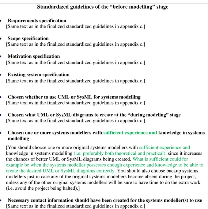
The case study was performed by using the three-step method (i.e. create guidelines – test guidelines – improve guidelines) described in the method section. This three-step method was used when creating standardized guidelines for each respective before, during, and after modelling stage. It took approximately 2 weeks each to create the respective modelling stage’s standardized guidelines. When interviewing personnel at Volvo Construction equipment, the interview questions in appendix b were used. However, only the company supervisor who has 11 years of experience in modelling both financial and automotive industry systems was interviewed. This was due to time constraints etcetera, but at least a well-experienced person in modelling got to review the suggested standardized guidelines. Here follows the process of how the before modelling stage’s standardized guidelines were created. Firstly, relevant information about for example enterprise architecture and modelling technologies was read and gathered from books or academic journals, which resulted in a first draft containing standardized guidelines (step 1.1). Then the company supervisor was
interviewed who thought that the first draft looked good and had no objections (step 1.2). Because of this no further reading or gathering of relevant information was necessary to give more motivations (step 1.3). Secondly, the created standardized guidelines were tested on the Operator ID project (step 2). Here, a person with very little experience in modelling got to try to model a sequence diagram which resulted in it being incorrectly made (e.g. misuse of message-arrows). For this reason, the guideline “chosen one or more systems modellers with sufficient experience and knowledge in systems modelling” had to be updated. Furthermore, we discovered that it takes some time to learn how to use software applications for modelling as well, and therefore the guideline “ensure that the systems modeller(s) knows how to use the chosen software application(s) for systems modelling” was added. Thirdly, the knowledge learnt from step 2 was used to improve the standardized guidelines (step 3) as shown in table 1 (i.e. the green text shows what have been updated or added).
Standardized guidelines of the “before modelling” stage Requirements specification
[Same text as in the finalized standardized guidelines in appendix c.] Scope specification
[Same text as in the finalized standardized guidelines in appendix c.]
Motivation specification
[Same text as in the finalized standardized guidelines in appendix c.]
Existing system specification
[Same text as in the finalized standardized guidelines in appendix c.]
Chosen whether to use UML or SysML for systems modelling
[Same text as in the finalized standardized guidelines in appendix c.]
Chosen what UML or SysML diagrams to create at the “during modeling” stage
[Same text as in the finalized standardized guidelines in appendix c.]
Chosen one or more systems modellers with sufficient experience and knowledge in systems modelling
[You should choose one or more original systems modellers with sufficient experience and knowledge in systems modelling (i.e. preferably both theoretical and practical), since it increases the chances of better UML or SysML diagrams being created. What is sufficient could for example be when the systems modeller possesses enough experience and knowledge to be able to create the desired UML or SysML diagrams correctly. You should also choose backup systems modellers just in case any of the original systems modellers become absent during the project, unless any of the other original systems modellers will be sure to have time to do the extra work (i.e. avoid the project being halted).]
Necessary contact information should have been created for the systems modeller(s) to use
[Same text as in the finalized standardized guidelines in appendix c.]
Chosen what software application(s) to use for systems modelling
[Same text as in the finalized standardized guidelines in appendix c.]
Ensure that the systems modeller(s) knows how to use the chosen software application(s) for systems modelling
[If necessary you should schedule some time for the original systems modellers to learn how to use the chosen software applications before moving onto the “during modelling” stage (i.e. enough to be able to produce the necessary system diagrams). This is because the systems modellers then can focus on creating the system diagrams instead of trying to learn how to use the software applications as well. Here you can also choose to schedule some time for the backup systems modellers to learn how to use the software applications. If you do not schedule some time for the backup systems modellers at this point, then you might have to schedule it later when an original systems modeller becomes absent.]
Here follows the process of how the during modelling stage’s standardized guidelines were created. Firstly, relevant information about for example enterprise architecture and modelling technologies was read and gathered from books or academic journals, which resulted in a first draft containing standardized guidelines (step 1.1). Then the company supervisor was
interviewed who thought the first draft looked good and had no objections (step 1.2). Because of this no further reading or gathering of relevant information was necessary to give more motivations (step 1.3). Secondly, the created standardized guidelines were tested on the Operator ID project (step 2). Here, we discovered that the system requirements kept changing and that it was hard to make changes to the system diagrams all the time, and therefore the guideline “what to think of when modelling UML or SysML diagrams” was updated. Furthermore, we could not fully test the two guidelines “model the UML or SysML diagrams” and “do a final checkup to see if the UML or SysML diagrams are finished”, because the case study ended before the actual system had been developed, tested and become operational. However, one could argue that modelling will be performed during several activities throughout the project [8], and that a final check-up is necessary. Thirdly, the knowledge learnt from step 2 was used to improve the standardized guidelines (step 3) as shown in table 2 (i.e. the green text shows what have been updated, and the red text shows what could not be fully tested).
Standardized guidelines of the “during modelling” stage
Use the available contact information from the “before modelling” stage to get answers to any questions
[Same text as in the finalized standardized guidelines in appendix c.]
The systems modeller(s) should have continuous meetings with relevant personnel or other people
[Same text as in the finalized standardized guidelines in appendix c.]
Be prepared to replace the original systems modeller(s)
[Same text as in the finalized standardized guidelines in appendix c.]
Model the UML or SysML diagrams
[You should start with modelling the system diagrams that were chosen in the “before modelling” stage (i.e. the foundation). However, be prepared to update the created system diagrams, and to model more or fewer diagram types if necessary later on (e.g. if it has been discussed on the continuous meetings with relevant personnel or other people). Note that the modelling of diagrams can take place during all the activities: software specification/system procurement (e.g. to capture the stakeholders’ requirements), software development/software validation/system development (e.g. the system developers might come up with new requirements to capture while
developing or testing the actual system), software evolution/system operation (e.g. the end-users using the operational system might come up with new requirements to capture).]
What to think of when modelling the UML or SysML diagrams
[Here follows two suggestions of what you can do when modelling the UML or SysML diagrams:
(1) If you cannot be certain that no major changes will be made to the system requirements, then
you could use software applications (i.e. not necessarily the ones chosen in the “before modelling” stage) that allows you to more easily create and make changes to system diagrams. Another alternative is also to draw the system diagrams on a whiteboard or piece
of paper and then take pictures of them. Then when you can be certain that no more major changes will be made to the system requirements, you can move onto using more advanced software applications that perhaps offer better functionality (e.g. the ones chosen in the “before modelling” stage). Otherwise it can become quite cumbersome to repeatedly make changes to system diagrams in more advanced and difficult-to-use software applications.
(2) Store and share the created UML or SysML diagrams in a common data repository which the
involved people can access and work through (e.g. systems modellers can make changes to other systems modellers’ system diagrams, or system customers can view the latest versions of the system diagrams).]
Do a final checkup to see if the UML or SysML diagrams are finished
[You need to do a final checkup to ensure that the UML or SysML diagrams are finished (i.e. meet the stakeholders’ requirements). This can be done when for example the new system has been fully tested (i.e. everything works as it should) and is sent to the system customer, or when the system has been operational for a while (e.g. 1-2 months) and the system customers or end-users have not discovered any more faults or new requirements through using it. After this the “during modelling” stage is complete, and later updates to the system diagrams can be considered as further work or system maintenance.]
Table 2 – Changes and tests made to the initial standardized guidelines of the during modelling stage.
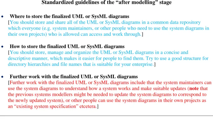
Here follows the process of how the after modelling stage’s standardized guidelines were created. Firstly, relevant information about for example enterprise architecture and modelling technologies was read and gathered from books or academic journals, which resulted in a first draft containing standardized guidelines (step 1.1). Then the company supervisor was
interviewed who thought the first draft looked good and had no objections (step 1.2). Because of this no further reading or gathering of relevant information was necessary to give more motivations (step 1.3). Secondly, the created standardized guidelines were tested on the Operator ID project (step 2). Here, we never really reached the after modelling stage since the case study ended before the system had been developed, tested and become operational. However, we did get to slightly try out the two guidelines “where to store the finalized UML or SysML diagrams” and “how to store the finalized UML or SysML diagrams”, by using an own file naming convention (i.e. [project code] [project name] – [document name]) and storing the files in a common data repository. But we did not get to test the guideline “further work with the finalized UML or SysML diagrams” at all, even though what it states is
reasonable [5]. Thirdly, the knowledge learnt from step 2 told us that the standardized
guidelines were “fine for now” and did not need any improvements (step 3) as shown in table 3 (i.e. the blue text shows what could be tested slightly, and the red text shows what could not be tested at all).
Standardized guidelines of the “after modelling” stage
Where to store the finalized UML or SysML diagrams
[You should store and share all of the UML or SysML diagrams in a common data repository which everyone (e.g. system maintainers, or other people who need to use the system diagrams in their own projects) who is allowed can access and work through.]
How to store the finalized UML or SysML diagrams
[You should store, manage and organize the UML or SysML diagrams in a concise and
descriptive manner, which makes it easier for people to find them. Try to use a good structure for directory hierarchies and file names that is suitable for your enterprise.]
Further work with the finalized UML or SysML diagrams
[Further work with the finalized UML or SysML diagrams include that the system maintainers can use the system diagrams to understand how a system works and make suitable updates (note that the previous systems modellers might be needed to update the system diagrams to correspond to the newly updated system), or other people can use the system diagrams in their own projects as an “existing system specification” etcetera.]
Table 3 – Tests made to the initial standardized guidelines of the after modelling stage.
8.
Results
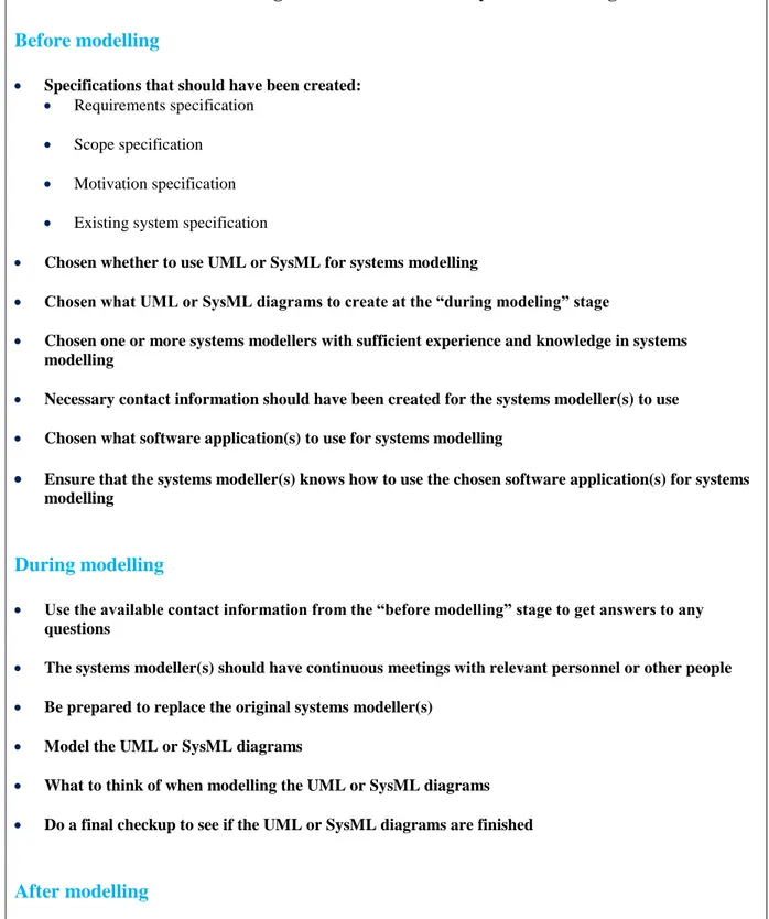
This section presents the different results from the performed research. Regarding the first research question of “how can you create useful standardized guidelines for UML or SysML modelling”, it was proven that the described three-step method (i.e. create guidelines – test guidelines – improve guidelines) in the case study can be used to create useful standardized guidelines. This was confirmed since the three-step method actually produced standardized guidelines that were useful during the real-life Operator ID project. Furthermore, the second research question of “what do useful standardized guidelines for UML or SysML modelling look like”, is answered and visualized through the detailed created standardized guidelines in appendix c. However, in table 4 below you can view a more “lightweight-variant” of the detailed standardized guidelines. The created standardized guidelines consist of a before modelling, during modelling and after modelling stage. These standardized guidelines can help you understand for example what specifications that are needed before modelling, what knowledge the chosen systems modellers should possess, what UML or SysML diagrams to create, where to store the created system diagrams, how to store the created system diagrams, and how to use the created system diagrams in further work. As mentioned before, these standardized guidelines were also useful in the actual work process of the Operator ID project, which strengthens the validity of their usefulness.
Standardized guidelines for UML or SysML modelling Before modelling
Specifications that should have been created:
Requirements specification Scope specification Motivation specification Existing system specification
Chosen whether to use UML or SysML for systems modelling
Chosen what UML or SysML diagrams to create at the “during modeling” stage
Chosen one or more systems modellers with sufficient experience and knowledge in systems
modelling
Necessary contact information should have been created for the systems modeller(s) to use
Chosen what software application(s) to use for systems modelling
Ensure that the systems modeller(s) knows how to use the chosen software application(s) for systems
modelling
During modelling
Use the available contact information from the “before modelling” stage to get answers to any
questions
The systems modeller(s) should have continuous meetings with relevant personnel or other people
Be prepared to replace the original systems modeller(s)
Model the UML or SysML diagrams
What to think of when modelling the UML or SysML diagrams
Do a final checkup to see if the UML or SysML diagrams are finished
After modelling
Where to store the finalized UML or SysML diagrams
How to store the finalized UML or SysML diagrams
Further work with the finalized UML or SysML diagrams
9. Analysis and Discussion
The goal of this thesis work was to answer the two research questions: “how can you create useful standardized guidelines for UML or SysML modelling?” and “what do useful
standardized guidelines for UML or SysML modelling look like?”, which was achieved from the performed research. Firstly, by answering the research question of “how can you create useful standardized guidelines for UML or SysML modelling”, the answer can assist the targeted companies (i.e. in the automotive industry domain) when they are creating their own standardized guidelines. What makes the three-step method work when creating useful standardized guidelines is probably the following: In the first step (i.e. create guidelines) you get a solid mixture of literary and scientific knowledge together with knowledge of the company’s personnel, to base your first draft on. In the second step (i.e. test guidelines) you get to try out the first version in a real-life scenario, which shows you what really works in practice. In the third step (i.e. improve guidelines) you get to improve or finalize the first version with the knowledge learnt from the second step, which can make the standardized guidelines even more useful in reality. Secondly, by answering the research question of “what do useful standardized guidelines for UML or SysML modelling look like”, the answer can give the targeted companies a general idea of what standardized guidelines could look like. Furthermore, the created standardized guidelines can hopefully be used by the targeted companies right away to improve the efficiency of their modelling work, or possibly serve as a foundation when creating their final guidelines later on.
However, there are a few limitations with the performed research. Firstly, the created standardized guidelines are only specialized for companies in the automotive industry
domain. Secondly, the case study has only been made on Volvo Construction Equipment, and just because the created standardized guidelines work for them it does not necessarily mean that they will automatically work for any other company in the automotive industry domain. Thirdly, the case study has only been made on a specific project at Volvo Construction Equipment, and just because the created standardized guidelines work for this particular project it does not ensure that they work for other projects as well. Fourthly, the case study ended before the Operator ID system was developed, tested and became operational which made it impossible to fully test all of created standardized guidelines (e.g. “do a final checkup to see if the UML or SysML diagrams are finished” and “further work with the finalized UML or SysML diagrams”). Fifthly, there might be more preferred ways of creating standardized guidelines than using the described three-step method, which requires further research. Sixthly, only the company supervisor was interviewed and got to properly review the suggested standardized guidelines, but at least they were later on tested in reality. Now, let us analyse the motivations for having each separate guideline in the created standardized guidelines. Firstly, we have the guidelines in the before modelling stage: The
requirements specification is necessary for knowing what the system should be able to do in
order to satisfy the stakeholders’ different needs [5]. Here, the standardized guidelines’ example-table of how to list the stakeholders’ different requirements is inspired from
Sommervilles book [5]. The scope specification is necessary for knowing what is and is not included in the project [6]. The motivation specification is necessary for motivating why an enterprise should go through with a project or investment [7], and hopefully motivating enough to increase the project members’ work performance (e.g. making the systems modellers produce better UML or SysML diagrams) [11], [12]. The existing system
specification is necessary for knowing what constraints or requirements existing systems put
on the new system being created (i.e. if the new system will be integrated with an already existing system), and to make them function efficiently together [5]. Through the existing
system specification, you can analyse how the new system impacts the existing systems as well. An existing system specification can also be valuable if you find inspiration from an attainable existing system when creating the new system (e.g. if the new system will use identical functionalities as of the existing system). Plösch et al.s’ [13] survey results show that software documentation is commonly written or adapted throughout the requirements
engineering, architecture and design, and implementation activity; thus it is stated that the requirements, scope, motivation, and existing system specifications in the standardized guidelines may change later on. The survey results also show that some quality attributes (i.e. accuracy, clarity, consistency, readability, structuredness and understandability) are usually considered very important for software documentation; therefore the requirements, scope, motivation, and existing system specifications should preferably have these quality attributes. Lastly, the survey results show that software documentation quality is quite important for producing good software products, and that it can have a positive influence on a software product’s maintainability, compatibility, functional suitability, portability, reliability and usability; thus the quality of the requirements, scope, motivation, and existing system specifications can impact how good your end-product becomes.
Chosen whether to use UML or SysML for systems modelling is good since the systems
modellers then know what diagrams that are available to use. A recommendation could be to use SysML instead of UML for modelling embedded systems, since it provides the possibility to model software, hardware etcetera [10]. Another recommendation could also be to use UML when you are only concerned with software [3].
Chosen what UML or SysML diagrams to create at the “during modelling” stage gives
the systems modellers something to aim for even though they might have to create more diagrams later on, since another diagram type could be needed to capture newly added
requirements from the stakeholders [5]. A recommendation could be to start out with the class diagram (i.e. modified to block definition diagram in SysML), use case diagram, sequence diagram, and statechart diagram to visualize the essentials of a system [15]. During the case study, it was also discovered that the activity diagram was easily understood by Volvo Construction Equipment’s business personnel and could therefore be good to use as well.
Chosen one or more systems modellers with sufficient experience and knowledge in systems modelling is good since the more experience and knowledge the systems modeller
possesses, the higher are the chances of useful and correct UML or SysML diagrams being produced [9]. During the case study, a person with very little experience in modelling tried to create a sequence diagram which resulted in it being incorrectly made (e.g. misuse of
message-arrows). This comes to show the importance of possessing sufficient experience and knowledge. The systems modeller could for example have taken a course in systems
modelling and then done practical exercises involving systems modelling (i.e. because it is different to do something practically compared to only in theory). If the enterprise has a separate “business side” and “technology side”, then you could split up the modelling workload in the following way: Systems modellers with experience of the “business side” could do the less technical diagrams (e.g. use case diagram or activity diagram), and systems modellers with experience of the “technology side” could do the more technical diagrams (e.g. class/block definition diagram). Furthermore, it is always good to have a backup systems modeller that can do the work in case the original systems modeller becomes absent.
Necessary contact information should have been created for the systems modeller(s) to use is good to have established since the systems modellers will most likely have questions
throughout the project’s work progress. Then it is good to know who to contact with certain questions, and what people to book a meeting with for discussing questions or something else.
Chosen what software application(s) to use for systems modelling is good to have
established from the start to make sure that it is easy for systems modellers to exchange system diagrams with each other. Preferably one single software application should have been chosen, since it then will be easier to make changes to other peoples’ files directly on your own computer (i.e. just import the file into the software application). Another alternative is to have chosen multiple software applications that can import respective software application’s file format. Otherwise you might have to redo the complete system diagram in your own specific software application, if there is no conversion compatibility between the two software applications. In the case study, the two software applications called Sparx Enterprise
Architect and Microsoft Visio were used for systems modelling. Here, it was discovered that you could easily import Microsoft Visio files into Sparx Enterprise Architect, but not the other way around. Also, when importing Microsoft Visio files into Sparx Enterprise Architect there are no guarantees that the contents will remain the same (e.g. symbols can disappear from the system diagrams). To eliminate this problem, a recommendation is simply for all system modellers to use the same software application.
Ensure that the systems modeller(s) knows how to use the chosen software application(s) for systems modelling is good since the systems modellers then know how to properly use
the software application, before entering the “during modelling” stage. This way, the systems modellers can focus on producing system diagrams instead of learning how to use the
software application. During the case study, we had to spend some hours on learning how to use Sparx Enterprise Architect and Microsoft Visio before being able to create the necessary system diagrams. This comes to show that if you do not spend this learning time in the “before modelling” stage, then you must do it in the “during modelling” stage which can delay the production of system diagrams. Whether you should learn how to use the software applications in the “before modelling” or “during modelling” stage is a personal preference, but in the created standardized guidelines it has been placed in the “before modelling” stage to not interfere or delay the production of system diagrams. A convenient way of learning how to use new software applications is by watching video tutorials, which was mainly done in the case study when learning how to use Sparx Enterprise Architect and Microsoft Visio. A suggestion could be to use something similar to Pongnumkul et al.s’ [16] own system called Pause-and-Play, which makes watching video tutorials much more convenient.
Secondly, we have the guidelines in the during modelling stage: Use the available contact
information from the “before modelling” stage to get answers to any questions is good
for the systems modeller to have for getting answers to any of the questions that might arise throughout the project. Furthermore, it enables the possibility to book a meeting with certain contact persons to discuss complex questions.
The systems modeller(s) should have continuous meetings with relevant personnel or other people is good for systems modellers to talk about how the project is going (e.g. if
changes have been made to certain specifications, if more system diagrams are needed to be modelled, if any new questions have come up). This is a great way to for example discover or discuss changes early on and adapt your work. Sommerville [5] repeatedly mentions that it is inevitable for system requirements to change during the software processes. Changes to the system requirements can be made because the stakeholders have gotten a better understanding of what they want the system to be able to do, newly established political laws or rules affect what the system is allowed to do etcetera. Sommerville has even dedicated a whole sub-chapter [5, pp. 111-114] in his book to talk about something called requirements